Unofficial - F5 Certification Exam Prep Material > F5 101 - App Delivery Fundamentals Exam Study Guide - Created 03/06/20 Source | Edit on
Section 4 – Knowledge
Objective - 4.01 Explain common uses for ICMP
4.01 - Explain the purpose of an IP TTL
https://en.wikipedia.org/wiki/Time_to_live
IP TTL
Under the Internet Protocol, TTL is an 8-bit field. In the IPv4 header, TTL is the 9th octet of 20. In the IPv6 header, it is the 8th octet of 40. The maximum TTL value is 255, the maximum value of a single octet. A recommended initial value is 64.
The time-to-live value can be thought of as an upper bound on the time that an IP datagram can exist in an Internet system. The TTL field is set by the sender of the datagram and reduced by every router on the route to its destination. If the TTL field reaches zero before the datagram arrives at its destination, then the datagram is discarded and an Internet Control Message Protocol (ICMP) error datagram (11 - Time Exceeded) is sent back to the sender. The purpose of the TTL field is to avoid a situation in which an undeliverable datagram keeps circulating on an Internet system, and such a system eventually becoming swamped by such “immortals”.
In theory, under IPv4, time to live is measured in seconds, although every host that passes the datagram must reduce the TTL by at least one unit. In practice, the TTL field is reduced by one on every hop. To reflect this practice, the field is renamed hop limit in IPv6.
4.01 - Explain the purpose of ICMP echo request/reply
https://en.wikipedia.org/wiki/Ping_(networking_utility)
ICMP - Ping
Ping is a computer network administration software utility used to test the reachability of a host on an Internet Protocol (IP) network. It is available for virtually all operating systems that have networking capability, including most embedded network administration software.
Ping measures the round-trip time for messages sent from the originating host to a destination computer that are echoed back to the source. The name comes from active sonar terminology that sends a pulse of sound and listens for the echo to detect objects under water.
Ping operates by sending Internet Control Message Protocol (ICMP) echo request packets to the target host and waiting for an ICMP echo reply. The program reports errors, packet loss, and a statistical summary of the results, typically including the minimum, maximum, the mean round-trip times, and standard deviation of the mean.
4.01 - Explain reasons for ICMP unreachable
https://en.wikipedia.org/wiki/Internet_Control_Message_Protocol
ICMP Destination unreachable
Destination unreachable is generated by the host or its inbound gateway to inform the client that the destination is unreachable for some reason. Reasons for this message may include: the physical connection to the host does not exist (distance is infinite); the indicated protocol or port is not active; the data must be fragmented but the ‘don’t fragment’ flag is on. Unreachable TCP ports notably respond with TCP RST rather than a destination unreachable type 3 as might be expected. Destination unreachable is never reported for IP Multicast transmissions.
Objective - 4.02 Map functionality to OSI model
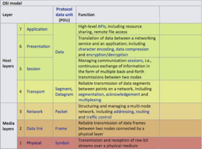
4.02 - Map functionality to OSI model
https://en.wikipedia.org/wiki/OSI_model
https://www.youtube.com/watch?v=i9RL5jD9cTI
OSI Model
The Open Systems Interconnection model (OSI model) is a conceptual model that characterizes and standardizes the communication functions of a telecommunication or computing system without regard to its underlying internal structure and technology. Its goal is the interoperability of diverse communication systems with standard communication protocols. The model partitions a communication system into abstraction layers. The original version of the model had seven layers.
A layer serves the layer above it and is served by the layer below it. For example, a layer that provides error-free communications across a network provides the path needed by applications above it, while it calls the next lower layer to send and receive packets that constitute the contents of that path. Two instances at the same layer are visualized as connected by a horizontal connection in that layer.
The model is a product of the Open Systems Interconnection project at the International Organization for Standardization (ISO).
4.02 - Identify the layer for a MAC address
https://en.wikipedia.org/wiki/OSI_model
Layer 2: Data Link Layer
The data link layer provides node-to-node data transfer. A link between two directly connected nodes. It detects and possibly corrects errors that may occur in the physical layer. It defines the protocol to establish and terminate a connection between two physically connected devices. It also defines the protocol for flow control between them.
IEEE 802 divides the data link layer into two sublayers:
Medium access control (MAC) layer – responsible for controlling how devices in a network gain access to a medium and permission to transmit data.
Logical link control (LLC) layer – responsible for identifying and encapsulating network layer protocols, and controls error checking and frame synchronization.
The MAC and LLC layers of IEEE 802 networks such as 802.3 Ethernet, 802.11 Wi-Fi, and 802.15.4 ZigBee operate at the data link layer.
4.02 - Identify the layer for a UDP/TCP port
https://en.wikipedia.org/wiki/OSI_model
Layer 4: Transport Layer
The transport layer provides the functional and procedural means of transferring variable-length data sequences from a source to a destination host, while maintaining the quality of service functions.
The transport layer controls the reliability of a given link through flow control, segmentation/desegmentation, and error control. Some protocols are state- and connection-oriented. This means that the transport layer can keep track of the segments and re-transmit those that fail delivery. The transport layer also provides the acknowledgement of the successful data transmission and sends the next data if no errors occurred. The transport layer creates segments out of the message received from the application layer. Segmentation is the process of dividing a long message into smaller messages.
An easy way to visualize the transport layer is to compare it with a post office, which deals with the dispatch and classification of mail and parcels sent. A post office inspects only the outer envelope of mail to determine its delivery. Higher layers may have the equivalent of double envelopes, such as cryptographic presentation services that can be read by the addressee only. Roughly speaking, tunneling protocols operate at the transport layer, such as carrying non-IP protocols such as IBM’s SNA or Novell’s IPX over an IP network, or end-to-end encryption with IPsec. While Generic Routing Encapsulation (GRE) might seem to be a network-layer protocol, if the encapsulation of the payload takes place only at the endpoint, GRE becomes closer to a transport protocol that uses IP headers but contains complete Layer 2 frames or Layer 3 packets to deliver to the endpoint. L2TP carries PPP frames inside transport segments.
Although not developed under the OSI Reference Model and not strictly conforming to the OSI definition of the transport layer, the Transmission Control Protocol (TCP) and the User Datagram Protocol (UDP) of the Internet Protocol Suite are commonly categorized as layer-4 protocols within OSI.
4.02 - Identify the layer for an IP address
https://en.wikipedia.org/wiki/OSI_model
Layer 3: Network Layer
The network layer provides the functional and procedural means of transferring variable length data sequences (called packets) from one node to another connected in “different networks”. A network is a medium to which many nodes can be connected, on which every node has an address and which permits nodes connected to it to transfer messages to other nodes connected to it by merely providing the content of a message and the address of the destination node and letting the network find the way to deliver the message to the destination node, possibly routing it through intermediate nodes. If the message is too large to be transmitted from one node to another on the data link layer between those nodes, the network may implement message delivery by splitting the message into several fragments at one node, sending the fragments independently, and reassembling the fragments at another node. It may, but does not need to, report delivery errors.
Message delivery at the network layer is not necessarily guaranteed to be reliable; a network layer protocol may provide reliable message delivery, but it need not do so.
A number of layer-management protocols, a function defined in the management annex, ISO 7498/4, belong to the network layer. These include routing protocols, multicast group management, network-layer information and error, and network-layer address assignment. It is the function of the payload that makes these belong to the network layer, not the protocol that carries them.
4.02 - Identify the layer for applications
https://en.wikipedia.org/wiki/OSI_model
Layer 7: Application Layer
The application layer is the OSI layer closest to the end user, which means both the OSI application layer and the user interact directly with the software application. This layer interacts with software applications that implement a communicating component. Such application programs fall outside the scope of the OSI model. Application-layer functions typically include identifying communication partners, determining resource availability, and synchronizing communication. When identifying communication partners, the application layer determines the identity and availability of communication partners for an application with data to transmit. The most important distinction in the application layer is the distinction between the application-entity and the application. For example, a reservation website might have two application-entities: one using HTTP to communicate with its users, and one for a remote database protocol to record reservations. Neither of these protocols have anything to do with reservations. That logic is in the application itself. The application layer has no means to determine the availability of resources in the network.
Objective - 4.03 Explain use of TLS/SSL
4.03 - Explain use of TLS/SSL
https://en.wikipedia.org/wiki/Transport_Layer_Security
Transport Layer Security
Transport Layer Security (TLS), and its now-deprecated predecessor, Secure Sockets Layer (SSL), are cryptographic protocols designed to provide communications security over a computer network. Several versions of the protocols find widespread use in applications such as web browsing, email, instant messaging, and voice over IP (VoIP). Websites can use TLS to secure all communications between their servers and web browsers.
Client-server applications use the TLS protocol to communicate across a network in a way designed to prevent eavesdropping and tampering.
Since applications can communicate either with or without TLS (or SSL), it is necessary for the client to indicate to the server the setup of a TLS connection. One of the main ways of achieving this is to use a different port number for TLS connections, for example port 443 for HTTPS. Another mechanism is for the client to make a protocol-specific request to the server to switch the connection to TLS; for example, by making a STARTTLS request when using the mail and news protocols.
Once the client and server have agreed to use TLS, they negotiate a stateful connection by using a handshaking procedure. The protocols use a handshake with an asymmetric cipher to establish not only cipher settings but also a session-specific shared key with which further communication is encrypted using a symmetric cipher. During this handshake, the client and server agree on various parameters used to establish the connection’s security
4.03 - Explain the purpose of TLS/SSL certificates (self-signed vs CA signed)
https://en.wikipedia.org/wiki/Certificate_authority
Digital Certificates
A digital certificate certifies the ownership of a public key by the named subject of the certificate and indicates certain expected usages of that key. This allows others (relying parties) to rely upon signatures or on assertions made by the private key that corresponds to the certified public key.
Certificate Authorities
TLS typically relies on a set of trusted third-party certificate authorities to establish the authenticity of certificates. Trust is usually anchored in a list of certificates distributed with user agent software and can be modified by the relying party.
Trusted certificates can be used to create secure connections to a server via the Internet. A certificate is essential in order to circumvent a malicious party which happens to be on the route to a target server which acts as if it were the target. Such a scenario is commonly referred to as a man-in-the-middle attack. The client uses the CA certificate to authenticate the CA signature on the server certificate, as part of the authorizations before launching a secure connection. Usually, client software—for example, browsers—include a set of trusted CA certificates. This makes sense, as many users need to trust their client software. A malicious or compromised client can skip any security check and still fool its users into believing otherwise. Mozilla, which is a non-profit business, issues several commercial CA certificates with its products. While Mozilla developed their own policy, the CA/Browser Forum developed similar guidelines for CA trust. A single CA certificate may be shared among multiple CAs or their resellers. A root CA certificate may be the base to issue multiple intermediate CA certificates with varying validation requirements.
In addition to commercial CAs, some non-profits issue digital certificates to the public without charge; notable examples are CAcert and Let’s Encrypt. Large organizations or government bodies may have their own PKIs (public key infrastructure), each containing their own CAs.
Any site using self-signed certificates acts as its own CA. These self-signed certificates will not be known publicly and thus not a part of the default trusted CA certificates.
4.03 - Explain the rationale for using TLS/SSL
https://en.wikipedia.org/wiki/Transport_Layer_Security
Rationale
When secured by TLS, connections between a client (e.g., a web browser) and a server (e.g., wikipedia.org) should have one or more of the following properties:
- The connection is private (or secure) because symmetric cryptography is used to encrypt the data transmitted. The keys for this symmetric encryption are generated uniquely for each connection and are based on a shared secret that was negotiated at the start of the session. The server and client negotiate the details of which encryption algorithm and cryptographic keys to use before the first byte of data is transmitted. The negotiation of a shared secret is both secure (the negotiated secret is unavailable to eavesdroppers and cannot be obtained, even by an attacker who places themselves in the middle of the connection) and reliable (no attacker can modify the communications during the negotiation without being detected).
- The identity of the communicating parties can be authenticated using public-key cryptography. This authentication can be made optional but is generally required for at least one of the parties (typically the server).
- The connection is reliable because each message transmitted includes a message integrity check using a message authentication code to prevent undetected loss or alteration of the data during transmission.
In addition to the properties above, careful configuration of TLS can provide additional privacy-related properties such as forward secrecy, ensuring that any future disclosure of encryption keys cannot be used to decrypt any TLS communications recorded in the past.
Objective - 4.04 Explain the function of a VPN
4.04 - Explain the function of a VPN
https://en.wikipedia.org/wiki/Virtual_private_network
VPN
A virtual private network (VPN) extends a private network across a public network and enables users to send and receive data across shared or public networks as if their computing devices were directly connected to the private network. Applications running on a computing device, e.g., a laptop, desktop, smartphone, across a VPN may therefore benefit from the functionality, security, and management of the private network. Encryption is a common, though not an inherent, part of a VPN connection.
4.04 - Explain the rationale for using VPN (privacy, encryption, anonymity)
Rationale for VPN
VPN technology was developed to allow remote users and branch offices to access corporate applications and resources. To ensure security, the private network connection is established using an encrypted layered tunneling protocol, and VPN users use authentication methods, including passwords or certificates, to gain access to the VPN. In other applications, Internet users may secure their connections with a VPN to circumvent geo-restrictions and censorship or to connect to proxy servers to protect personal identity and location to stay anonymous on the Internet.
4.04 - Identify valid uses for VPN
https://www.f5.com/services/resources/glossary/ssl-vpn
Uses for VPN
VPNs can help increase the security of transmitted data. There are multiple types of VPNs and the most common business uses for VPN are for individual remote access, site-to-site tunnels. SSL VPNs are used for Individual remote access because the client software is a common browser. This makes use and support easy. An IPsec VPN uses the standard IPsec mechanism to establish a VPN over the public Internet. An IPsec VPN is most useful for establishing a VPN between fixed end-points, such as two offices for a site-to-site tunnel.
Objective - 4.05 Explain high availability (HA) concepts
4.05 - Explain methods of providing HA integrity
Levels of HA Integrity
HA integrity can be improved through providing deeper system monitoring or deeper levels of availability monitoring of the resources. At the highest levels, if an entire DC is offline you can do checks at a global level and take action to send traffic to a second DC with a GSLB device. Within a DC Basic HA can be achieved between two systems by simple health checks to see if the active system is up and operating. Or you may have a cluster of systems each backing up others in the cluster in an N+1 style configuration, such as device service clustering (DSC) which is covered in the next section. Further checking of resources can also be provided by BIG-IP through HA Groups enabled in a DSC.
Introduction to failover
When you configure a Sync-Failover device group as part of device service clustering, you ensure that a user-defined set of application-specific IP addresses, known as a floating traffic group, can fail over to another device in that device group if necessary. DSC failover gives you granular control of the specific configuration objects that you want to include in failover operations.
If you want to exclude certain devices on the network from participating in failover operations, you simply exclude them from membership in that particular Sync-Failover device group.
What triggers failover?
The BIG-IP system initiates failover of a traffic group according to any of several events that you define. These events fall into these categories:
System fail-safe
With system fail-safe, the BIG-IP system monitors various hardware components, as well as the heartbeat of various system services. You can configure the system to initiate failover whenever it detects a heartbeat failure.
Gateway fail-safe
With gateway fail-safe, the BIG-IP system monitors traffic between an active BIG-IP® system in a device group and a pool containing a gateway router. You can configure the system to initiate failover whenever some number of gateway routers in a pool of routers becomes unreachable.
VLAN fail-safe
With VLAN fail-safe, the BIG-IP system monitors network traffic going through a specified VLAN. You can configure the system to initiate failover whenever the system detects a loss of traffic on the VLAN and the fail-safe timeout period has elapsed.
HA groups
With an HA group, the BIG-IP system monitors the availability of resources for a specific traffic group. Examples of resources are trunk links, pool members, and VIPRION® cluster members. If resource levels fall below a user-defined level, the system triggers failover.
Auto-failback
When you enable auto-failback, a traffic group that has failed over to another device fails back to a preferred device when that device is available. If you do not enable auto-failback for a traffic group, and the traffic group fails over to another device, the traffic group remains active on that device until that device becomes unavailable.
About IP addresses for failover
Part of configuring a Sync-Failover device group is configuring failover. Configuring failover requires you to specify certain types of IP addresses on each device. Some of these IP addresses enable continual, high availability (HA) communication among devices in the device group, while other addresses ensure that application traffic processing continues when failover occurs.
The IP addresses that you need to specify as part of HA configuration are:
A local, static self IP address for VLAN HA
This unicast self IP address is the main address that other devices in the device group use to communicate continually with the local device to assess the health of that device. When a device in the device group fails to receive a response from the local device, the BIG-IP system triggers failover.
A local management IP address
This unicast management IP address serves the same purpose as the static self IP address for VLAN HA, but is only used when the local device is unreachable through the HA static self IP address.
One or more floating IP addresses associated with a traffic group
These are the IP addresses that application traffic uses when passing through a BIG-IP system. Each traffic group on a device includes application-specific floating IP addresses as its members. Typical traffic group members are: floating self IP addresses, virtual addresses, NAT or SNAT translation addresses, and IP addresses associated with an iApp application service. When a device with active traffic groups becomes unavailable, the active traffic groups become active on other device in the device group. This ensures that application traffic processing continues with little to no interruption.
4.05 - Explain methods of providing HA
Providing HA
An active-standby pair is a pair of BIG-IP devices configured so that one device is actively processing traffic while the other device remains ready to take over if failover occurs. The two devices synchronize their configuration data and can fail over to one another in the event that one of the devices becomes unavailable.
An active-active pair is a pair of BIG-IP devices configured so that both devices are actively processing traffic and are ready to take over one another if failover occurs. The two devices synchronize their configuration data to one another.
Device service clustering
Device service clustering, or DSC, is an underlying architecture within BIG-IP Traffic Management Operation System (TMOS). DSC provides synchronization and failover of BIG-IP configuration data at user-defined levels of granularity, among multiple BIG-IP devices on a network. More specifically, you can configure a BIG-IP device on a network to:
- Synchronize some or all of its configuration data among several BIG-IP devices
- Fail over to one of many available devices
- Mirror connections to a peer device to prevent interruption in service during failover
If you have two BIG-IP devices only, you can create either an active-standby or an active-active configuration. With more than two devices, you can create a configuration in which multiple devices are active and can fail over to one of many, if necessary.
By setting up DSC, you ensure that BIG-IP configuration objects are synchronized and can fail over at useful levels of granularity to the most-available BIG-IP devices on the network. You also ensure that failover from one device to another, when enabled, occurs seamlessly, with minimal to no interruption in application delivery.
The BIG-IP system supports either homogeneous or heterogeneous hardware platforms within a device group.
4.05 - Explain advantages of HA
https://en.wikipedia.org/wiki/High_availability
Advantages of HA
High availability (HA) is a characteristic of a system, which aims to ensure an agreed level of operational performance, usually uptime, for a higher than normal period. High availability requires less human intervention to restore operation in complex systems; the reason for this being that the most common cause for outages is human error.
Objective - 4.06 Explain reasons for support services (DNS, NTP, syslog, SNMP, etc)
4.06 - Explain the purpose of DNS
https://computer.howstuffworks.com/dns.htm
Domain Name System (DNS)
If you’ve ever used the Internet, it’s a good bet that you’ve used the Domain Name System, or DNS, even without realizing it. DNS is a protocol within the set of standards for how computers exchange data on the Internet and on many private networks, known as the TCP/IP protocol suite. Its basic job is to turn a user-friendly domain name like “howstuffworks.com” into an Internet Protocol (IP) address like 70.42.251.42 that computers use to identify each other on the network. It’s like your computer’s GPS for the Internet.
Computers and other network devices on the Internet use an IP address to route your request to the site you’re trying to reach. This is similar to dialing a phone number to connect to the person you’re trying to call. Thanks to DNS, though, you don’t have to keep your own address book of IP addresses. Instead, you just connect through a domain name server, also called a DNS server or name server, which manages a massive database that maps domain names to IP addresses.
4.06 - Given a list of tools, select the appropriate tool to confirm DNS resolution is successful for a host name
https://blog.dnsimple.com/2015/02/top-dns-lookup-tools/
DNS Tools
Most operating systems come with a standard set of DNS tools that allow you to perform certain tasks.
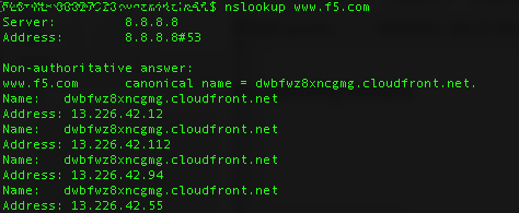
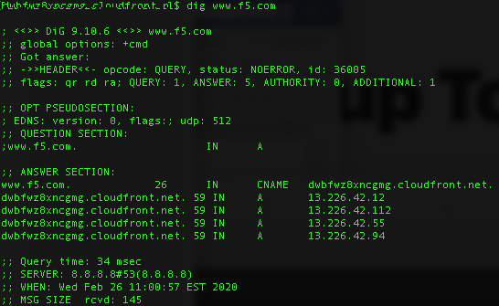
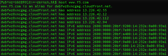
Tools such as “nsLookup”, “dig” and “host” to name a few are useful for analyzing DNS records. These tools allow you to perform manual DNS lookups, through your locally defined DNS server or via alternate servers. You should be familiar with all tools that can be used to check DNS functionality not just these few, as well as the types of output from these tools.
Example of nslookup command output:
Example of dig command output:
Example of host command output:
4.06 - Explain what syslog is
https://en.wikipedia.org/wiki/Syslog
syslog
In computing, syslog is a standard for message logging. It allows separation of the software that generates messages, the system that stores them, and the software that reports and analyzes them. Each message is labeled with a facility code, indicating the software type generating the message, and assigned a severity level.
Computer system designers may use syslog for system management and security auditing as well as general informational, analysis, and debugging messages. A wide variety of devices, such as printers, routers, and message receivers across many platforms use the syslog standard. This permits the consolidation of logging data from different types of systems in a central repository. Implementations of syslog exist for many operating systems.
4.06 - Explain the purpose of NTP
https://en.wikipedia.org/wiki/Network_Time_Protocol
NTP Purpose
The Network Time Protocol (NTP) is a networking protocol for clock synchronization between computer systems over packet-switched, variable-latency data networks. In operation since before 1985, NTP is one of the oldest Internet protocols in current use.
NTP is intended to synchronize all participating computers to within a few milliseconds of Coordinated Universal Time (UTC). It uses the intersection algorithm to select accurate time servers and is designed to mitigate the effects of variable network latency. NTP can usually maintain time to within tens of milliseconds over the public Internet and can achieve better than one millisecond accuracy in local area networks under ideal conditions. Asymmetric routes and network congestion can cause errors of 100 ms or more.
The protocol is usually described in terms of a client-server model but can as easily be used in peer-to-peer relationships where both peers consider the other to be a potential time source.
4.06 - Explain SNMP as it pertains to ADC element monitoring
https://support.f5.com/csp/article/K4026
BIG-IP platforms support SNMP monitoring
You can use Simple Network Management Protocol (SNMP) to query and monitor all BIG-IP platforms for chassis fan speed, chassis temperature, CPU fan speed, CPU temperature, and power supply status.
The system uses an SNMP script, system_check, to gather the required information. The system then monitors this information and, when it detects that certain parameters exceed the system-defined threshold, it notifies you by either logging a message to the system log file or issuing an SNMP trap (when you configure the system to send traps).
You can use SNMP polling to obtain this information by importing the F5 management information base (MIB) file, F5-BIGIP-SYSTEM-MIB.txt, into your SNMP polling device and configuring the BIG-IP SNMP agent to allow access from the polling device.
Conclusion
This document is intended as a study guide for the F5 101 – Application Delivery Fundamentals exam. This study guide is not an all-inclusive document that will guarantee a passing grade on the exam. It is intended to be a living doc and any feedback or material that you feel should be included, to help exam takers better prepare, can be sent to channeleng@f5.com.
Thank you for using this study guide to prepare the 101 – Application Delivery Fundamentals exam and good luck with your certification goals.
Thanks
Eric Mitchell
Sr. Systems Engineer, Covering Indian GSIs