Installation workflow
Deploying BIG‑IP Next for Kubernetes on DPU happens in six phases. Each phase must finish before you start the next one. The workflow shows the full sequence, including the decision point for users who already have a Kubernetes cluster, the steps in each phase, and their dependencies.
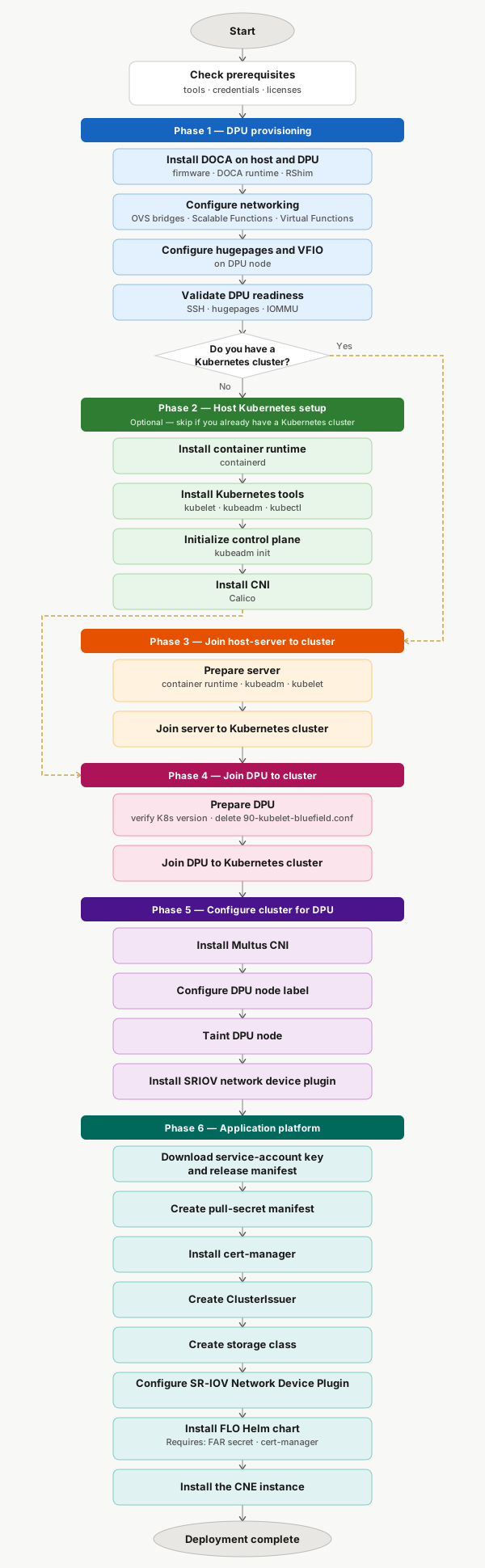
Phase 1 — DPU provisioning
Phase 1 prepares the NVIDIA BlueField‑3 DPU to host the BNK data plane. You install DOCA on the host and DPU, set up the networking layer that connects them (OVS bridges, scalable functions, and virtual functions), and set the kernel parameters that TMM needs (hugepages and VFIO). The phase ends with a readiness check to confirm the DPU is configured correctly.
Run this phase once. Skip it if your DPU is already provisioned.
Phase 2 — Host Kubernetes setup (optional)
Skip this phase if you already have a Kubernetes cluster. If you do not have a cluster, you must set up Kubernetes on the host server before you continue. This includes installing the container runtime and Kubernetes tools, initializing the control plane, and installing a CNI plugin such as Calico. F5 does not provide documentation for this phase. For guidance, see the Kubernetes documentation.
Phase 3 — Join host server to cluster
Phase 3 adds the host server to the Kubernetes cluster. You install the container runtime, kubeadm, and kubelet, then join the server to the cluster.
Phase 4 — Join DPU to cluster
Phase 4 adds the DPU to the Kubernetes cluster as a worker node. You verify the Kubernetes version on the DPU, remove the default kubelet configuration file (90-kubelet-bluefield.conf), and join the DPU with the standard kubeadm join command.
Phase 5 — Configure cluster for DPU
Phase 5 configures the cluster so Kubernetes can schedule workloads on the DPU. You install Multus CNI for multi‑interface support, apply the DPU node label so Kubernetes knows to schedule TMM there, taint the DPU node to block other workloads, and install the SR‑IOV Network Device Plugin.
Phase 6 — Application platform
Phase 6 deploys the F5 software stack on the cluster. Each step creates resources that the next step needs.
Download service-account key and release manifest — Downloads the credentials and release manifest needed to pull F5 images from the F5 Artifact Registry.
Create pull-secret manifest — Creates the manifest that stores the FAR credentials for use across the deployment.
Install cert‑manager — Installs the operator that issues and rotates TLS certificates for F5 components.
Create ClusterIssuer — Configures cert‑manager with the certificate authority to use.
Create storage class — Creates the storage class that persistent components use.
Configure SR‑IOV Network Device Plugin — Configures the plugin so the cluster can expose SR‑IOV virtual functions to pods running on the DPU.
Install FLO Helm chart — Installs the F5 Lifecycle Operator, which manages the BNK component lifecycle. Requires the FAR pull secret and cert‑manager.
Install the CNE instance — Applies the CNEInstance custom resource. This triggers FLO to deploy TMM on the DPU node. The deployment is complete when TMM is running on the DPU.