3.3. Creating an Inline HTTP Service
3.3.1. What it is
An inline HTTP service is defined by the following primary characteristics:
Layer 3: It assigns IP addresses to network interfaces and participates in traffic routing.
Inline: It has physically or logically separate inbound (to-device) and outbound (from-device) interfaces.
HTTP Proxy: It changes the source port as traffic flows through.
A transparent proxy is similar to an inline layer 3 service, except that it proxies traffic and thus minimally changes the source port.
An explicit forward proxy creates a listener IP address and port that traffic must be directed to.
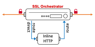
Figure 33: Inline HTTP service
Many modern security products fit into this category, including products by Cisco, Symantec, McAfee and Forcepoint. Inline HTTP devices route traffic, very much like layer 3 devices, and can modify or break (i.e. reset, drop) that traffic in real time. The SSL Orchestrator routes traffic to the service from one VLAN, and the service will typically gateway route the traffic back to the F5 BIG-IP on another VLAN. Inline HTTP devices can also be defined as explicit or transparent forward proxy.
3.3.2. How to build it
Either from a topology workflow or directly under the Services tab in the SSL Orchestrator user interface, click the Add button to create a new inline HTTP service.
Inline HTTP Service |
User Input |
|---|---|
Service Properties |
Choose an inline HTTP service from the catalog or select the “Generic HTTP Service” and click the Add button. |
Name |
Provide a name for this service. |
Description |
Optionally provide a description. |
IP Family |
Choose between IPv4 and IPv6. |
Auto Manage Addresses |
When enabled the Auto Manage setting provides a set of unique, non-overlapping, non-routable IP addresses to be used by the security service. If disabled, the To Service Configuration and From Service Configuration addresses must be defined manually. It is recommended to leave this option enabled (checked). |
Proxy Type |
Select either Transparent or Explicit, as configured on the inline HTTP device. |
To Service Configuration |
This setting defines how traffic flows to the inline service, by which VLAN and IP subnet. The IP address assigned here represents the F5 BIG-IP VLAN self-IP and the to-service side subnet to be used on the layer 3 device.
|
Service Down Action |
Optionally select an alternate service down action. This setting defines what happens if all devices in a service pool are down and will either ignore (skip this service in the chain), reset, or drop the traffic. |
Security Devices |
This setting defines the entry point IP address of the layer 3 service, defined on its “to-service” interface. Multiple IP addresses can be assigned here to load balance multiple layer 3 devices.
Click the Done button to add each device. |
Device Monitor |
Optionally define an alternate monitor. In most cases the default gateway_icmp monitor is preferable for inline layer 3 services. |
From Service Configuration |
This setting defines how traffic flows back to the F5 BIG-IP from the inline service, by which VLAN and IP subnet. The IP address assigned here represents the F5 BIG-IP VLAN self-IP and the from-service side subnet to be used on the layer 3 device. This IP address will also be the gateway IP address on the layer 3 device.
|
Authentication Offload |
Enable this option if the F5 Access Policy Manager (APM) module is licensed, provisioned, and an authentication profile is attached to the topology. This option when enabled will send the authenticated user identity to the inline HTTP service as an X-Authenticated-User HTTP header. |
Manage SNAT Settings |
Optionally enable source address translation across this service. |
iRules |
Optionally insert additional iRule processing. No additional iRules are required. |
Click Save & Next to proceed.
The workflow will proceed to the Service Chains page to allow adding of this new service to a service chain. Once complete here, if in a topology workflow click Save & Next to continue. If adding the service directly, click the Deploy button.
3.3.3. How it works
An inline HTTP service is physically the same as an inline layer 3 service except for the following characteristics:
An HTTP service proxies traffic and will always minimally change the source port. This affects the way SSL Orchestrator tracks packet flows through the service chain and must be managed (signaled) in a different way from inline layer 2 and layer 3 services.
This is the most important distinction between HTTP (proxy) and L3 devices. An L3 device will simply route traffic across its interfaces without manipulating the packet headers. A proxy device, by definition, alters the packets headers. SSL Orchestrator uses the ephemeral packet tuple information to track packets across inline L2 and L3 devices. But as an HTTP proxy device manipulates this information, SSL Orchestrator uses an HTTP header signal across an HTTP proxy device. This signaling mechanism limits an inline HTTP proxy device to unencrypted HTTP traffic.
An HTTP service can either be defined as a transparent forward proxy or an explicit forward proxy. The former is most like an inline layer 3 service, except for source port translation. The latter creates a listening IP address and port interface that SSL Orchestrator sends traffic to (instead of routing through).
Also like an inline layer 3 service, traffic routes through physically or logically separate interfaces. Unlike a layer 2 device, HTTP and layer 3 devices expose IP addresses and participate in routing. And unlike passive TAP devices, are able to affect the traffic in real time. They may, for example, drop/reset a traffic flow, rewrite/scrub content, or generate blocking page actions. The SSL Orchestrator dynamic service chain mechanism freely allows all of these actions to work as expected. If an inline service resets the traffic, that reset action will cascade out to the client and server. If the inline service generates a blocking page, that page will be sent to the client.
Service Properties - the Service Properties page represents a Service Catalog of validated product integrations and represents each of the five security product types. If your security product is not listed, there are also “generic” service icons at the bottom of the catalog.
Proxy Type - this setting defines the service as a transparent or explicit forward proxy. The former routes traffic through the device, while the latter forwards traffic to a listening IP address and port interface on the device.
Auto Manage Addresses - in environments where SSL Orchestrator is introduced to existing security devices, it is a natural tendency to want to leave these devices where they are. While SSL Orchestrator certainly allows this, by not moving the security stack into “protected enclaves”, you run the risk of exposing sensitive decrypted traffic to other devices that may be connected to these existing networks. It is therefore highly recommended, and a security recommended practice, to re-locate and isolate these security products. The SSL Orchestrator service configurations provide this isolation through sets of unique, non-overlapping, non-routable IP addresses. The Auto Manage Addresses option enables and disables this protection feature. When enabled, the service configuration defines the internal RFC2544 addressing that the services will use. When disabled, IP addressing must be defined manually.
To Service Configuration - with the Auto Manage Addresses option enabled, this IP address will be pre-defined, therefore the to-service interface of the service must match this IP subnet. SSL Orchestrator uses an RFC2544 internal, non-routable address space (198.19.x.y/19). With the Auto Manage Addresses option disabled, the IP addresses must be defined manually. This assigned address specifies the F5 BIG-IP VLAN self-IP from which traffic will be flowing to the service.
Service Down Action - a security service defines a pool of one or more load balanced and monitored devices. Depending on the state of the monitor, a different action may be taken. It may be most appropriate, for example, to simply bypass a failed service (i.e. all of the members are down) in order to maintain availability.
Security Devices - an inline HTTP service may be defined as the load balances set of multiple devices on the same IP subnets. Minimally one device IP address must be defined.
When the Proxy Type option is set to Explicit, this setting must specify the listening IP address and port of the HTTP proxy device.
When the Proxy Type option is set to Transparent, this setting must specify the to-service IP address of the HTTP proxy device.
Device Monitor - as stated, the service configuration builds a layer 3 path to an inline layer 3 device. Thus, a typical monitor for this type of device sends a health check directly to the device.
From Service Configuration - with the Auto Manage Addresses option enabled, this IP address will be pre-defined, therefore the from-service interface of the service must match this IP subnet. SSL Orchestrator uses an RFC2544 internal, non-routable address space (198.19.x.y/19). With the Auto Manage Addresses option disabled, the IP addresses must be defined manually. This assigned address specifies the F5 BIG-IP VLAN self-IP to which traffic will be flowing from the service back to the F5 BIG-IP. This IP address should also be the gateway routing address on the layer 3 service to ensure all traffic is sent back to the F5 BIG-IP.
Authentication Offload - security devices attached to the SSL Orchestrator are opaque to the external environment. They are protected, isolated, and do not interact outside of the internal connectivity with the F5 BIG-IP. If an HTTP proxy device requires authenticated user identity, this information cannot come from direct challenge-response authentication with the user. Authentication must, therefore, be performed at the SSL Orchestrator client-facing interface, via Access Policy Manager (APM) integration. To then pass that authenticated user identity information to the inline HTTP device, the Authentication Offload option will automatically send this as an X-Authenticated-User HTTP header (if the value is populated). For most proxy-type security products, modifying the configuration to consume this header in lieu of direct challenge-response authentication is a trivial task.
Manage SNAT Settings - this optional setting enables source address translation across the layer 3 service. It is unusual to enable source address translation however this setting is most useful when a single layer 3 service is shared between non-HA SSL Orchestrator appliances. The setting would apply a unique source IP address from each SSL Orchestrator appliance to aid in policy routing.
iRules - iRule logic can be defined at multiple strategic points within an SSL Orchestrator configuration. An iRule attached at the service level specifically targets traffic flowing across this service. iRules are an extremely powerful tool for manipulation and observation of real time traffic flows. You could, for example, insert an iRule to produce additional logging, insert or remove headers, or to inspect and/or act on some values in the request or response. Keep in mind here that an iRule inserted at a service is interacting with the flow at that service and should not be used to control flow, though it could be used to generate a reset or blocking page. iRules used here are intended to work primarily at the application layer (ex. HTTP).
3.3.4. Routing Considerations
Within the SSL Orchestrator service chain, and in the absence of SNAT, an HTTP security service will consume IP traffic sourced from the true client IP and destined for the true destination IP. The HTTP security service must have a route to pass all unknown traffic (i.e. traffic to the Internet in a forward proxy scenario) to its outbound interface. And unless it possesses some form of layer 2 “return-to-sender” function, it may also require a separate route to send return traffic (to the client’s IP) through its inbound interface. As an example, take the following scenario:
Client IP subnet: 10.1.10.0/24
Service inbound subnet: 198.19.64.0/25 (F5 self-IP is 198.19.64.7)
Service outbound subnet: 198.19.64.128/25 (F5 self-IP is 198.19.64.245)
The service’s route table should minimally look like this to send Internet-bound traffic to the service’s outbound interface (eth1), and return traffic to the service’s inbound interface (eth0).
Destination    Gateway        Genmask        Flags    Metric   Iface
default        198.19.64.245  0.0.0.0        UG       0        eth1
10.1.10.0      198.19.64.7    255.255.255.0  UG       0        eth0
3.3.5. Additional Information
For traffic to traverse an inline HTTP service in a manner that provides full and native load balancing and active health monitoring, the SSL Orchestrator configuration defines a routing path to the layer 3 service. Address translation is disabled across the listener virtual servers to allow traffic to flow without manipulation of source and destination addressing (no SNAT or NAT). Destination ports do not change unless the HTTP service is explicit, in which case the HTTP proxy will reset the port on egress. Source ports are also only changed if the inline service is behind an explicit forward proxy topology. Packets are routed to the to-service interface of the layer 3 service, which then (gateway) routes the traffic back to the F5 BIG-IP on its from-service interface. An HTTP security product will usually also support 802.1Q VLAN tagging, thus physical port connectivity can be reduced by creating logically separate tagged VLANs across a single physical interface.
Inline layer 2 and layer 3 services track packets through the service chain via “flow signaling”, that is, the packets are tracked by their ephemeral source and destination address and port information. This mechanism allows the SSL Orchestrator to capture, detect, process and agnostically service chain multiple protocols (ex. HTTP, SMTP, IMAP, POP3, LDAP, FTP, SSH, etc.). However, as HTTP devices will always minimally change the source port, flow signaling cannot work for these devices. SSL Orchestrator thus uses an HTTP header signal across an HTTP proxy service. Header signaling allows for traffic across an HTTP service to change any source and destination address and port, but limits traffic to an HTTP device to only unencrypted HTTP.