6.1. Packet Flow in an SSL Orchestrator Forward Proxy
6.1.1. What it is
In this section we dig into a few of the more advanced SSL Orchestrator topics. None of this information is explicitly required, but definitely useful for a deeper understanding of the underlying mechanics of the product. We will start with an exploration of traffic flow through SSL Orchestrator in a forward proxy mode. This of course will be broken down into the outbound topology types, including layer 3 outbound, explicit proxy outbound, and layer 2 outbound.
Let us start though with a general characterization of “forward proxy”. The semantics of forward and reverse proxy can change depending on your environment, but normally when we talk about a forward proxy, we are talking about something that controls outbound, usually Internet-bound traffic. This is typically internal organization traffic to the Internet. This is also an important distinction in respect to SSL visibility because it also dictates how certificates and decryption are handled. In a reverse proxy, the proxy server is expected to control the server certificate and key to perform decryption. In a forward proxy, the proxy server would not normally possess the remote server’s private key (ex. google.com), so must re-issue (i.e. forge) a copy of the server’s certificate from a local certificate authority, to present to the client. So, in the forward proxy use case, a client somewhere inside a corporate environment requests a resource on the Internet and must pass through an SSL visibility solution to get there. The SSL visibility solution must retrieve the remote server’s certificate, create a locally signed version of that, and then present the local version to the client to complete a valid client-side TLS handshake. The SSL visibility solution then performs normal TLS communications with the remote server on the client’s behalf.
The characteristics of TLS and certificate handling are the same for all of the outbound (forward proxy) topology modes. Where they differ is in how traffic arrives to them, and ultimately how traffic flows through them. Also note that traffic flow through the service chain is also the same for each of these topology modes, so is detailed separately.
Note
Mutual TLS (mTLS), where the client presents a certificate to the server for authentication, has specific implications in a forward proxy environment.
In an mTLS handshake, the server will request a certificate from the client. The client will then generate two artifacts. The first artifact will be the certificate itself, passed back to the server. Following that, the client will digitally sign a piece of information (a portion of the handshake log), and pass that to the server in a second message. A digital signature is essentially a hash value encrypted with the sender’s private key.
For any device between the client and server to be able to decrypt this traffic, it must be able to produce the same digital signature - using the private key corresponding to the public key sent in the client’s certificate. However, as the client’s private key is intentionally private and not shared with other entities, it is not cryptographically possible to produce the required digital signature, thus breaking the mTLS client certificate authentication process at the middle device. There are, however, two scenarios where decrypting mTLS traffic can work:
The middle device has access to the client’s private key, or possesses an alternate public/private key pair for the user(s). For small environments this might be acceptable, but for anything more than a few clients this becomes extremely burdonsome to manage. Plus, if the clients are using smartcard-based certificate authentication, it would not be possible to extract the private key to pass to the middle device.
The middle device can “forge” a client certificate. This is where the middle device performs mTLS authentication with the client, then separately forges an identical version of the client’s certificate to present to the server, with a private key known to the middle device. On the F5 BIG-IP, this is a process called “Client Certificate Constrained Delegation” (C3D), and is described in more detail here: https://community.f5.com/t5/technical-articles/ssl-orchestrator-advanced-use-cases-client-certificate/ta-p/286005.
But as previously noted, there are specific implications in a forward proxy. C3D will generate a new certificate from a local CA issuer. In a forward proxy, where the destination is generally a server on the Internet, that server would have to trust the local CA issuer installed on the middle device (the BIG-IP). This is an impractical expectation, and is thus not supported as a C3D use case.
To handle mTLS traffic passing through SSL Orchestrator in a forward proxy, the correct strategy is to detect and bypass decryption for this traffic. There are two common ways to achieve this:
In the SSL Settings of an SSL Orchestrator configuration, the “Bypass on Client Cert Failure” setting allows the BIG-IP to detect a client certificate request from the server, and auto-initiate a TLS bypass for that traffic. This is a global setting and no other changes are required to bypass mTLS traffic through the forward proxy.
For more granular mTLS bypass, the SSL Orchestrator security policy can define specific traffic matching criteria (ex. source or destination IP) to initiate the TLS bypass.
6.1.2. Outbound layer 3 topology traffic flow
A layer 3 outbound topology mode implies a routed architecture. Specifically, the client’s traffic is routed to the BIG-IP and consumed by the layer 3 topology listener, then routed away from the BIG-IP to a next hop route point. Traffic flow through an outbound layer 3 topology flows as follows:
A client’s outbound request is routed to the BIG-IP. How this happens can be as simple as a gateway configuration on the client itself, an intermediate routing device specifying the BIG-IP as its next hop, or via more dynamic mechanisms like policy-based routing (PBR), the Cisco WCCP protocol, or a routing protocol like BGP or OSPF. In any case, the route point is the BIG-IP self-IP on the client-facing VLAN. The SSL Orchestrator outbound topology defines one or more interception rules (virtual servers) that listen on a protocol (i.e. TCP, UDP, other), and optionally specific source or destination IP addresses or ports as filters. A layer 3 outbound topology will typically create a wildcard TCP interception rule listening on all IPs and ports (0.0.0.0/0:0). If the incoming client request matches the parameters of this interception rule, the topology consumes the requests for processing. So, for example, an HTTPS request would be consumed by the TCP wildcard interception rule. A DNS request would be consumed by a UDP wildcard interception rule.
For a new connection (or “flow”), the SSL Orchestrator profile applied to this interception rule initiates the security policy and attempts to match the traffic characteristic to a defined rule condition. As this process is the same for all outbound topologies, the flow through the security policy and service chain is discussed in more detail later in this section.
For an unencrypted flow, traffic processes through the security policy, service chain, and then exits the BIG-IP to the route defined in the topology.
For an encrypted flow, the SSL forward proxy mechanism must first pause the client TLS handshake at the Client Hello message. If this is a new request to a site never before seen and un-cached, the SSL forward proxy will make a server-side connection to the remote host, retrieve and validate the remote server’s certificate, re-issue a copy of the server’s certificate from the local CA, and then resume the client side handshake with the new certificate. The re-issued certificate is then cached. If this is a subsequent request to a site and a cached certificate exists, the client-side TLS handshake is immediately resumed with the cached certificate. Note that irrespective of the cached certificate, SSL forward proxy can be configured to always validate the remote server certificate and does so by default when OCSP or CRL validation is enabled in the SSL configuration, or when Server Certificate Status Checking in enabled in the security policy.
Beyond the security policy, traffic leaves the SSL Orchestrator via the route configured in the topology, or via the upstream explicit proxy gateway configured in the topology’s security policy.
Note here that unless otherwise configured to do so, IP addresses are not manipulated as they pass through this topology. In a routed configuration, the client must resolve the target IP address. The client’s IP address and real server’s IP address arrive at the interception rule virtual server. Traffic passing through the service chain and ultimately leaving the device will maintain the client and server’s real IP addresses. Keep this fact in mind when troubleshooting outbound connectivity issues. In many cases an upstream firewall is configured to block traffic from an internal client subnet. The easiest way to test this is to simply enable SNAT in the topology configuration. With this enabled, the source address leaving the SSL Orchestrator is a BIG-IP self-IP or SNAT pool address. If traffic flows with SNAT enabled, but not with SNAT disabled, the very likely cause is an upstream device blocking traffic from the client’s IP subnet, or possibly an asynchronous route that is routing return traffic around the BIG-IP.

Figure 87: SSL Orchestrator Layer 3 Outbound Logical Flow (Diagram)
6.1.3. Outbound explicit topology traffic flow
The primary difference between a layer 3 outbound and explicit proxy topology is in how traffic arrives at the topology. In the latter, the topology defines a listening IP address and port that must be configured in the client’s browser proxy settings. This information can also be dynamically obtained through autoconfiguration scripts (i.e. Proxy PAC and WPAD protocols).
A client browser is configured to point to the SSL Orchestrator explicit proxy topology. The browser will thus encapsulate resource requests accordingly. For an explicit proxy HTTP request, the browser client modifies the URL to include the entire host name. For example:
GET http://www.f5.com/products/security/ssl-orchestrator HTTP/1.1
The SSL Orchestrator proxy receives this request, performs a DNS resolution on the client’s behalf, then forwards the request to the remote host. For an HTTPS request, the client must first establish a TCP tunnel to the proxy, which starts with an HTTP Connect:
CONNECT www.f5.com:443 HTTP/1.1
The proxy receives this request, performs a DNS lookup on the client’s behalf, then initiates a TCP connection to the server. When the server-side connection is established, the proxy sends a “200 Connection Established” response to the client indicating that a TCP tunnel has been created. The client then initiates its TLS handshake to the remote server through this tunnel. The tunnel endpoint in this case is the TCP tunnel virtual service, described below.
An SSL Orchestrator explicit proxy topology consists of two virtual servers. The explicit proxy virtual server contains the listening IP address and port that the client communicates to. A separate TCP tunnel wildcard virtual server listens on an internal tunnel VLAN created by the explicit proxy. All traffic entering the explicit proxy virtual server then tunnels into the TCP virtual server. If this is an HTTP request, the security policy evaluation starts immediately. If this is an HTTPS request, the SSL forward proxy settings applied to the TCP tunnel initiates the certificate re-issuance, completes the client-side TLS handshake, and then evaluates the security policy. All SSL Orchestrator functions are bound to the TCP tunnel virtual server.
After the security policy processes, traffic egresses the environment in the same way as described for the layer 3 outbound topology.
There is a fundamental difference between the outbound layer 3 (transparent proxy) and an explicit proxy. In the latter case, the proxy is not the client’s gateway. It is a proxy point configured in the browser (or again, through autoconfiguration scripts). The client browser must format the HTTP or HTTPS request accordingly and pass that to the listener IP and port. In an explicit proxy, the client is not responsible for DNS resolution. The client passes the URL to the proxy, and the proxy performs the resolution. Also note that a request to an explicit proxy will contain the client’s IP address (source) and the IP address (and port) of the proxy (destination). The proxy then NATs the destination to the real IP based on the DNS resolution. In an SSL Orchestrator explicit proxy topology, the destination NAT happens immediately, so all security services will see the true client and remote server addresses. If the proxy is configured to SNAT the source address to a self-IP on the BIG-IP (typical for explicit proxy deployments), the SNAT occurs after the request has passed through the security services and immediately prior to egressing to the next-hop gateway or proxy.

Figure 88: SSL Orchestrator Explicit Proxy Outbound Logical Flow (Diagram)
6.1.4. Outbound layer 2 topology traffic flow
A layer 2 topology simlifies routing by inserting the proxy as a transparent bridge or “bump in the wire” rather than a layer 3 hop. In this scenario, the BIG-IP sits in the physical path between two layer 3 devices on the same IP subnet. The BIG-IP does not expose IP addresses on the outer edges and is thus effectively a transparent solution. The notable difference between an F5 BIG-IP layer 2 “virtual wire” solution, and that of other purely layer 2 platforms is the F5 proxy architecture. In a virtual wire configuration, the BIG-IP assigns a VLAN group “bridge” to the external interfaces that allows all traffic to pass between the two endpoints, including routing information. However, any traffic to be inspected by SSL Orchestrator is consumed by a full proxy listener. This is the same full proxy architecture available to the layer 3 topologies, so has the same set of capabilities, and supports the same types of security services. On egress, the virtual wire process copies the layer 2 headers from the client-side Ethernet frame to the server-side Ethernet frame.
Though the layer 2 topologies embody the same fundamental virtual wire architecture, it is important to differentiate between inbound versus outbound, as that defines how TLS decryption is handled. As with layer 3 topologies, in an inbound solution, the topology is expected to perform TLS termination by virtue of access to the real server certificate and private key; and in an outbound solution, the topology is expected to re-issue a new server certificate to the client.
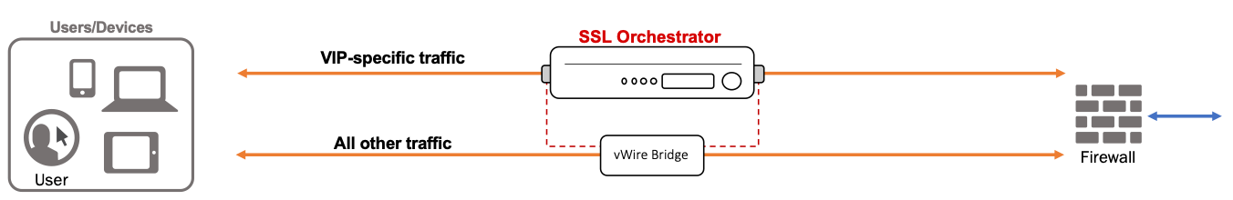
Figure 89: SSL Orchestrator Layer 2 Logical Flow (Diagram)
6.1.5. Traffic flow through the service chain
An SSL Orchestrator service chain, or more specifically a “dynamic service chain”, is a construct that allows traffic to be directed to independently addressable security services based on traffic rules. Unlike a traditional “daisy chain”, where traffic enters one device, leaves that device to the next device, leaves that device to the next device, etc., the dynamic service chain allows devices to be targeted independently.
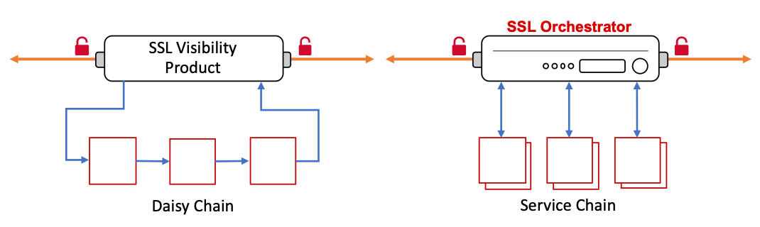
Figure 90: Comparison of Daisy Chaining vs. Service Chaining
The service chaining and independent addressability of services also provides the following benefits:
Independent scaling - Security products can be load balanced, scaled up/down, monitored, and potentially bypassed on failure, independent of other services in the security stack. As security rules can be defined to target different types of traffic, it may be advantageous that some security devices are used for some of this traffic but not all. In a traditional daisy chain, all devices along the chain must be able to support the same capacity, regardless of their ability to actually inspect the traffic. In the dynamic service chain, services can be targeted so that “interesting” traffic is only forwarded to services that care about it. You then have the option to scale the security devices independently and in accordance with their share of the inspectable traffic flows.
Independent control - Consider the typical scenario when a security product in the daisy chain stack needs to be updated or replaced. Normally this would require some window of time to take services offline, creating an outage, and probably a long night of troubleshooting. In the dynamic service chain, services are independently addressed, load balanced and monitored. To remove a service from the security stack simply means to disable its service pool member. To completely remove a service, remove it from the service chain and optionally delete. All of this can be done in real time with no outage.
Or consider what it usually takes to introduce a new security product into an environment. This will almost always involve testing in a lab with lab traffic, requesting maintenance time to place in production, and then several hours of nail biting to see whether or not the product breaks with previously untested production traffic. In the dynamic service chain, you can simply attach a security service, create a service chain with that service (and other production services), and then create a security rule that defines a subset of production traffic and assigns this service chain. Your segment of production traffic is then able to test the viability of the device without an outage or maintenance window.
This flexibility is made possible by a set of components inside the F5 full proxy architecture that are described below. Each security service type is unique in this respect, but we will focus on the easiest, the inline layer 3 service. The SSL Orchestrator components of an inline layer 3 service include the following objects:
Internal “service” virtual servers - All inline services start with an internal “entry” virtual server. Decrypted traffic is passed to this entry virtual, which then load balances the traffic to a pool. In the case of an inline layer 3 service, the pool members are the “to-service” IP addresses of the individual service devices, as defined in the service configuration. For all of the inline services, there also exists a “return” virtual server that catches the traffic on the other side of the service’s “from-service” interface. The entry virtual is an “internal” type and receives traffic from a targeting function. The destination virtual is a standard wildcard (0.0.0.0/0) listening on the service’s from-service VLAN.
For inline layer 3 services, the entry virtual server uses a resource pool consisting of the inline layer 3 service’s interface IP address on the to-service VLAN.
For inline HTTP services, the configuration is the same as the inline layer 3 service, except that the configuration expects proxying of the traffic (explicit or transparent proxy), so must handle packet signaling differently.
For inline layer 2 services, the entry virtual server uses a resource pool consisting of self-IPs from the BIG-IP from-service VLAN on the other side of the inline layer 2 service. This layer 3 routing across the layer 2 service provides the additional benefits of active load balancing and monitoring of layer 2 services.
For TAP services, the configuration contains a single entry virtual server (no destination virtual).
For ICAP services, the configuration contains a single entry virtual server and separate ICAP REQMOD and RESPMOD internal virtual servers.
Connector profile - The Connector profile defines the entry virtual for traffic flows, a timeout value, and what should happen when a service fails its monitor. Essentially, traffic flow targets a security service by assigning a Connector. The Connector is a proxy chain component, sitting between the OSI layer 6 (SSL) and layer 7 (application) protocol filters, enabling decrypted traffic to be “tapped” off of the original proxy connection. The SSL Orchestrator service chain dynamically assigns Connector profiles to a flow based on the matching traffic rule and defined service chain.
Service profile - The Service profile defines the type of security service. This specifically informs the configuration on how to signal the traffic through the security device. The same service profile is applied to both virtual servers of an inline device (layer 2, layer 3 and HTTP).
Split-Session profiles - The Split-Session profiles define how signaling is conveyed for a given service type. There are separate client and server Split-Session profiles, one for the entry virtual server, and the other for the destination virtual server, respectively. The Split-Session profiles establish a secure channel between the entry and return virtual servers to communicate the signaling information.
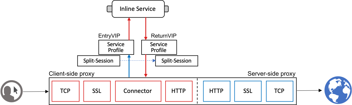
Figure 91: Service-Split-Session-Connector Profiles and Service Virtual Servers
Traffic flow through a security service begins with the Connector assignment, which targets the respective entry virtual server. That virtual server either load balances to or through a security device and traffic flow lands on the destination virtual server on the other side (for inline security devices). The Service and Split-Session profiles accordingly pass signaling information from entry to destination to relay and maintain flow context through the service chain.