Unofficial - F5 Certification Exam Prep Material > F5 301B - BIG-IP LTM Specialist: Maintain and Troubleshoot Exam Study Guide - Created 11/01/19 Source | Edit on
Section 3 - Identify and Resolve LTM Device Issues
Objective - 3.01 Interpret log file messages and/or command line output to identify LTM device issues
3.01 - Interpret log file messages to identify LTM device issues
https://support.f5.com/csp/article/K14426
Identifying hardware issues
This can be a very broad topic because there are a very large number of hardware errors that can occur. Every log message will contain an ID number and will be followed by a description in the log.
Example:
Back in version 11.4 the pendsect feature was added to the TMOS software that periodically checks for pending sector alerts and resolves them. The pendsect feature is configured to run daily. The pendsect messages provide improved disk error detection and correction. The system logs the pendsect messages to the /var/log/user.log file.
When the pendsect process runs and no errors are detected or corrected, the system logs messages that appear similar to the following example:
warning pendsect[21788]: pendsect: /dev/sdb no Pending Sectors detected
When the pendsect process detects and corrects an error, the system logs messages that appear similar to the following example:
warning pendsect[19772]: Recovered LBA:230000007
warning pendsect[19772]: Drive /dev/sda partition UNKNOWN
warning pendsect[19772]: File affected NONE
When the pendsect process detects an error and is unable to correct the error, the system logs messages that appear similar to the following example:
warning pendsect[20702]: seek(1) error[25] recovery of LBA:226300793 not complete
warning pendsect[20702]: Drive: /dev/sda filesystem type: Undetermined
warning pendsect[20702]: File affected: NONE
Recommended Actions
If pendsect reports an uncorrectable error, or if you suspect a possible disk failure, you can perform the End-User Diagnostic (EUD) SMART test to test the drive. For information about the EUD utility, and links to the latest release notes, refer to K7172: Overview of the End User Diagnostics software.
Beginning in BIG-IP 11.4.0, you can also use the platform_check command to collect the SMART test data from the drive. The disk portion of the command output indicates a Pass or Fail status for the drive and logs detailed information to the /var/log/platform_check file.
3.01 - Interpret the qkview heuristic results
Troubleshooting using iHealth
The F5 iHealth server is a tool that helps you troubleshoot potential issues. It does this by analyzing configuration, logs, command output, password security, license compliance, and so on.
From F5 BIG-IQ Centralized Management, you can create a snapshot of a configuration in the form of a QKView file and then upload it to the F5 iHealth server. The file is compared to the iHealth database, which contains known issues, common configuration errors, and F5 published best practices. F5 returns an iHealth report you can use to identify any potential issues that you need to attend to.
Troubleshoot potential issues by viewing an iHealth device report
After you upload a QKView file for one or more BIG-IP devices, the F5 iHealth server returns a device report.
Review the device report so you can address any potential issues or vulnerabilities. From the report, you can access and sort heuristics associated with a device.
- At the top of the screen, click Monitoring.
- On the left, click REPORTS > Device > iHealth > Device Reports .
- Click the Open link next to the report you want to view.
- To sort the heuristics for a report you’ve opened, select an option from the All Importance and/or the All Flags list.
- You can add a flag to a specific heuristic by selecting the check box next to it, and selecting a flag from the All Flags list.
- To view more details about a specific heuristic, click on its link.
- To view an article on the AskF5 Knowledge Center database to get more information about this heuristic, click the solution link.
3.01 - Identify appropriate methods to troubleshoot NTP
https://support.f5.com/csp/article/K14120
NTP
NTP is a protocol for synchronizing the clocks of computer systems over the network. On BIG-IP systems, accurate timestamps are essential to guarantee the correct behavior of a number of features. While in most cases it is sufficient to configure a couple of time servers that the BIG-IP system will use to update its system time, it is also possible to define more advanced NTP configurations on the BIG-IP system.
https://support.f5.com/csp/article/K10240
When the BIG-IP system clock is not showing the correct time zone, or the date and time is not synchronized correctly, this could be caused by incorrect NTP configuration or a communication issue with a valid NTP peer server. The procedures in this article show how you may check the NTP daemon process, verify the NTP configuration, query the NTP peer server, and check the network connectivity to the NTP peer server.
When verifying the NTP peer server communication, you can use the ntpq utility. The command generates output with the fields that are explained in the following table.
| Field | Definition |
|---|---|
| prefix to the remote field |
|
| remote | The remote field is the address of the remote peer. |
| refid | The refid field is the Reference ID which identifies the server or reference clock with which the remote peer synchronizes, and its interpretation depends on the value of the stratum field (explained in the st definition). For stratum 0 (unspecified or invalid), the refid is an ascii value used for debugging. Example: INIT or STEP. For stratum 1 (reference clock), the refid is an ascii value used to specify the type of external clock source. Example: NIST refers to NIST telephone modem. For strata 2 through 15, the refid is the address of the next lower stratum server used for synchronization. |
| st | The st field is the stratum of the remote peer. Primary servers (servers with an external reference clock such as GPS) are assigned stratum 1. A secondary NTP server which synchronizes with a stratum 1 server is assigned stratum 2. A secondary NTP server which synchronizes with a stratum 2 server is assigned stratum 3. Stratum 16 is referred to as “MAXSTRAT,” is customarily mapped to stratum value 0, and therefore indicates being unsynchronized. Strata 17 through 255 are reserved. |
| t | The t field is the type of peer: local, unicast, multicast, or broadcast. |
| when | The when field is the time since the last response to a poll was received (in seconds). |
| poll | The poll field is the polling interval (in seconds). This value starts low (example: 64) and over time, as no changes are detected, this polling value increases incrementally to the configured max polling value (example: 1024). |
| reach | The reach field is the reachability register. The octal shift register records results of the last eight poll attempts. |
| delay | The delay field is the current estimated delay; the transit time between these peers in milliseconds. |
| offset | The offset field is the current estimated offset; the time difference between these peers in milliseconds. |
| jitter | The jitter field is the current estimated dispersion; the variation in delay between these peers in milliseconds. |
3.01 - Identify license problems based on the log file messages and statistics
https://support.f5.com/kb/en-us/products/big-ip_ltm/releasenotes/related/log-messages.html#A01010044
Licensing based log messages
There are multiple types of log messages that could occur around licensing.
01010044 : "%s feature %s licensed"
Location:
/var/log/ltm
Conditions:
This message does not necessarily denote a problem. It displays the license status of BIG-IP device’s component.
When status for component X is “licensed”, this log displays the message:
Component X is licensed.
When the component is not licensed, the message is:
Component X is NOT licensed.
Impact:
If the message is “Component X is licensed”, there is no impact. It is an informative message.
If the message is “Component X is not licensed”, then you cannot use the mentioned component/feature.
Recommended Action:
If you want to use a component that is not currently licensed, you need to activate the license.
When the system statistics show bandwidth of the licensed feature is running at the max level you may see logs reflecting that the system is exceeding the licensed limit.
01010045 : Bandwidth utilization is %d Mbps, exceeded %d%% of Licensed %d Mbps
Location:
/var/log/ltm
Conditions:
This message appears when the system is using more bandwidth that it was licensed to use.
Impact:
The system will not perform at its full potential with a limited license.
Recommended Action:
A license with better bandwidth utilization would stop this message from appearing.
Objective - 3.02 Identify the appropriate command to use to determine the cause of an LTM device problem
3.02 - Identify hardware problems based on the log file messages and statistics
https://support.f5.com/kb/en-us/products/big-ip_ltm/releasenotes/related/log-messages.html
Identify Hardware Problems
This can be a very broad topic because there are a very large number of hardware errors that can occur. Every log message will begin with an ID number and will be followed by a description in the log. The list of possible log messages is long and memorizing them is not required, but understanding how to read the messages and where logs can be found are important. You will find many hardware related log messages in /var/log/ltm and when you see LCD in the location that means it will echo to the LCD screen of the device.
Log Message Example
012a0028 : %s
Location:
/var/log/ltm, LCD
Conditions:
AOM has indicated that a temperature sensor has crossed a ‘warning’ threshold.
Impact:
Integrity of the hardware could be at risk if overheating is not mitigated.
Recommended Action:
- Check the fan status of the unit using ‘tmsh show sys hardware’.
- Inspect the LCD and/or /var/log/ltm for any fan related problems.
- Ensure that ambient room temperature in which the device is located has sufficient cooling.
- Inspect /var/log/ltm and /var/log/sel around the time of the message for any additional indications as to why the unit might be starting to overheat.
You can also correlate information in the performance statistics to hardware errors in the logs.
3.02 - Identify resource exhaustion problems based on the log file messages and statistics
https://support.f5.com/csp/article/K14813
Identify resource exhaustion problems
There can be many types of resource exhaustion issues to troubleshoot. This example is based on memory exhaustion due to a SYN flood. Your exam may contain other types.
Detecting DoS and DDoS attacks
The BIG-IP system provides methods to detect ongoing or previous DoS and DDoS attacks on the system. To detect these attacks, perform the following procedures:
The BIG-IP SYN cookie feature protects the system against SYN flood attacks and allows the BIG-IP system to maintain connections when the SYN queue begins to fill up during an attack.
Reviewing SYN cookie threshold log messages
The BIG-IP system may log one or more error messages that relate to SYN cookie protection to the /var/log/ltm file. Messages that relate to SYN cookie protection appear similar to the following examples:
When the virtual server exceeds the SYN Check Activation Threshold, the system logs an error message similar to the following example:
warning tmm5[18388]: 01010038:4: Syncookie threshold 0 exceeded,
virtual = 10.11.16.238:80
When hardware SYN cookie mode is active for a virtual server, the system logs an error message similar to the following example:
notice tmm5[18388]: 01010240:5: Syncookie HW mode activated, server
= 10.11.16.238:80, HSB modId = 1
When hardware SYN cookie mode is not active for a virtual server, the system logs an error message similar to the following example:
notice tmm5[18388]: 01010241:5: Syncookie HW mode exited, server =
10.11.16.238:80, HSB modId = 1 from HSB
Reviewing maximum reject rate log messages
The tm.maxrejectrate db key allows you to adjust the number of TCP RSTs or ICMP unreachable packets that the BIG-IP system sends in response to incoming client-side or server-side packets that cannot be matched with existing connections to BIG-IP virtual servers, self IP addresses, or Secure Network Address Translations (SNATs). A high number of maximum reject rate messages may indicate that the BIG-IP system is experiencing a DoS/DDoS attack.
The BIG-IP system may log error messages that relate to SYN cookie protection to the /var/log/ltm file. Messages that relate to SYN cookie protection appear similar to the following examples:
When the number of packets that match a virtual IP address or a self IP address exceeds the tm.maxrejectrate threshold, but the packets specify an invalid port, the system stops sending RST packets in response to the unmatched packets and logs an error message to the /var/log/ltm file that appears similar to the following example:
011e0001:4: Limiting closed port RST response from 299 to 250
packets/sec
When the number of packets that match a virtual address and port, or a self IP address and port, exceeds the tm.maxrejectrate threshold, but the packet is not a TCP SYN packet and does not match an established connection, the system stops sending RST packets in response to the unmatched packets. The system also logs an error message to the /var/log/ltm file that appears similar to the following example:
011e0001:4: Limiting open port RST response from 251 to 250
packets/sec
3.02 - Identify connectivity problems based on the log files
https://support.f5.com/csp/article/K53419416
Virtual Server Processing Order
There can be many types of connectivity issues to troubleshoot. This Error Message example is based on connectivity failure between an HA pair. Your exam may contain other types.
Error Message
01071431:5: Attempting to connect to CMI peer <IP address> port <port>
In this error message, note the following:
- <IP address> is the remote BIG-IP system’s configured failover IP address, used for failover operations.
- <port> is the remote BIG-IP system’s configured failover TCP service port, used for failover operations.
For example:
01071431:5: Attempting to connect to CMI peer 192.168.10.100 port 6699
Message Location
You may encounter this message in the following location:
- /var/log/ltm
Description
This message occurs when all of the following conditions are met:
- You have multiple BIG-IP systems in a high availability (HA) configuration.
- The master control process daemon (mcpd) starts and attempts to connect to a peer BIG-IP system in the trust domain or general network issues exist, such as routing or switching failures, which prevent connectivity between BIG-IP systems in the trust domain.
A trust domain is a collection of BIG-IP devices that trust each other. The devices can synchronize, fail over their BIG-IP configuration data, and exchange status and failover messages on a regular basis.
Impact
If this error message appears unaccompanied by other messages, then there is no impact on the BIG-IP system. If other messages are logged along with this error message, you can use those messages to troubleshoot the impact on the BIG-IP system. For example, if a general network issue occurs and the local BIG-IP system is unable to connect to a remote peer BIG-IP system, a message appearing similar to the following example is logged:
01071431:5: Attempting to connect to CMI peer 192.168.10.100 port 6699

0107142f:3: Can't connect to CMI peer 192.168.10.100, port:6699, Transport endpoint is not connected
Recommended Actions
If logged messages indicate that the BIG-IP system is impacted, ensure that the self IP addresses for the BIG-IP devices in the cluster are correct and that the network allows proper connectivity between the devices.
3.02 - Determine the appropriate log file to examine to determine the cause of the problem
https://support.f5.com/csp/article/K16197
Logging
BIG-IP log files include important diagnostic information about the events that are occurring on the BIG-IP system. Some of the events pertain to the Linux host. For example, the Linux host generates system messages that pertain to the Linux host operating system, including messages that are logged during system startup, and information logged by the background daemons that run on the system. Other events are specific to the BIG-IP operating system. For example, the BIG-IP operating system generates messages that pertain to local and global traffic events, and configuration changes (audit logging).
Local logging
By default, the BIG-IP system logs events locally and stores messages in the /var/log directory. For BIG-IP events, the system routes messages from the errdefs subsystem through syslog-ng to the local log files. For non-BIG-IP events, the system routes messages directly through syslog-ng to the local log files. In addition, you can configure the system to use the high-speed logging mechanism (HSL) to store the logs in either the syslog or the MySQL database.
Remote logging
You can configure the system to use the HSL mechanism to log messages to a pool of remote log servers. If the BIG-IP system processes a high volume of traffic or generates an excessive amount of log files, F5 recommends that you configure remote logging.
BIG-IP log types
Each type of event is stored locally in a separate log file, and the information stored in each log file varies depending on the event type. All log files for these event types are in the /var/log directory.
| Type | Description | Log file |
|---|---|---|
| audit | The audit event messages are messages that the BIG-IP system logs as a result of changes to the BIG-IP system configuration. Logging audit events is optional. | /var/log/audit |
| boot | The boot messages contain information that is logged when the system boots. | /var/log/boot.log |
| cron | When the cron daemon starts a cron job, the daemon logs the information about the cron job in this file. | /var/log/cron |
| daemon | The daemon messages are logged by various daemons that run on the system. | /var/log/daemon.log |
| dmesg | The dmesg messages contain kernel ring buffer information that pertains to the hardware devices that the kernel detects during the boot process. | /var/log/dmesg |
| GSLB | The GSLB messages pertain to global traffic management events. | /var/log/gtm |
| httpd | The httpd messages contain the Apache Web server error log. | /var/log/httpd/httpd_errors |
| kernel | The kernel messages are logged by the Linux kernel. | /var/log/kern.log |
| local traffic | The local traffic messages pertain specifically to the BIG-IP local traffic management events. | /var/log/ltm |
| The mail messages contain the log information from the mail server that is running on the system. | /var/log/maillog | |
| packet filter | The packet filter messages are those that result from the use of packet filters and packet-filter rules. | /var/log/pktfilter |
| security | The secure log messages contain information related to authentication and authorization privileges. | /var/log/secure |
| system | The system event messages are based on global Linux events, and are not specific to BIG-IP local traffic management events. | /var/log/messages |
| TMM | The TMM log messages are those that pertain to Traffic Management Microkernel events. | /var/log/tmm |
| user | The user log messages contain information about all user level logs. | /var/log/user.log |
| webui | The webui log messages display errors and exception details that pertain to the Configuration utility. | /var/log/webui.log |
Log message format
Log messages are formatted differently depending on the type of log and the component that generated the event messages. The log formats are discussed in the following sections.
Local traffic log message format
The local traffic (ltm) log messages generated by the BIG-IP system include the following types of information:
<time stamp> <host name> <level> <service[pid]> <message code> <message text>
- Time stamp: The time/date that the system logged the message
- Host name: The host name of the BIG-IP system that generated the message
- Service: The name of the service (and process ID) that generated the message
- Message code: The code that is associated with the message. The code is comprised of the following sub-codes:
- Product Code: The first two hex digits form the product code. For example, 0x01 is the BIG-IP product code.
- Subset Code: The third and fourth hex digits are the subset code. For example, 0x2a is the subset code for LIBHAL.
- Message Number: The next four digits form the message number within a module.
- Severity Level: The last digit between the colon symbols is the severity level, with 0 being the highest severity level.
- Message text: The description of the event that caused the system to log the message.
Linux host log message format
Most log messages generated by the Linux host include a format similar to the local traffic logs with the exception of the message code.
Audit log message format
The audit log messages generated by the BIG-IP system include the following types of information:
<time stamp> <host name> <level> <service[pid]> <message code> <user> <event>
- Time stamp: The time/date that the system logged the message
- Host name: The host name of the BIG-IP system that generated the message
- Service: The name of the service (and process ID) that generated the message
- Message code: The code that is associated with the message (refer to the previous Local traffic log message format section for Message code sub-code definitions)
- User: The name of the user who made the configuration change, the user’s partition, and the user’s permission level
- Event: The description of the configuration change or event that caused the system to log the message
Objective - 3.03 Analyze performance data to identify a resource problem on an LTM device
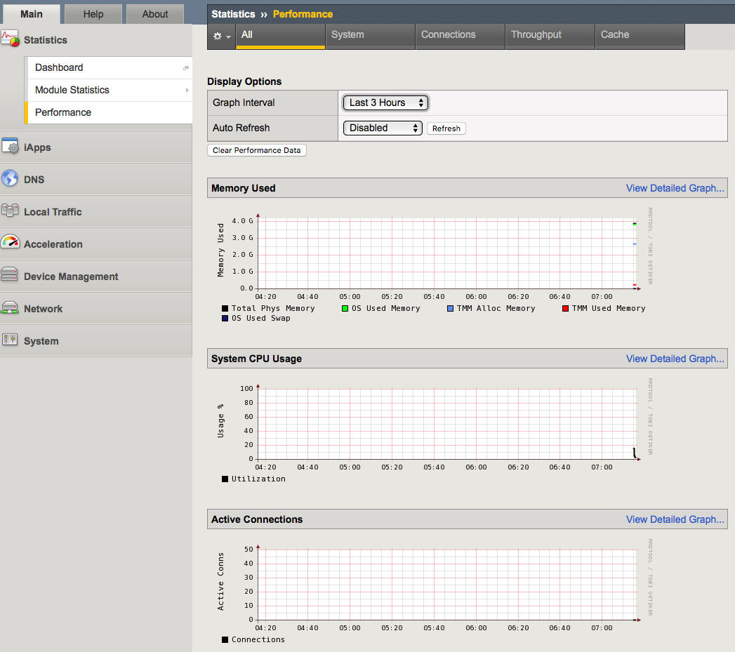
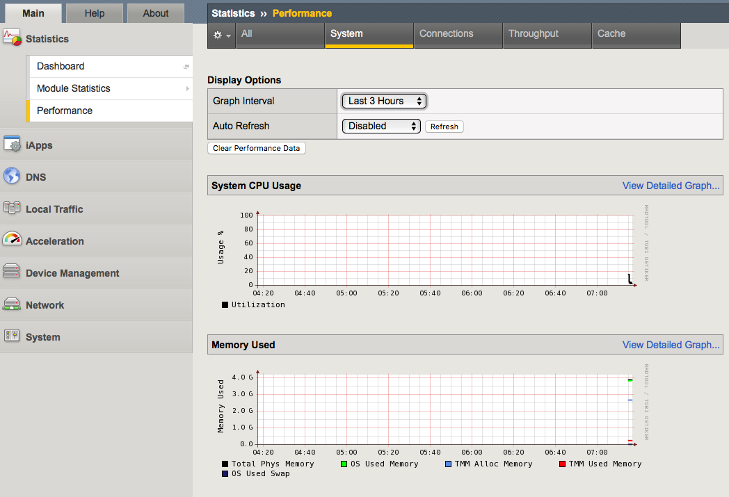
3.03 - Analyze performance data to identify a resource problem on an LTM device
All of the statistical information related to the LTM’s performance can be seen by navigating in the GUI to Statistics > Performance.
https://support.f5.com/csp/article/K15468
Understanding BIG-IP CPU usage
The Traffic Management Microkernel (TMM) processes all load-balanced traffic on the BIG-IP system. TMM runs as a real-time user process within the BIG-IP operating system (TMOS). CPU and memory resources are explicitly provisioned in the BIG-IP configuration.
Understanding BIG-IP CPU usage
The following factors influence the manner in which TMM uses the CPU:
- The number of processors installed in the BIG-IP system
- The BIG-IP version
- The modules for which the BIG-IP system is licensed
CPU utilization on single CPU, single core systems
CPU resources are explicitly provisioned in the BIG-IP configuration. When TMM is idle or processing low volumes of traffic, TMM yields idle cycles to other processes.
CPU utilization on multi-CPU / multi-core systems
Prior to BIG-IP 11.5.0, each logical CPU core is assigned a separate TMM instance, and each core processes both data plane (TMM-specific) tasks and control plane (non-TMM-specific) tasks.
Beginning in BIG-IP 11.5.0, data plane tasks and control plane tasks use separate logical cores on systems with Intel Hyper-Threading Technology (HT Technology) CPUs. Even-numbered logical cores (hyperthreads) are allocated to TMM, while odd numbered cores are available for other processes.
Using the tmsh utility to view TMM CPU usage
Log in to the TMOS Shell (tmsh) by typing the following command:
tmsh
To display TMM CPU utilization and other statistical information for TMM instances, type the following tmsh command:
show /sys tmm-info
For example, the following tmsh command is showing CPU usage for TMM 0.0 (Output truncated):
Sys::TMM: 0.0
--------------------------
CPU Usage Ratio (%)
Last 5 Seconds 3
Last 1 Minute 3
Last 5 Minutes 2
Note
System CPU utilization is calculated by the following sets of values:
Average over all TMM CPUs (all even CPUs)
Average over ‘all odd CPUs except the last one’ (The reason for leaving out the last CPU is due to an analysis plane that was spiking the last CPU numbers.)
The higher of these values are presented as the overall system CPU usage.
https://support.f5.com/csp/article/K16419
Understanding BIG-IP Memory usage
When administering a BIG-IP system, it is important to understand how the system allocates memory. In general, BIG-IP memory usage falls into the following categories:
- Traffic Management Microkernel (TMM) memory usage
- Linux host memory usage
- Swap usage
TMM runs as a real-time user process within the Linux host operating system. The BIG-IP system statically assigns memory resources to TMM and potentially to other module-related processes, depending on module provisioning. The remaining memory is available for all other Linux host processes.
The BIG-IP system creates swap usage space during software installation on disk. Swap space is available to the Linux kernel.
TMM memory usage
The BIG-IP data plane includes one or more TMM processes to manage traffic on the BIG-IP system. The BIG-IP system statically assigns memory resources to TMM.
The following information summarizes TMM memory:
- The BIG-IP system assigns a dedicated pool of memory to each TMM process.
- TMM memory is not available for the Linux kernel to reassign to other host processes. The system never considers TMM memory as available.
- TMM memory cannot be swapped to disk.
- The TMM memory management subsystem allocates and clears memory pages in the following manner:
- TMM allocates static memory to hash tables (for example, the connection flow table).
- TMM dynamically allocates memory pages for temporary objects (for example, persistence records and buffered connection data).
- Memory sweepers periodically reap unused memory as needed from TMM objects.
- When possible, TMM caches dynamic allocations to improve performance when new objects require the same allocations.
Linux memory usage
The system may allocate remaining memory to other processes on the Linux host and kernel threads.
The following information summarizes Linux host memory usage:
- Linux allocates most available memory to buffers and disk caching, which gives the appearance of high memory usage but allows the system to run more efficiently.
- Linux utilities, such as top and free, may report that only a small amount of memory is free. This is normal behavior; cached memory can be reclaimed quickly if a program needs memory.
- To see memory used by buffers and disk caching, view the -/+ buffers/cache row where top and free report these memory structures. Add these values to the reported amount of free memory to estimate the total amount of physical memory the processes are not currently using.
- The Linux kernel sometimes copies memory pages to swap. This is known as swapping memory.
Swap memory usage
The following information summarizes swap memory usage:
- It is normal for a Linux system, including the BIG-IP system, to use a small amount of swap. The Linux kernel sometimes prefers to swap idle processes memory to disk so that more physical memory is available for more active processes, buffers, and caches.
- Physical memory is much faster than swap, and prioritizing buffers and caches allows the kernel to optimize performance of disk-heavy processes such as databases.
- A higher percentage of swap use is normal when provisioned modules make heavy use of the disk.
- Excessive swap usage may be a sign that the system is experiencing memory pressure. You should investigate in the following cases:
- The system uses a very high percentage of swap memory.
- The percentage of swap memory usage increases over time.
Understanding BIG-IP memory statistics
You can view BIG-IP memory statistics using BIG-IP utilities or Linux command line utilities. It is normal for Linux utilities, such as top and free, to report a small amount of free memory. This expected behavior occurs due to Linux disk caching. F5 recommends that you use the Configuration utility or the TMOS Shell (tmsh) to view memory statistics on the BIG-IP system.
You can view BIG-IP memory statistics, including TMM memory usage, other (Linux) memory usage, swap usage, and memory allocated to TMM hash tables and cache objects. To do so, use the following utilities:
- tmsh show /sys memory
- Configuration utility: Statistics > Module Statistics > Memory
Memory statistics (BIG-IP 10.x - 11.5.4)
In BIG-IP 10.x - 11.5.4, the Configuration utility tmsh report memory allocated to buffers and caches as used memory. As a result, it may appear that the host system is using all available memory. The system reports memory statistics in the following ways:
- System Memory
- Host Total: The amount of memory available to Linux or non-TMM processes.
- Host Used: The amount of memory in use by Linux or non-TMM processes.
- TMM Total: The amount of memory available to TMM processes.
- TMM Used: The amount of memory in use by TMM processes for traffic management.
- Subsystem memory/memory pool name
- Indicates the name and memory utilization of TMM hash tables and cache objects.
Objective - 3.04 Given a scenario, determine the cause of an LTM device failover
3.04 - Explain the effect of network failover settings on the LTM device
What triggers failover?
The BIG-IP system initiates failover according to any of several events that you define. These events fall into these categories:
System fail-safe
With system fail-safe, the BIG-IP system monitors various hardware components, as well as the heartbeat of various system services. You can configure the system to initiate failover whenever it detects a heartbeat failure.
Gateway fail-safe
With gateway fail-safe, the BIG-IP system monitors traffic between an active BIG-IP system in a device group and a pool containing a gateway router. You can configure the system to initiate failover whenever some number of gateway routers in a pool of routers becomes unreachable.
VLAN fail-safe
With VLAN fail-safe, the BIG-IP system monitors network traffic going through a specified VLAN. You can configure the system to initiate failover whenever the system detects a loss of traffic on the VLAN and the fail-safe timeout period has elapsed.
HA groups
With an HA group, the BIG-IP system monitors trunk, pool, or cluster health to create an HA health score for a device. You can configure the system to initiate failover whenever the health score falls below configurable levels.
Auto-failback
When you enable auto-failback, a traffic group that has failed over to another device fails back to a preferred device when that device is available. If you do not enable auto-failback for a traffic group, and the traffic group fails over to another device, the traffic group remains active on that device until that device becomes unavailable.
3.04 - Explain the relationship between serial and network failover
https://support.f5.com/csp/article/K2397
Network Failover
Network failover is based on heartbeat detection where the system sends heartbeat packets over the internal network.
The system uses the primary and secondary failover addresses to send network failover heartbeat packets. For more information about the BIG-IP mirroring and network failover transport protocols, refer to the following articles:
- K9057: Service port and protocol used for BIG-IP network failover
- K7225: Transport protocol used for BIG-IP connection and persistence mirroring
The BIG-IP system considers the peer down after the Failover.NetTimeoutSec timeout value is exceeded. The default value of Failover.NetTimeoutSec is three seconds, after which the standby unit attempts to switch to an active state. The following database entry represents the default settings for the failover time configuration:
Failover.NetTimeoutSec = 3
Device Service Clustering (DSC) was introduced in BIG-IP 11.0.0 and allows many new features such as synchronization and failover between two or more devices. Network failover provides communication between devices for synchronization, failover, and mirroring and is required for the following deployments:
- Sync-Failover device groups containing three or more devices
- Active-active configurations between two BIG-IP platforms
- BIG-IP VIPRION platforms
- BIG-IP Virtual Edition
An active-active pair must communicate over the network to indicate the objects and resources they service. Otherwise, if network communications fail, the two systems may attempt to service the same traffic management objects, which could result in duplicate IP addresses on the network.
Network issues may cause BIG-IP systems to enter into active-active mode. To avoid this issue, F5 recommends that you dedicate one interface on each system to perform only failover communications and, when possible, directly connect these two interfaces with an Ethernet cable to avoid network problems that could cause the systems to go into an active-active state.
Important: When you directly connect two BIG-IP systems with an Ethernet cable, do not change the speed and duplex settings of the interfaces involved in the connection. If you do, depending on the BIG-IP software version, you may be required to use a crossover cable. For more information, refer to K9787: Auto MDI/MDIX behavior for BIG-IP platforms.
If you configure a BIG-IP high-availability pair to use network failover, and the hardwired failover cable also connects the two units, hardwired failover always has precedence; if network failover traffic is compromised, the two units do not fail over because the hardwired failover cable still connects them.
Hardwired failover
Hardwired failover is also based on heartbeat detection, where one BIG-IP system continuously sends voltage to another. If a response does not initiate from one BIG-IP system, failover to the peer occurs in less than one second. When BIG-IP redundant devices connect using a hardwired failover cable, the system automatically enables hardwired failover.
The maximum hardwired cable length is 50 feet. Network failover is an option if the distance between two BIG-IP systems exceeds the acceptable length for a hardwired failover cable.
Note: For information about the failover cable wiring pinouts, refer to K1426: Pinouts for the failover cable used with BIG-IP platforms.
Hardwired failover can only successfully be deployed between two physical devices. In this deployment, hardwired failover can provide faster failover response times than network failover.
Hardwired failover is only a heartbeat and carries no status information. Communication over the network is necessary for certain features to function properly. For example, Traffic Management Microkernel (TMM) uses the network to synchronize packets and flow state updates to peers for connection mirroring. To enable proper state reporting and mirroring, F5 recommends that you configure network failover in addition to hardwired failover.
3.04 - Differentiate between unicast and multicast network failover modes
https://support.f5.com/csp/article/K2397
Failover IP addresses
These are the IP addresses that you want the BIG-IP system to use when another device in the device group fails over to the local device. You can specify two types of addresses: unicast and multicast.
For appliance platforms, specifying two unicast addresses should suffice. For VIPRION platforms, you should also retain the default multicast address that the BIG-IP system provides.
The recommended unicast addresses for failover are:
- The self IP address that you configured for either VLAN HA or VLAN internal. If you created VLAN HA when you initially ran the Setup utility on the local device, F5 recommends that you use the self IP address for that VLAN. Otherwise, use the self IP address for VLAN internal.
- The IP address for the local management port.
https://support.f5.com/csp/article/K90231443
Secure Network Failover
When you configure BIG-IP device group members to use network failover, the systems communicate over the configured failover addresses. By default, the systems use UDP port 1026 for unicast network failover traffic.
You can configure the BIG-IP system to pass network failover traffic over a secure channel. When you enable the failover.secure db variable, the system protects the failover connections to peer devices using DTLS and certificate authentication. Configuring secure network failover traffic may be beneficial when network traffic is configured to pass over a public network.
You should be aware of the following when you configure the BIG-IP system to pass network failover traffic over a secure channel:
- Secure network failover requires that one or more unicast failover IP address is defined for device group members.
- Enabling secure network failover disables the multicast network failover feature.
3.04 - Identify the cause of failover using logs and statistics
https://support.f5.com/csp/article/K95002127
Reviewing the log files for failover messages
The BIG-IP system logs messages related to failover in the /var/log/ltm file and the /var/log/audit file. After you locate a log message that indicates a failover occurrence, you can review the log files surrounding the failover event to help determine the cause of the failover. To review log files related to failover issues, refer to the following commands:
Impact of procedure: Performing the suggested actions should not have a negative impact on your system.
To display the /var/log/ltm file, use a Linux command similar to the following example:
less /var/log/ltm
To display log messages related to the system transitioning to an active or standby state, use the grep or egrep commands to search for certain patterns in the /var/log/ltm file similar to the following example:
egrep -i 'active|standby' /var/log/ltm
To display the /var/log/audit log file, use a Linux command similar to the following example:
less /var/log/audit
To display log messages related to the system administratively transitioning to a standby state, use the following egrep command to search for patterns related to the device being placed in the standby state in the /var/log/audit file.
For example:
egrep -i 'cmd_sod go standby|sys failover standby' /var/log/audit
You may observe messages similar to the following:
| Active/Standby message | Description |
|---|---|
| 010c0019:5: Active | The device has transitioned to an active state. |
| 010c0053:5: Active for traffic group <traffic_group>. | The device has transitioned to active for the specified traffic group. |
| 010c0018:5: Standby | The device has transitioned to a standby state. |
| 010c0052:5: Standby for traffic group <traffic_group> | The device has transitioned to active for the specified traffic group. |
| 010c0026:5: Failover condition, active attempting to go standby | The device has encountered a failover condition and is attempting to transition to a standby state. |
| 01070417:6: AUDIT - user admin - RAW: Request to run /usr/bin/cmd_sod go standby<traffic group> GUI. | User admin requested standby using the Configuration utility. |
| 01420002:5: AUDIT - pid=30246 user=root folder=/Common module=(tmos)# status=[Command OK] cmd_data=run sys failover standby | User admin requested standby using tmsh. |
To display log messages related to failover or fail-safe, use the grep or egrep commands to search for certain patterns in the /var/log/ltm file. For example:
egrep -i 'failover|failsafe' /var/log/ltm
You may observe messages similar to the following:
| Failover/Fail-safe message | Description |
|---|---|
| 010c0026:5: Failover condition, active attempting to go standby | The device has encountered a failover condition and is attempting to transition to a standby state. |
| 01140029:4: HA pool_memb_down <pool> fails action is failover | A component has detected an HA failure condition and is requesting the system take corrective action. |
| 010c002b:5: Traffic group <traffic_group> received a targeted failover command for <IP_addr> | The active device has received a failover command that was issued by an administrator. |
| 01140029:5: HA daemon_heartbeat <daemon> fails action is failover and restart | The noted daemon failed to update its heartbeat signal, causing a failover action. |
| 01140043:0: Ha feature nic_failsafe reboot requested | The system has detected an issue with the High-Speed Bridge (HSB) data path and has triggered a reboot action. |
| 01010023:2: Switchboard failsafe action indicated by <daemon>, exiting | The system has detected a switchboard issue and will execute the configured fail-safe action. |
To display log messages related to watchdog or overdog, use the grep or egrep commands to search for certain patterns in the /var/log/ltm file.
For example:
egrep -i 'watchdog|overdog' /var/log/ltm
You may observe messages similar to the following:
| Watchdog/overdog message | Description |
|---|---|
| 1140101:6: Overdog daemon shutdown | The watchdog daemon (overdog) has shut down and watchdog monitoring is no longer active. |
| 01140100:6: Overdog daemon startup | The HA watchdog is now active. |
| 01140103:5: Watchdog touch enabled with <number> seconds. | The system watchdog process (overdog) has initiated the hardware watchdog feature. |
| 01140104:5: Watchdog touch disabled | The hardware watchdog process (overdog) has disarmed the hardware watchdog and stopped periodic updates. |
Objective - 3.05 Given a scenario, determine the cause of loss of high availability and/or sync failure
3.05 - Explain how the high availability concepts relate to one another
https://support.f5.com/kb/en-us/solutions/public/13000/900/sol13946.html
DSC components
DSC provides the foundation for centralized management and high-availability features in BIG-IP 11.x, including the following components:
Device trust and trust domains
Device trust establishes trust relationships between BIG-IP devices through certificate-based authentication. Each device generates a device ID key and Secure Socket Layer (SSL) certificate upon upgrade or installation. A trust domain is a collection of BIG-IP devices that trust each other, and can synchronize and fail over their BIG-IP configuration data, as well as regularly exchange status and failover messages.
When the local BIG-IP device attempts to join a device trust with a remote BIG-IP device, the following applies:
If the local BIG-IP device is added as a peer authority device, the remote BIG-IP device presents a certificate signing request (CSR) to the local device, which then signs the CSR and returns the certificate along with its CA certificate and key.
If the local BIG-IP device is added as a subordinate (non-authority) device, the remote BIG-IP device presents a CSR to the local device, which then signs the CSR and returns the certificate. The CA certificate and key are not presented to the remote BIG-IP device. The subordinate device is unable to request other devices to join the device trust.
Device groups
A device group is a collection of BIG-IP devices that reside in the same trust domain and are configured to securely synchronize their BIG-IP configuration and failover when needed. Device groups can initiate a ConfigSync operation from the device group member with the desired configuration change. You can create two types of device groups:
A Sync-Failover device group contains devices that synchronize configuration data and support traffic groups for failover purposes.
A Sync-Only device group contains devices that synchronize configuration data, but do not synchronize failover objects and do not fail over to other members of the device group.
Traffic groups
A traffic group represents a collection of related configuration objects that are configured on a BIG-IP device. When a BIG-IP device becomes unavailable, a traffic group can float to another device in a device group.
Folders
A folder is a container for BIG-IP configuration objects. You can use folders to set up synchronization and failover of configuration data in a device group. You can sync all configuration data on a BIG-IP device, or you can sync and fail over objects within a specific folder only.
3.05 - Explain the relationship between device trust and device groups
https://support.f5.com/kb/en-us/solutions/public/13000/900/sol13946.html
Relationship between Device Trust and Device Group
For a Big-IP device to be added to a Device Group there must be an established trust between the devices in that Device Group and the new device. This is done through certificate-based authentication between the devices which establishes a Device Trust or trust domain.
3.05 - Identify the cause of ConfigSync failures
https://support.f5.com/kb/en-us/solutions/public/13000/900/sol13946.html
ConfigSync Failures
F5 introduced the DSC architecture in BIG-IP 11.x. DSC provides the framework for ConfigSync and other high availability (HA) features, such as failover for BIG-IP device groups.
Note: The DSC technology is also referred to as centralized management infrastructure (CMI).
This article provides steps to troubleshoot ConfigSync and the underlying DSC components. DSC and ConfigSync include the following elements:
CMI communication channel
The BIG-IP system uses SSL certificates to establish a trust relationship between devices. In a device trust, BIG-IP devices can act as certificate signing authorities, peer authorities, or subordinate non-authorities. When acting as a certificate signing authority, the BIG-IP device signs x509 certificates for another BIG-IP device that is in the local trust domain. The BIG-IP device for which a certificate signing authority device signs its certificate is known as a subordinate non-authority device. The BIG-IP system uses the following certificates to establish a secure communication channel.
| File name | Configuration utility location | Description |
|---|---|---|
| /config/ssl/ssl.crt/dtdi.crt | Device Management > Device Trust > Identity | The dtdi.crt is the identity certificate that is used by a device to validate its identity with another device. |
| /config/ssl/ssl.key/dtdi.key | Not applicable | The dtdi.key is the corresponding key file used by a device to validate its identity with another device. |
| /config/ssl/ssl.crt/dtca.crt | Device Management > Device Trust > Local Domain | The dtca.crt is the CA root certificate for the trust network. |
| /config/ssl/ssl.key/dtca.key | Not applicable | The dtca.key is the CA root key for the trust network. |
When the DSC components are properly defined, the device group members establish a communication channel to accommodate device group communication and synchronization. The CMI communication channel allows the mcpd process that runs on the device group member to exchange MCP messages and commit ID updates to determine which device has the latest configuration and is eligible to synchronize its configuration to the group. After the ConfigSync IP addresses are defined on each device, and the device group is created, the devices establish the communication channel, as follows:
- A user updates the configuration of a BIG-IP device group member using the Configuration utility or TMOS Shell (tmsh).
- The configuration change is communicated to the local mcpd process.
- The mcpd process communicates the new configuration and commit ID to the local TMM process.
- The local TMM process sends the configuration and commit ID update to remote TMM processes over the communication channel.
- The remote TMM process translates the port to 6699 and connects to its mcpd process.
- The remote mcpd process loads the new configuration into memory, and writes the configuration changes to the appropriate configuration files.
Automatic Sync
If you enable the Automatic Sync feature for a device group, the BIG-IP system automatically synchronizes changes to a remote peer system’s running configuration but does not save the changes to the configuration files on the peer device. This behavior is by design and recommended for larger configurations to avoid a long ConfigSync duration due to large configurations.
In some cases, you may want to configure Automatic Sync to update the running configuration and save the configuration to the configuration files on the remote peer devices. For information, refer to K14624: Configuring the Automatic Sync feature to save the configuration on the remote devices.
Beginning in BIG-IP 11.4.0, the Automatic Sync feature is available for both Sync-Only and Sync-Failover device groups. In addition, the automatic sync behavior can be configured to be either full or incremental. For more information, refer to K14809: Auto Sync is possible for Sync-Failover device groups.
Symptoms
DSC and ConfigSync issues may result in the following symptoms:
- Device group members have configuration discrepancies.
- The system displays status messages that indicate a synchronization or device trust issue.
- The BIG-IP system logs error messages related to device trust or the ConfigSync process.
Procedures
When you investigate a possible device service clustering or ConfigSync issue, you should first verify that the required configuration elements are set for all device group members. If the required elements are set, then attempt a ConfigSync operation. If ConfigSync fails, the BIG-IP system generates Sync status messages that you can use to diagnose the issue. Use the following procedures to troubleshoot DSC and ConfigSync:
Troubleshooting a ConfigSync operation
Attempt a ConfigSync operation to gather diagnostic information to help you troubleshoot ConfigSync/DSC issues. To troubleshoot the ConfigSync operation, perform the following procedures:
Verifying the required elements for ConfigSync/DSC
For DSC and ConfigSync to function properly, you must verify that required configuration elements are set. To do so, review the following requirement information.
| Requirement | Description | Configuration utility location | tmsh location |
|---|---|---|---|
| Licensing and provisioning | Device group members must have the same product licensing and module provisioning. Note: For exceptions, refer to the BIG-IP licensing and provisioning requirements section in *K8665: BIG-IP redundant configuration hardware and software parity requirements* |
System > License | tmsh show /sys license tmsh show /sys provision |
| Software versions | Device group members must run the same BIG-IP software version. | System > Software Management | tmsh show /sys software |
| Management IP | Each device must have a unique management IP address, netmask, and management route. | System > Platform | l ist /sys management-ip list /sys management-route |
| NTP | Network Time Protocol (NTP) is required for all device group members. | System > Configuration> Device > NTP | tmsh list /sys ntp servers |
| ConfigSync IP | Self IP addresses for ConfigSync must be defined and routable between device group members. F5 recommends that the addresses reside on a dedicated HA VLAN. | Device Management > Devices | tmsh list /cm device <device> configsync-ip |
| Failover IP | Self IP addresses for failover must be defined and routable between device group members (for Sync-Failover device groups). | Device Management > Devices | tmsh list /cm device <device> unicast-address |
| Ports | Device group members should be able to communicate over ports 443, 4353, 1026 (UDP), and 22 (recommended). BIG-IP ASM requires the following additional Policy Sync TCP ports: 6123-6128. | Not applicable | Not applicable |
| Device trust | Device trust must be established for device group members. | Device Management **> **Device Trust | tmsh show /cm device-group device_trust_group |
Reviewing common reasons for ConfigSync failures
If you experience ConfigSync issues after you first establish device trust, after rebooting, or upgrading, review the following common reasons for ConfigSync failure:
The devices have an IP address conflict
IP address conflicts are common causes of ConfigSync failure during initial device group setup. If the ConfigSync or failover IP address conflicts with another device, the systems will fail to establish a trust relationship, ConfigSync operations will fail, and the systems will fail to detect the active or next-active device. BIG-IP systems experiencing an IP address conflict log error messages to the /var/log/ltm file that appear similar to the following example:
warning tmm[11178]: 01190004:4: address conflict detected for
10.0.0.1 (00:0c:29:16:33:f6) on vlan 4093
One or more devices are not reachable on the network
Self IP addresses used for ConfigSync and failover must be routable between device group members. Prior to establishing device trust, make sure the devices are online and can communicate using the defined self IP addresses. For example, make sure you can ping the management IP address and ConfigSync IP addresses of other devices.
The software versions do not match
If you recently upgraded one of the device group members, you should verify that the other device group members are also upgraded and running the same software version. BIG-IP device group members must run the same BIG-IP software version for ConfigSync operations to work between group members; this includes the major, minor, and maintenance software version numbers. By default, the hotfix and point release version numbers are not required to match among device group members when performing ConfigSync operations.
The BIG-IP configuration fails to load
If you experience ConfigSync issues after upgrading or loading a UCS file on a device, verify whether the configuration failed to load. To do so, type the following command from the command line, correct reported validation errors, and attempt to reload the configuration:
tmsh load sys config verify
Viewing the commit ID updates
When you troubleshoot a ConfigSync issue, it is helpful to determine which device group member has the latest commit ID update and contains the most recent configuration. You can then decide whether to replicate the newer configuration to the group, or perform a ConfigSync operation that replicates an older configuration to the group, thus overwriting a newer configuration.
To display the commit ID and the commit ID time stamps for the device group, perform the following procedure:
Impact of procedure: Performing the following procedure should not have a negative impact on your system.
Log in to the BIG-IP command line.
To display the commit IDs for the device group, type the following command:
tmsh run /cm watch-devicegroup-device
Locate the relevant device group and review the cid.id and cid.time columns.
For example, the following output shows that the sync_test device group has three members, and device bigip_a has the latest configuration as indicated by the cid.id (commit ID number) and cid.time (commit ID timestamp) columns:
devices <devgroup [device   cid.id   cid.orig   cid.time   last_sync
20 21 sync_test   bigip_a   32731    bigip_a    14:27:00   : :
20 21 sync_test   bigip_b   1745     bigip_a    13:39:24   13:42:04
20 21 sync_test   bigip_c   1745     bigip_a    13:39:24   13:42:04
Note: Multiple devices with identical information are collapsed into a single row that displays in green.
- Perform steps 1 through 3 on all devices in the device group.
- Compare the commit ID updates for each device with each device group member. If the commit ID updates are different between devices, or a device is missing from the list, proceed to the Troubleshooting DSC section.
Verifying a ConfigSync operation
When troubleshooting a ConfigSync issue, attempt a ConfigSync operation and verify the sync status message. If the ConfigSync operation fails, the BIG-IP system generates a sync status message that you can use to diagnose the issue. To attempt a ConfigSync operation, perform one of the following three procedures:
Configuration utility
Impact of procedure: Performing the following procedure should not have a negative impact on your system.
- Log in to the Configuration utility.
- Navigate to Device Management > Overview.
- For Device Groups, click the name of the device group you want to synchronize.
- For Devices, click the appropriate device.
- Click the synchronization operation.
- Click Sync.
tmsh
Impact of procedure: Performing the following procedure should not have a negative impact on your system.
Log in to tmsh by typing the following command:
tmsh
To synchronize the configuration to the device group, use the following command syntax:
run /cm config-sync <option> <device_group>
For example, to synchronize the local device configuration to the device group, type the following command:
run /cm config-sync to-group <device_group>
Verifying the sync status
After you attempt the ConfigSync operation, you can verify the synchronization status messages and begin to troubleshoot the issue. To verify the synchronization status, refer to the following utilities.
| Utility | Page or command | Description |
|---|---|---|
| Configuration utility | Device Management > Overview | The Device Groups section displays the ConfigSync status for device groups. The Devices section displays the ConfigSync status for devices. |
| tmsh | tmsh show /cm sync-status | Displays the ConfigSync status of the local device and any recommended synchronization actions. |
Understanding sync status messages
The BIG-IP system displays ConfigSync status messages for device groups and specific devices. Common synchronization status messages are displayed in the following tables.
Synchronization status messages for device groups
The BIG-IP system displays a number of specific synchronization status messages for each device group. Use the following table to help you troubleshoot messages that you might encounter.
| Sync status | Summary | Details | Recommendation |
|---|---|---|---|
| Awaiting Initial Sync | The device group is awaiting the initial ConfigSync | The device group was recently created and has either not yet made an initial sync, or the device has no configuration changes to be synced. | Sync one of the devices to the device group. |
| Awaiting Initial Sync | hostname-1, hostname-2, etc. awaiting the initial ConfigSync | One or more device group members have not yet synced their data to the other device group members, or a device group member has not yet received a synchronization from another member. | Sync the device that has the most current configuration to the device group. |
| Changes Pending | Changes pending | One or more device group members have recent configuration changes that have not been synchronized to the other device group members. | Sync the device that has the most current configuration to the device group. |
| Changes Pending | There is a possible change conflict between hostname-1, hostname-2, etc. | There is a possible conflict among two or more devices because more than one device contains changes that have not been synchronized to the device group. | View the individual synchronization status of each device group member, and then sync the device that has the most current configuration to the device group. |
| Not All Devices Synced | hostname-1, hostname-2, etc. did not receive last sync successfully | One or more of the devices in the device group does not contain the most current configuration. | View the individual synchronization status of each device group member, and then sync the device that has the most current configuration to the device group. |
| Sync Failure | A validation error occurred while syncing to a remote device | The remote device was unable to sync due to a validation error. | Review the /var/log/ltm log file on the affected device. |
| Unknown | The local device is not a member of the selected device group | The device that you are logged in to is not a member of the selected device group. | Add the local device to the device group. |
| Unknown | Not logged in to the primary cluster member | The system cannot determine the synchronization status of the device group because you are logged in to a secondary cluster member instead of the primary cluster member. This status pertains to VIPRION systems only. | Use the primary cluster IP address to log in to the primary cluster member. |
| Unknown | Error in trust domain | The trust relationships among devices in the device group are not properly established. | On the local device, reset device trust and then re-add all relevant devices to the local trust domain. |
| None | X devices with Y different configurations | The configuration time for two or more devices in the device group differs from the configuration time of the other device group members. This condition causes one of the following synchronization status messages to appear for each relevant device: Device_name awaiting initial ConfigSync Device_name made last configuration change on date_time | Sync the device that has the most current configuration to the device group. |
Synchronization status messages for devices
The BIG-IP system displays a number of specific synchronization status messages for individual devices. Use the following table to help you troubleshoot messages that you might encounter.
| Sync status | Summary | Recommendation |
|---|---|---|
| Awaiting Initial Sync | The local device is waiting for the initial ConfigSync. The device has not received a sync from another device and has no configuration changes to be synced to other members of the device group. | Determine what device has the latest configuration and perform a ConfigSync from the device. |
| Changes Pending | The device has recent configuration changes that have not been synced to other device group members. | Sync the device to the device group. |
| Awaiting Initial Sync with Changes Pending | The configuration on the device has changed since joining the device group, or the device has not received a sync from another device but has configuration changes to be synced to other device group members. | Determine the device with the latest configuration and perform a ConfigSync operation from the device. |
| Does not have the last synced configuration, and has changes pending | The device received at least one synchronization previously, but did not receive the last synchronized configuration, and the configuration on the device has changed since the last sync. | Determine the device with the latest configuration and perform a ConfigSync operation from the device. |
| Disconnected | The iQuery communication channel between the devices was terminated or disrupted. This may be a result of one of the following: The disconnected device is not a member of the local trust domain. The disconnected device does not have network access to one or more device group members. | Join the disconnected device to the local trust domain. Verify that the devices have network access using the ConfigSync IP addresses. |
| Device does not recognize membership in this group | The local device does not recognize that it is a member of the device group. | Add the device to the device group. |
| No ConfigSync address has been specified for this device | The device does not have a ConfigSync IP address. | Configure a ConfigSync IP address for the device. |
| Does not have the last synced configuration | The device previously received the configuration from other device group members, but did not receive the last synced configuration. | Perform a ConfigSync operation to sync the device group to the local device. |
| In Sync periodically changes to Changes Pending | If the device Sync status changes without notice, determine whether a third party script or device is making the changes. | Review the /var/log/audit file to see if a third party script or device made configuration changes. Look for create, modify or delete commands in the audit log. For example: list cli preference pager create_if { cli_preference { cli_preference_user_name … modify cli preference pager disabled quit |
Reviewing the log files for ConfigSync error messages
The BIG-IP system logs messages related to ConfigSync and DSC to the /var/log/ltm file. To review log files related to ConfigSync and DSC issues, refer to the following commands:
To display the /var/log/ltm file, use a Linux command similar to the following example:
cat /var/log/ltm
To display log messages related to DSC or CMI, use a command similar to the following example:
grep -i cmi /var/log/ltm
To display log messages related to ConfigSync, use a command similar to the following example:
grep -i configsync /var/log/ltm
3.05 - Explain the relationship between traffic groups and LTM objects
https://support.f5.com/kb/en-us/solutions/public/13000/900/sol13946.html
Traffic groups and Configuration Objects
A traffic group represents a collection of related configuration objects that are configured on a BIG-IP device. When a BIG-IP device becomes unavailable, a traffic group can float to another device in a device group. The ability to do logical grouping of configuration objects based on failure scenarios it a powerful tool for high availability.
3. 05 - Interpret log messages to determine the cause of high availability issues
https://support.f5.com/csp/article/K47046731
Interpret log messages
You will need to be familiar with reviewing logs and recognizing HA errors. The following is an example of an error you may see in the logs:
0107142f:3: Can't connect to CMI peer <ip_address>, <reason>
In this error message, note the following:
- <ip_address> is the remote BIG-IP system’s IP address.
- <reason> is a detailed reason why connection attempts to the remote BIG-IP system are failing.
For example:
0107142f:3: Can't connect to CMI peer 10.11.23.140, TMM outbound
listener not yet created

0107142f:3: Can't connect to CMI peer 192.168.10.100, port:6699,
Transport endpoint is not connected
Note
The BIG-IP system will continue connection attempts until successfully connected.
Message Location:
- The /var/log/ltm file
Description:
This message occurs when one of the following conditions is met:
- The local BIG-IP system’s Traffic Management Microkernel (TMM) has not initialized or established a listener.
- The remote BIG-IP system’s TMM has not initialized or established a listener.
- There are general network issues, such as routing or switching failures, preventing connectivity between the BIG-IP systems.
Impact:
Local and remote BIG-IP systems are unable to perform configuration synchronizations (ConfigSync).
Recommended Actions:
- Ensure that the BIG-IP systems have correct self IP definitions, and the network allows proper connectivity between the BIG-IP systems.
Conclusion
This document is intended as a study guide for the F5 301b – LTM Specialist: Maintain and Troubleshoot exam. This study guide is not an all-inclusive document that will guarantee a passing grade on the exam. It is intended to be a living doc and any feedback or material that you feel should be included, to help exam takers better prepare, can be sent to F5CertGuides@f5.com.
Thank you for using this study guide to prepare the 301b – LTM Specialist exam and good luck with your certification goals.
Thanks
Eric Mitchell
Sr. Systems Engineer - Global SI