Deploy BIG-IP VE in Oracle Cloud Infrastructure
Complete the tasks in this guide to configure two highly-available, multi-NIC BIG-IP VE instances in Oracle Cloud. BIG-IP VE 13.1.0.4 and later are supported.
This guide uses the following example IP addresses.
BIG-IP A
| Network | Subnet | VNIC/Interface | Private IP | Secondary Private IP |
|---|---|---|---|---|
| Management | 10.0.0.0/24 | 1.0 | 10.0.0.2 | |
| External | 10.0.1.0/24 | 1.1 | 10.0.1.2 | 10.0.1.202, 10.0.1.201 |
| Internal | 10.0.2.0/24 | 1.2 | 10.0.2.2 | 10.0.2.202 |
| HA | 10.0.3.0/24 | 1.3 | 10.0.3.2 |
BIG-IP B
| Network | Subnet | VNIC/Interface | Private IP |
|---|---|---|---|
| Management | 10.0.0.0/24 | 1.0 | 10.0.0.3 |
| External | 10.0.1.0/24 | 1.1 | 10.0.1.3 |
| Internal | 10.0.2.0/24 | 1.2 | 10.0.2.3 |
| HA | 10.0.3.0/24 | 1.3 | 10.0.3.3 |
Tip
When BIG-IP A fails over to BIG-IP B, the secondary private IP address on BIG-IP A is reassigned to BIG-IP B. This secondary IP address is the virtual IP (VIP) address for application traffic and any floating Self-IP addresses. You can assign multiple secondary addresses as needed for the expected number of VIPs hosting applications.
Configure your network
You must first create the network where you will deploy BIG-IP VE. If you have an existing network, you may not need these tasks. However, ensure you update your security lists to allow traffic to BIG-IP VE for management and high availability access.
Create a compartment in OCI
If you don’t have an existing compartment, you must first create a compartment to contain your resources.
- Open the OCI console, log in/register, select your tenancy, click the Home menu, and then under the Identity section, click Compartments.
- Click Create Compartment.
- Type a name and description and click Create Compartment.
Create a Virtual Cloud Network (VCN)
If you don’t have an existing network, create one.
- In the OCI console, under the Networking section, click Virtual Cloud Networks.
- Click Create Virtual Cloud Network, and then complete the following information:
- Name
- Create virtual cloud network only (enable)
- CIDR Block enter 10.0.0.0/16
- Leave all other settings with the default values, and then click Create Virtual Cloud Network.
Create four subnets
This deployment has four subnets:
- External, public subnet——where you’ll create a virtual server to accept Internet traffic.
- Internal, private subnet——where your application servers live.
- Management subnet——where you can access the BIG-IP Configuration utility; you use the Configuration utility to configure BIG-IP VE.
- High availability subnet——to sync configuration.
To create four subnets
Under the Networking section, click Virtual Cloud Networks.
Click the name of your VCN.
From the left menu, click Subnets.
Click Create Subnet and create the following subnets.
Tip
To enable cross availability domain failover, you must create the OCI VCN subnet as a regional subnet (default setting), and NOT a domain-specific subnet.
Subnet Name CIDR Block Route Table Public or Private Management 10.0.0.0/24 Default Public Subnet External 10.0.1.0/24 Default Public Subnet Internal 10.0.2.0/24 Default Private Subnet HA 10.0.3.0/24 Default Private Subnet Leave all other default settings, and then click Create.
Update Security List
You must allow traffic into the ports required for BIG-IP VE management, for your application, and for high availability.
Under the Networking section, click Virtual Cloud Networks.
Click the name of your VCN.
From the left menu, click Security Lists, and then click the name of the default security list for your VCN.
In the left menu, select Ingress, click the top check box to select all rules, and then click Edit.
Edit the rules to ensure you have the following:
Source Type Source CIDR IP Protocol Source Port Range Destination Port Range CIDR A range of IP addresses on your network TCP All 22 CIDR A range of IP addresses on your network ICMP All All CIDR A range of IP addresses on your network TCP All 443 for BIG-IP VE management access CIDR A range of IP addresses on your network TCP All 4353 CIDR A range of IP addresses on your network TCP All 6699 CIDR A range of IP addresses on your network UDP All 1026 When done, click Save changes.
Create an Internet gateway
By default, traffic from the management and external subnets cannot leave the VPC. You must add an Internet gateway.
- Under the Networking section, click Virtual Cloud Networks.
- Click the name of your VCN.
- From the left menu, click Internet Gateways.
- Ensure you choose the same compartment you’ve used in all previous procedures.
- Enter a Name, and then click Create Internet Gateway.
Create a route rule for the Internet gateway
You must associate the gateway with your route table.
Under the Networking section, click Virtual Cloud Networks.
Click the name of your VCN.
From the left menu, click Route Tables.
Click the name of the default route table for your VCN.
Click Add Route Rule.
Complete the following information:
Target Type Destination CIDR Block Compartment Target Internet Gateway Internet Gateway 0.0.0.0/0 Leave as your compartment. Gateway you created in the previous task. Click Add Route Rules.
Deploy BIG-IP VE A
You will create two instances of BIG-IP VE. This guide refers to the first instance as BIG-IP A.
Download a BIG-IP VE image
Now you must download a BIG-IP VE image (a .qcow2.zip file). You will upload this image to Oracle storage.
Open a browser, visit the F5 Downloads page, and then log in or register.
On the Downloads Overview page, click Find a Download.
Under Product Line, click BIG-IP <version>/Virtual Edition, where <version> is the version you want to download.
Under Name, click x.x.x.x_Virtual-Edition, where x.x.x.x is the product container you want to download, and then at the license agreement notification click I Accept.
Note
- BIG-IP VE 13.1.0.4 and later are supported.
- 1SLOT images do not leave room for upgrade.
Under Filename, click one of the .qcow2.zip image files.
Choose the download location closest to you.
When the file finishes downloading, unzip the .qcow2.zip file to a local drive.
Tip
For Windows, use 7-Zip or for Linux or Mac, use unzip.
Once extracted, if necessary, extract the .qcow2 from the .tar file with tar xvfz <filename>.tar, using 7-Zip.
Create a storage bucket and pre-authenticated request
Create an OCI object storage bucket, and then upload the .qcow2 file.
- In the OCI console, under the Home menu, click Object Storage.
- In the Compartment list, select your compartment, and then click Create Bucket.
- In the BUCKET NAME box, enter a name, leave all settings with default values, and then click Create Bucket.
- In the center pane, find your bucket, hover your mouse over the …, and then on the pop-up menu select Create Pre-Authenticated Request.
- In the NAME box, enter a name, in the EXPIRATION DATE/TIME box, select a date for expiration, leave all other settings with the default values, and then click Create Pre-Authenticated Request and Close.
- Click your storage bucket name, under Objects, click Upload Object, browse for the .qcow2 file you downloaded in the previous procedure, and then click Upload Object.
- The OCI Console provides the PRE-AUTHENTICATED REQUEST URL. Next to your object, click …, select Details, and then copy the URL Path for use in the next procedure.
Create a custom image
Now create a custom image. You will use this image as the source of your BIG-IP VE instances.
Under the Compute section, click Custom Images.
Click Import Image.
In the Name box, enter a name, expand the Operating System list, select Linux.
In the Object Storage Url box, paste the URL for the Pre-Authenticated Request you copied in step 7 of the previous procedure.
Under Image Type click the qcow2 option.
Under Launch Mode and select Paravirtualized Mode. For more information, see Bring Your Own Image (BYOI) and Imported Linux VMs.
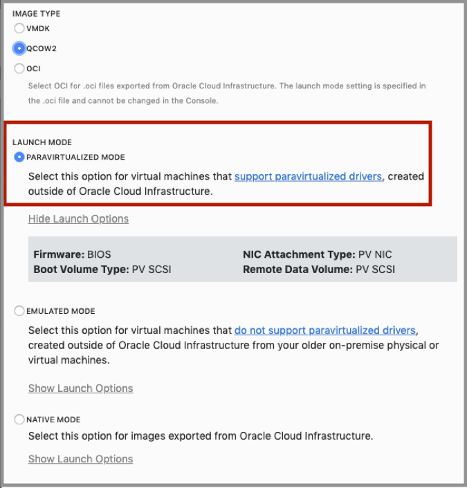
Click Import Image.
The import process starts. When the import is complete, the tile next to the image name changes from orange to green.
Deploy a BIG-IP VE instance
Deploy a BIG-IP VE instance from the custom image you created in the previous procedure. This instance is referred to as BIG-IP A.
Under the Compute section, click Instances.
Click Create Instance.
In the NAME box, enter a name, under Choose an operating system or image source, click Change Image Source, at the top click Custom Image, and select the image you created in the previous procedure, and then click Select Image.
Under the Availability Domain list, select the same availability domain you selected when creating your VCN subnets.
Under Instance Type, click Virtual Machine.
Under the Instance shape section click Change Shape, and select an appropriate shape based on your requirements. Shapes restrict the number of vCPUs, VNICs, and allocated memory.
Under Boot Volume section click the Custom boot volume size (in GB) and enter the volume size.
- BIG-IP VE Requirements: https://support.f5.com/csp/article/K14810
- Overview of the instance shapes within OCI
Click Show networking, under Configure Networking, expand the Subnet list and select Management.
If you want to access BIG-IP directly from the internet, click Show Advanced Options, click Networking, and then select the Assign Public IP Address checkbox.
Click Create.
When the instance is ready, the tile next to the instance name changes from orange to green.
Create three VNICs and reboot
When you created the instance, a primary VNIC was created automatically. This VNIC is for management traffic. You must create three more VNICs for the other subnet traffic.
Tip
Ensure the BIG-IP VE instance is running.
Under the Compute section, click Instances.
Click the name of your instance.
In the left menu, click Attached VNICs.
Click Create VNIC and complete the information for each VNIC:
Name Virtual Cloud Network Subnet Private IP address Assign public IP address External Your VCN External 10.0.1.2 Enable Internal Your VCN Internal 10.0.2.2 Disable HA Your VCN HA 10.0.3.2 Disable Click Create VNIC for each VNIC.
To reboot BIG-IP VE, click your instance, click Reboot, leave the default selection, and then click OK.
Important
You must reboot for BIG-IP VE to recognize the VNICs.
Create a secondary private IP for an External Floating Virtual IP
In the OCI console, create a secondary private IP on the external NIC.
- Click the top-left menu and under Compute, click Instances.
- Click the name of your instance.
- In the left menu, click Attached VNICs.
- Click the external VNIC.
- In the left menu, click IP Addresses, and then click Assign Private IP Address.
- For Private IP Address, in this example, type 10.0.1.201.
- If you want an external IP address for your application, select the Reserved Public IP option.
- Click Assign.
Create a secondary private IP for the external floating self-IP
In the OCI console, create a secondary private IP on the external NIC.
- Click the top-left menu and under Compute, click Instances.
- Click the name of your instance.
- In the left menu, click Attached VNICs.
- Click the external VNIC.
- In the left menu, click IP Addresses, and then click Assign Private IP Address.
- For Private IP Address, in this example, type 10.0.1.202.
- If you want an external IP address for your application, select the Reserved Public IP option.
- Click Assign.
Create a secondary private IP for the internal floating self-IP
In the OCI console, create a secondary private IP on the external NIC.
- Click the top-left menu and under Compute, click Instances.
- Click the name of your instance.
- In the left menu, click Attached VNICs.
- Click the internal VNIC.
- In the left menu, click IP Addresses, and then click Assign Private IP Address.
- For Private IP Address, in this example, type 10.0.2.202.
- Click Assign.
License BIG-IP VE
You must enter license information before you can use BIG-IP VE.
Open a web browser and log in to the BIG-IP Configuration utility by using https with your Primary VNIC’s public IP Address, for example: https: <external-ip-address>. The username is root and password is default.
On the Setup Utility Welcome page, click Next.
On the General Properties page, click Activate.
In the Base Registration key field, enter the case-sensitive registration key from F5.
For Activation Method, if you have a production or Eval license, choose Automatic and click Next. If you chose Manual, do the following:
In the Step 1: Dossier field, copy all of the text, and then Click here to access F5 Licensing Server.
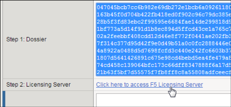
A separate web page opens.
On the new page, click Activate License.
In the Enter your dossier field, paste the text, and then click Next.
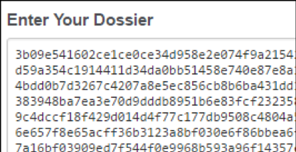
Accept the agreement and click Continue.
On the Activate F5 Product page, copy the license text in the box. Return to the BIG-IP Configuration utility and paste the text into the Step 3: License field.
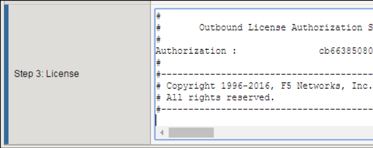
Click Next.
The BIG-IP VE system registers the license and logs you out. When the configuration change is successful, click Continue to provision BIG-IP VE.
Provision BIG-IP VE
You must confirm the modules you want to run, before you can begin to work in the BIG-IP Configuration utility.
Open a Web browser and log in to the BIG-IP Configuration utility.
On the Resource Provisioning screen, change settings if necessary, and then click Next.
On the Device Certificates screen, click Next.
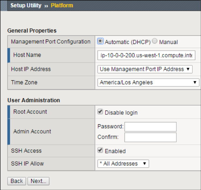
On the Platform screen, in the Admin Account text box, re-enter the password for the admin account, and then click Next.
BIG-IP VE logs you out.
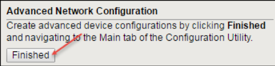
When you log back in, on the screen, in the Advanced Network Configuration section, click Finished.
Create VLANs
In BIG-IP VE, you must create an external and internal VLAN that corresponds to the Oracle subnets.
- In the BIG-IP VE Configuration utility, on the Setup Utility Network page, under Advanced Network Configuration, click Finished.
- On the Main tab, click .
- Click Create and complete the following information for the external VLAN:
- Name–External
- Interface–1.1
- Tagging–Untagged
- Click Finished.
- Click Create again, and complete the following information for the internal VLAN.
- Name–Internal
- Interface–1.2
- Tagging–Untagged
- Click Finished.
- Click Create and complete the following information for the HA VLAN.
- Name–HA
- Interface–1.3
- Tagging–Untagged
- Click Finished.
Create self-IPs
Before using the BIG-IP VE Configuration utility tool, in the OCI interface record the primary private IP addresses for the following interfaces:
- external
- internal
- HA network
In the OCI interface, record the secondary IP addresses for the following network interfaces:
- external
- internal network
In BIG-IP VE Configuration utility tool, to create a self IP address, based on these private IP addresses, on the Main tab, click .
Click Create and complete the following information for the external self IP address.
- Name–ExternalSelfIP
- IP Address–10.0.1.2
- Netmask–255.255.255.0
- VLAN/Tunnel–external
- Port Lockdown–Allow None
Click Repeat and complete the following information for the internal self IP address.
- Name–InternalSelfIP
- IP Address–10.0.2.2
- Netmask–255.255.255.0
- VLAN/Tunnel–internal
- Port Lockdown–Allow None
Click Repeat and complete the following information for the HA self IP address.
- Name–HASelfIP
- IP Address–10.0.3.2
- Netmask–255.255.255.0
- VLAN/Tunnel–HA
- Port Lockdown–Allow All
Click Create and complete the following information for the external floating self IP address.
- Name–ExternalFloatingSelfIP
- IP Address–10.0.1.202
- Netmask–255.255.255.0
- VLAN/Tunnel–external
- Port Lockdown–Allow None
Click Repeat and complete the following information for the internal floating self IP address.
- Name–InternalFloatingSelfIP
- IP Address–10.0.2.202
- Netmask–255.255.255.0
- VLAN/Tunnel–internal
- Port Lockdown–Allow None
Click Finished.
The screen refreshes, and the five new self IP addresses appear in the list.
Create a route entry on the BIG-IP for Internet & Internal Networks
Before doing the following procedure, in OCI, record the first IP addresses for the external and internal subnets. Then, in BIG-IP VE, create network route entries, based on these IP addresses.
Important
You may not need routes or may need only a default route to the Internet. Consider how you want to access the pool members. If all members are on the Internal subnet, then no Internal network route is required.
Using the BIG-IP VE Configuration utility tool, on the Main tab, click .
Click Create and complete the following information for the default route out to the internet.
- Name–DefaultRoute
- Destination–0.0.0.0
- Netmask–0.0.0.0
- Gateway Address–10.0.1.1
Click Repeat and complete the following information for any internal networks as needed.
- Name–InternalNetworkRoute
- Destination–10.0.0.0
- Netmask–255.255.0.0
- Gateway Address–10.0.2.1
Click Finished.
The screen refreshes, and the new routes appear in the list.
Create a management route entry on the BIG-IP for OCI networks
Before starting these steps, in OCI, record the first IP addresses for the management subnet. Then in BIG-IP VE, create management network route entries, based on these IP addresses. You must SSH into the BIG-IP VE, and use TMSH commands to apply management routes. This ensures that connectivity to OCI endpoints on 169.254.0.0/16 flow out the management address.
SSH into the BIG-IP VE as root user.
If you are at a tmos/tmsh prompt, continue to Step 3; otherwise, type
tmsh.Type the following command to enable routing for RFC3927 IP addresses used by OCI:
modify sys db config.allow.rfc3927 { value enable }Add a management route to route RFC3927 addresses used by OCI out of the management network:
create sys management-route oci-169.254.0.0_16 { network 169.254.0.0/16 gateway 10.0.0.1 }To save the configuration, type:
save sys config.
Create a pool and add members to the pool
Traffic goes through BIG-IP VE to a pool. Your application servers must be members of this pool.
- Open a web browser and go to the BIG-IP Configuration utility, using the public IP address on the management network,
for example:
https <external-ip-address>. - On the Main tab, click .
- Click Create.
- In the Name text box, type
web pool. Names must begin with a letter, be fewer than 63 characters, and can contain only letters, numbers, and the underscore (_) character. - For Health Monitors, move https from the Available to the Active list.
- Choose the load balancing method or retain the default setting.
- In the New Members section, in the Address text box, type the IP address of the application server.
- In the Service Port text box, type a service port; for example, 443.
- Click Add. The member appears in the list.
- Add more pool members as needed, and then click Finished.
Create a virtual server
You must create a virtual server for the secondary private IP address that’s associated with the external network interface. Application traffic goes to the Elastic IP (EIP) address associated with this BIG-IP VE virtual server.
In the BIG-IP Configuration utility, on the Main tab, click .
Click Create and complete the following information:
- Name–A unique name.
- Destination Address/Mask–10.0.1.201 (A secondary private IP address on the external NIC).
- Service Port–A port number or a service name from the Service Port list.
- HTTP Profile–http.
- Source Address Translation–Auto Map.
- Default Pool–web_pool.
Configure any other settings as needed, and then click Finished.
Traffic to the virtual server IP address will now go to the pool members.
Deploy BIG-IP B
The second instance of BIG-IP VE is referred to as BIG-IP B.
Create a second BIG-IP VE
Now deploy a second BIG-IP VE instance from the custom image you created. Follow the same instructions as the first BIG-IP A.
Call this instance BIG-IP B and the first instance BIG-IP A.
Create VNICs and reboot
You must associate three VNICs with BIG-IP B.
Important
Ensure the BIG-IP VE instance is running.
In the OCI console, under the Compute section, click Instances.
Click the name of your instance (BIG-IP B).
In the left menu, click Attached VNICs.
Click Create VNIC and complete the fields one time for each VNIC:
Name Virtual Cloud Network Subnet Private IP address Assign public IP address External Your VCN External 10.0.1.3 Enable Internal Your VCN Internal 10.0.2.3 Disable HA Your VCN HA 10.0.3.3 Disable Click Create VNIC.
To reboot BIG-IP VE, click the instance name, click Reboot, leave the default selection, and then click OK.
Important
You must reboot for BIG-IP VE to recognize the VNICs.
Create three VLANs on BIG-IP B
In BIG-IP B, you must create an external and internal VLAN that corresponds to the Oracle subnets.
Create three self IP addresses
Click Create and complete the following information for the external self IP address.
- Name–ExternalSelfIP
- IP Address–10.0.1.3
- Netmask–255.255.255.0
- VLAN/Tunnel–external
- Port Lockdown–Allow All
Click Repeat and complete the following information for the internal self IP address.
- Name–InternalSelfIP
- IP Address–10.0.2.3
- Netmask–255.255.255.0
- VLAN/Tunnel–internal
- Port Lockdown–Allow All
Click Repeat and complete the following information for the HA self IP address.
- Name–HASelfIP
- IP Address–10.0.3.3
- Netmask–255.255.255.0
- VLAN/Tunnel–HA
- Port Lockdown–Allow All
Click Finished.
The screen will refresh, displaying three new self IP addresses in the list.
Create a management route entry on the BIG-IP for OCI Networks
Before starting these steps, in OCI, record the first IP addresses for the management subnet. Then in BIG-IP VE, create management network route entries, based on these IP addresses. You must SSH into the BIG-IP VE, and use TMSH commands to apply management routes. This ensures that connectivity to OCI endpoints on 169.254.0.0/16 flow out the management address.
SSH into the BIG-IP VE as root user.
If you are at a tmos/tmsh prompt, continue to Step 3; otherwise, type
tmshType the following command to enable routing for RFC3927 IP addresses used by OCI:
modify sys db config.allow.rfc3927 { value enable }Add a management route to route RFC3927 addresses used by OCI out the management network:
create sys management-route oci-169.254.0.0_16 { network 169.254.0.0/16 gateway 10.0.0.1 }Save the configuration:
save sys config
Configure High Availability
You must first configure BIG-IP A and B to communicate for the purposes of synchronizing their configurations and failing over.
However, HA will not work until the final step, where you configure scripts to reassign the secondary private IP address (the virtual IP, or VIP and Floating SelfIPs). These steps are detailed in the final section of the guide.
Specify config sync, failover, and mirroring addresses
Each BIG-IP VE needs to synchronize its configuration with and assess the health of the other BIG-IP VE.
- Log in to the BIG-IP Configuration utility on BIG-IP A.
- On the Main tab, click .
- In the Name column, click BIG-IP A.
- From the Device Connectivity menu, choose ConfigSync.
- For the Local Address setting, select the static self IP address for BIG-IP A’s internal VLAN, 10.0.2.2, and then click Update.
- From the Device Connectivity menu, choose Failover Network.
- For the Failover Unicast Configuration settings, click Add and specify the static self IP address for BIG-IP A’s HA VLAN, 10.0.3.2.
- Click Finished.
Now log in to BIG-IP B, and do the following:
On the Main tab, click .
In the Name column, click BIG-IP B.
From the Device Connectivity menu, choose ConfigSync.
For the Local Address setting, select the static self IP address for BIG-IP B’s internal VLAN, 10.0.2.3, and click Update.
From the Device Connectivity menu, choose Failover Network.
For the Failover Unicast Configuration settings, click Add and specify the static self IP address for BIG-IP B’s HA VLAN, 10.0.3.3.
Click Finished.
Now each BIG-IP VE can use the IP addresses of the other BIG-IP VE to sync its configuration and fail over.
Establish trust between the BIG-IP VEs
Before joining a Sync-Failover device group, both BIG-IP VEs must authenticate each others’ certificates to create trust.
Note
Do this task on BIG-IP A ONLY.
Log in to the BIG-IP Configuration utility on BIG-IP A.
On the Main tab, click , and then select Device Trust Members.
Click Add.
For the IP address, type the management address for BIG-IP B, 10.0.0.3.
This is the primary private IP address associated with BIG-IP B’s management subnet.
Type the administrative user name and password.
Click Retrieve Device Information.
BIG-IP A discovers BIG-IP B and displays information about it. Confirm that BIG-IP B’s certificate is correct and click Device Certificate Matches.
Confirm that BIG-IP B’s certificate is correct.
Confirm that the management IP address and name of BIG-IP B are correct.
Click Device Certificate Matches.
Confirm the name and click Add Device.
BIG-IP A and BIG-IP B now trust each other. In the top left, the status changes to In Sync.
Create a Sync-Failover device group
You must put the two BIG-IP-IP VEs into a Sync-Failover device group. If an active BIG-IP VE in the Sync-Failover device group becomes unavailable, its configuration objects fail over to the other BIG-IP VE and traffic processing resumes.
Note
Do this task on BIG-IP A only.
Log in to the BIG-IP Configuration utility on BIG-IP A.
On the Main tab, click .
On the Device Groups list screen, click Create.
Type a name for the device group, like bigip_ve_oracle.
Select the device group type, Sync-Failover.
In the Configuration pane, select both BIG-IP VEs from the Available list, and then click Move.
Both BIG-IP VEs appear in the Includes list.
For the Sync Type, leave Manual with Incremental Sync.
Click Finished.
You now have a sync-failover device group that contains both BIG-IP VEs.
Sync the BIG-IP configuration to the device group
You must synchronize the BIG-IP configuration data from BIG-IP A to BIG-IP B. This data includes the floating virtual IP address, 10.0.1.202.
Note
Do this task on BIG-IP A ONLY.
Log in to the BIG-IP Configuration utility on BIG-IP A.
On the Main tab, click .
In the Device Groups pane, from the Name column, select the device group you created earlier, such as bigip_ve_oracle.
The screen expands to show a summary and details of the sync status of the device group, as well as a list of the two BIG-IP VEs within the device group.
In the Devices pane, in the Sync Status column, select the device that shows a sync status of Changes Pending (or Awaiting Initial Sync).
Click Sync.
This syncs the most recent changes on BIG-IP A to the other member of bigip_ve_oracle, BIG-IP B. In the top left, one BIG-IP should show Active status, and the other, Standby.
If you have issues with high availability, check the log messages by using SSH to log in to the BIG-IP VEs.
At the system prompt, type the command tail -n 20 /var/log/ltm. This shows the most recent twenty rows of log messages.
Finalize High Availability
Finally, you must customize and deploy scripts that allow BIG-IP VE to communicate with Oracle and move the virtual IP address from one BIG-IP VE to the other.
Create API keys
You need keys for BIG-IP to interact with the Oracle API. You will create the keys locally, and then copy the public key into the OCI console.
Generate public and private keys, and then complete the Generate an API Signing Key task.
When done, you will have two files in a folder named, oci_:
- oci_api_key.pem
- oci_api_key_public.pem
To add the contents of the .pem file to OCI, open the OCI console, and in the top-right corner, next to your username, hover over the down-arrow and click User Settings.
In the API Keys section, click Add Public Key, paste the contents of
oci_api_key_public.pemfile into the box, and then click Add.A Fingerprint is generated.
Copy files from GitHub
Now you are going to copy some files from github, edit them, and then copy the files to the BIG-IP VE instances.
Note
Although F5 supports BIG-IP VE in OCI, these High Availability files on GitHub are community-supported.
Copy the following files from github (https://github.com/f5devcentral/f5-oci-failover) to a local directory where you can edit them.
tgactiveoci-curlvnicext2.jsonvnicint2.json
You will edit these files, and then copy them to the BIG-IP VE instances.
Alternately, you can copy them to BIG-IP VE now and edit while on the instance. See Copy the files to BIG-IP VE instances topic for more information on where to copy the files.
Edit the oci-curl file
You must edit the oci-curl file to have information about your OCI environment.
Important
When editing these files, be sure your editor is using UNIX style line terminations (LF) and not Windows style line terminations (CRLF). If you do edit in Windows, you can use the dos2unix utility to fix the line endings in the file.
Specifically, you need values for the following four settings:
local tenancyId="ocid1.tenancy.oc1..ocid1.privateip.oc1.phx.abyhqljREPLACETHISWITHYOUROCIDSa";``
local authUserId="ocid1.user.oc1..aaaaaaaaky3iyt7oqbdolpppdnqfbbarbREPLACETHISWITHYOUROCIDSvwq";``
local keyFingerprint="b0:77:5f:39:37:36:e2:dc:98:d2:00:00:00:00:00:00";``
local privateKeyPath="/config/failover/oci_api_key.pem";``
To get the tenancyId
- In the OCI console, at the top of the page, click the tenancy name.
- Under Tenancy Information, next to OCID, click Show.
- Copy the value and paste it into the
oci-curlfile as the tenancyID value.
To get the authUserId
- In the OCI console, in the top-right corner, next to your username, hover over the down arrow and click User Settings.
- In the User Information section, next to OCID, click Show.
- Copy the value and paste it into the
oci-curlfile as the authUserId value.
To get the keyFingerprint
- In the top-right corner, next to your username, hover your mouse over the down arrow and click User Settings.
- In the left menu, click API Keys.
- In the API Keys section, copy the fingerprint and paste it into the
oci-curlfile as the keyFingerprint value.
To get the privateKeyPath
Connect to the BIG-IP VE instance and copy your .pem file into the config/failover folder.
If you used a .pem file other than the one generated by following the Oracle documentation, you may need to update the privatekeypath value.
Edit the active file
Open the active file and replace these values.
Replace the region URL
Replace the region URL with the one specific to your region.
Go to Oracle API.
In the section called Core Services API (covering Networking, Compute, and Block Volume), find the region in which you are working; for example:
iaas.us-phoenix-1.oraclecloud.com.In the active file, in the following text replace where indicated with this value:
# External Secondary Self-IP failover
/config/failover/oci-curl iaas.us-phoenix-1.oraclecloud.com PUT /config/OCI/vnicext2.json "/20160918/privateIps/ocid1.privateip.oc1.phx.abyhqljREPLACETHISWITHYOUROCIDShdy"

# External Secondary VIP failover
/config/failover/oci-curl iaas.us-phoenix-1.oraclecloud.com PUT /config/OCI/vnicext2.json "/20160918/privateIps/ocid1.privateip.oc1.phx.abyhqljREPLACETHISWITHYOUROCIDSABC"

# Internal Secondary Self-IP failover
/config/failover/oci-curl iaas.us-phoenix-1.oraclecloud.com PUT /config/OCI/vnicint2.json "/20160918/privateIps/ocid1.privateip.oc1.phx.abyhqljREPLACETHISWITHYOUROCIDSZYA"
Replace the OCID for the secondary external private IP address
Find the OCID of the secondary private IP address on the external VNIC:
Open OCI console, click the Main menu and under Compute, click Instances.
Click the name of your instance.
In the left menu, click Attached VNICs.
Click the name of the external VNIC.
Look at the secondary private IP address, 10.0.1.202 in this example.
Next to the Private IP OCID, click Show, and then copy the Private IP OCID value.
In the active file, in the following text replace where indicated with the following value:
# External Secondary IP fail over
/config/failover/oci-curl iaas.us-phoenix-1.oraclecloud.com PUT /config/OCI/vnicext2.json "/20160918/privateIps/ocid1.privateip.oc1.phx.abyhqljREPLACETHISWITHYOUROCIDShdy"
Delete the following section of the file:
# Internal Secondary IP failover
/config/failover/oci-curl console.us-phoenix-1.oraclecloud.com PUT /config/OCI/vnicint2.json "/20160918/privateIps/ocid1.privateip.oc1.phx.abyhqljREPLACETHISWITHYOUROCIDS5dq"
Ensure that the path to json files is correct
Ensure that the path to the json file is /config/failover. In the default script, the value is /config/OCI/vnicint2.json.
It must be /config/failover, because that is the location where you will copy the files.
Edit the json files
Update the json files with the OCID values of the VNICs.
Create a copy of the
vnicint2.jsonandvnicext2.jsonfiles. One copy will go on BIG-IP A, and one on BIG-IP B.Edit vnicint2.json and vnicext2.json files, according to the BIG-IP VE to which it applies.
BIG-IP 1:
vnicint2.json
          OCID of Internal VNIC of BIG-IP 1
vnicext2.json
          OCID of External VNIC of BIG-IP 1
BIG-IP 2:
vnicint2.json
          OCID of Internal VNIC of BIG-IP 2
vnicext2.json
          OCID of External VNIC of BIG-IP 2
To find these OCIDs
- Open OCI console, click the Main menu, and under Compute, click Instances.
- Click the name of the instance.
- In the left menu, click Attached VNICs.
- Click the name of the VNIC, and then click Copy next to the OCID.
Copy the files to BIG-IP VE instances
Connect to BIG-IP A and copy the
tgactiveandoci-curlfiles to the/config/failoverfolder.Tip
- These two files must be the same on both BIG-IP VE instances.
- You are overwriting an existing file named, tgactive. If you want to preserve it, then rename it to tgactive_old.
Connect to BIG-IP B and copy the tgactive and oci-curl files to the
/config/failoverfolder.Copy the two .json files to each BIG-IP VE instance. These files are specific to each BIG-IP VE.
On each BIG-IP VE, set permissions on the
tgactiveandoci-curlfiles so they have execute permissions:chmod +x /config/failover/oci-curl chmod +x /config/failover/tgactive
On each BIG-IP VE, Modify the
failover.selinuxallowscripts sys dbto allow the failover scripts to run:tmsh modify sys db failover.selinuxallowscripts value enable tmsh save sys config
On each BIG-IP VE, copy the .pem file from your local .oci folder:
- Previously, you created a .pem file called oci_api_key.pem. Copy this .pem file into the
/config/failoverfolder. - If you used a .pem file other than the one generated by the following the Oracle documentation, or your .pem file has a different name, open the oci-curl file and ensure the privatekeypath reflects the location and name of your file.
- Previously, you created a .pem file called oci_api_key.pem. Copy this .pem file into the
Trigger fail over
Do the following to trigger the fail over:
- On the active BIG-IP VE instance, log into the Configuration utility.
- Under , select the check box by traffic-group-1, and then click Force to Standby.
- In the OCI console, observe the secondary private IP address on the external VNIC move from the standby BIG-IP VE instance to the active instance.
Tip
To create fail over objects for more than two interfaces:
Add a line to the
tgactivescript for that VNIC.Add a
jsonfile for the objects to which you want to fail over.Consult the https://github.com/f5devcentral/f5-oci-failover repository.
Troubleshooting fail over
Do the following to troubleshoot the fail over.
On both BIG-IP VE instances, SSH into the CLI.
Check the
failover.selinuxallowscriptsdb variable and confirm it is enabled.tmsh list sys db failover.selinuxallowscriptsAttempt to run the fail over scripts manually.
bash /config/failover/tgactiveReview output from running the script and check if the secondary IPs moved to the BIG-IP on which you ran the script.
BIG-IP in OCI performance note
In cases where high CPU performance is required, the default method BIG-IP uses to pin TMM threads to cores is non-optimal for OCI compute instances. By default, TMM threads are pinned to the first logically numbered cores in sequence, this normally assigns a one-TMM instance per core. However, OCI uses an atypical logical CPU layout that causes this strategy to assign two TMM threads per core. This results in 30% less performance than normally expected.
F5 has developed a solution to achieve optimal performance within OCI. There is an Engineering Hot Fix (EHF) that you can apply
in conjunction with a sys db variable that modifies the way TMM is pinned to CPU cores to accommodate OCI’s atypical
processor layout.
Request EHF for BZID 1178225 from F5 Support.
Install EHF using normal EHF installation instructions: K55025573: Engineering hotfix installation overview
Once you install the EHF rebooted into the new version, using the CLI, enable the following
sys db, and use the list command to verify:tmsh modify sys db ve.scheduler.cputhreaded value true tmsh list sys db ve.scheduler.cputhreaded tmsh save sys config
Restart TMM. This will affect traffic.
tmsh restart sys service tmmVerify the new TMM pinning. The second column shows on which CPU process is running. Notice the alternating CPU IDs 0,2,4,6, and so forth:
[admin@oci-bigip-0:Active:Disconnected] ~ # ps -T -e -o pid,psr,pcpu,cmd | grep -E "tmm.0"
18649   0  8.3 tmm.0 -T 8 --tmid 0 --npus 8 --platform Z100 -m -s 33288
18649   2  8.3 tmm.0 -T 8 --tmid 0 --npus 8 --platform Z100 -m -s 33288
18649   4  8.3 tmm.0 -T 8 --tmid 0 --npus 8 --platform Z100 -m -s 33288
18649   6  7.9 tmm.0 -T 8 --tmid 0 --npus 8 --platform Z100 -m -s 33288
18649   8  8.1 tmm.0 -T 8 --tmid 0 --npus 8 --platform Z100 -m -s 33288
18649  10  8.0 tmm.0 -T 8 --tmid 0 --npus 8 --platform Z100 -m -s 33288
18649  12  8.4 tmm.0 -T 8 --tmid 0 --npus 8 --platform Z100 -m -s 33288
18649  14  9.1 tmm.0 -T 8 --tmid 0 --npus 8 --platform Z100 -m -s 33288