F5 VE SmartNIC Routing Reference Guide
The reference guide details F5® BIG-IP VE® SmartNIC N3000 FPGA routing for the following specific port configurations and optic mode configurations.
FPGA VLAN routing
The following section discusses SR-IOV virtual functions, 1-port, and 2-port configurations.
Mapping SR-IOV virtual functions to the BIG-IP VE interface
SR-IOV virtual functions (VFs) are BIG-IP VE interfaces that are NOT directly mapped to a physical MAC address (MAC PORT) on a physical port. Instead, mapping between VFs and physical ports are derived based on VLAN. There is a VLAN to MAC PORT learning table constantly updating based on which MAC PORT a VLAN tagged packet was last received.
Ingress VLAN tagged packets are routed to the VF with the corresponding VLAN and VF_MAC_ADDR assigned regardless of what MAC PORT the packet arrived. Any packet that does NOT match the VLAN and VF_MAC_ADDR of a VF is dropped inside the FPGA.
Egress packets from BIG-IP VE interfaces use the VLAN PORT Table inside the FPGA to determine the port on which to send out the packet. The only exception is if Trunk Mode is enabled using the F5 SmartNIC Orchestrator on the hypervisor. In this case, the egress port is selected by a hash on the packet tuple.
Important
- In order to offload both sides of the connection (pva-acceleration) in the FPGA, both client and server VLANs MUST reside on the same BIG-IP VE interface.
- VE trunks with multiple interfaces (VFs) are NOT supported.
- A VE trunk assigned with only one interface and N number of VLANs is supported.
1-port configuration
The following diagram describes FPGA packet routing with one port:
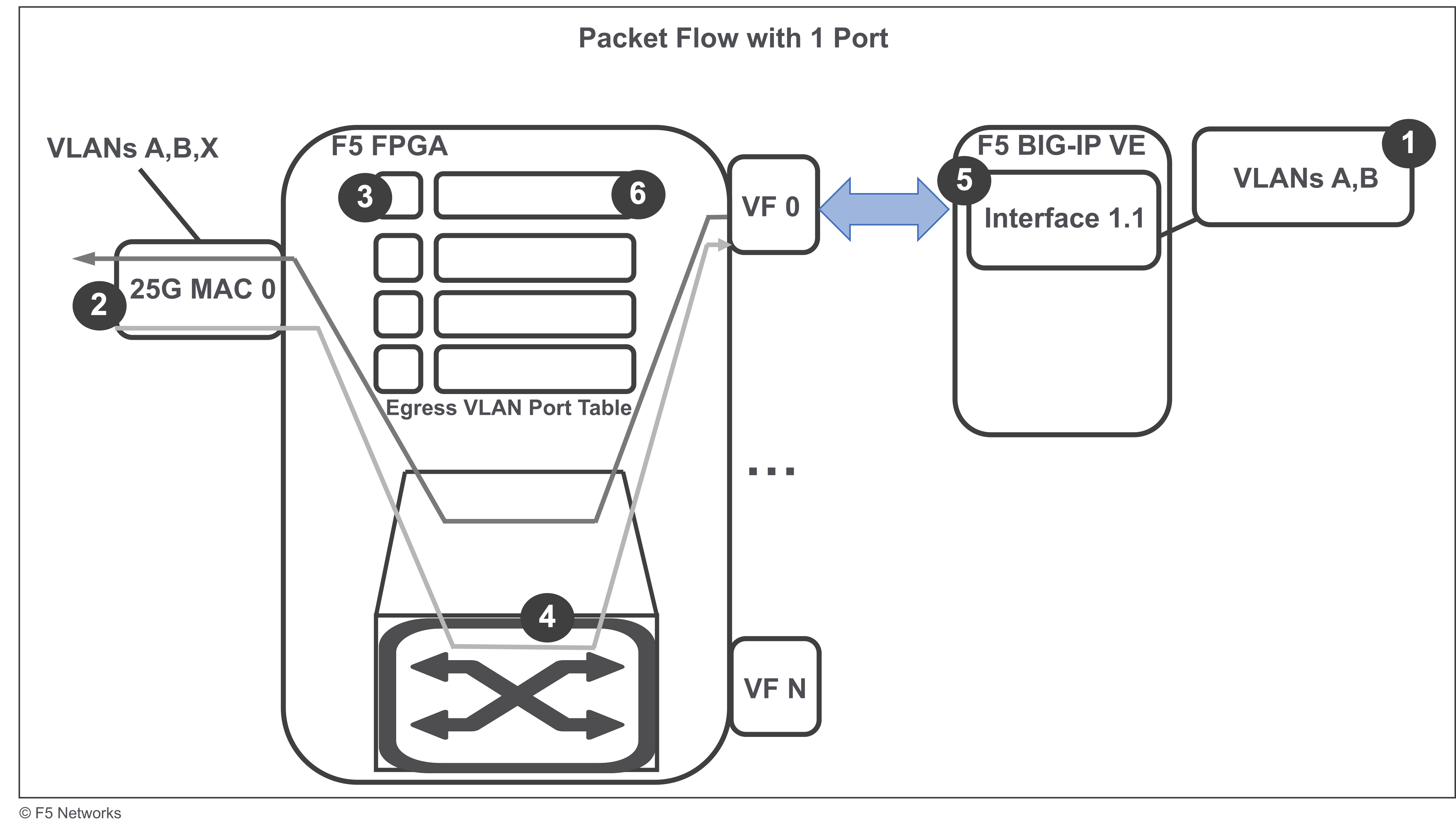
- VLANs A,B are assigned to interface 1.1 in BIG-IP VE.
- A tagged packet with VLAN A and VF_MAC_ADDR matching interface 1.1 (VF 0) arrives at MAC PORT 0.
- Egress VLAN Port Table updates VLAN A’s entry to associate it with MAC PORT 0.
- FPGA determines that the packet is destined for interface 1.1 based on VF_MAC_ADDR and VLAN.
- BIG-IP VE receives the packet and responds with another tagged packet with VLAN A.
- FPGA looks up the egress packet in the VLAN Port Table, and maps VLAN A to MAC PORT 0.
2-port configuration
The following diagram describes FPGA packet routing with two ports:
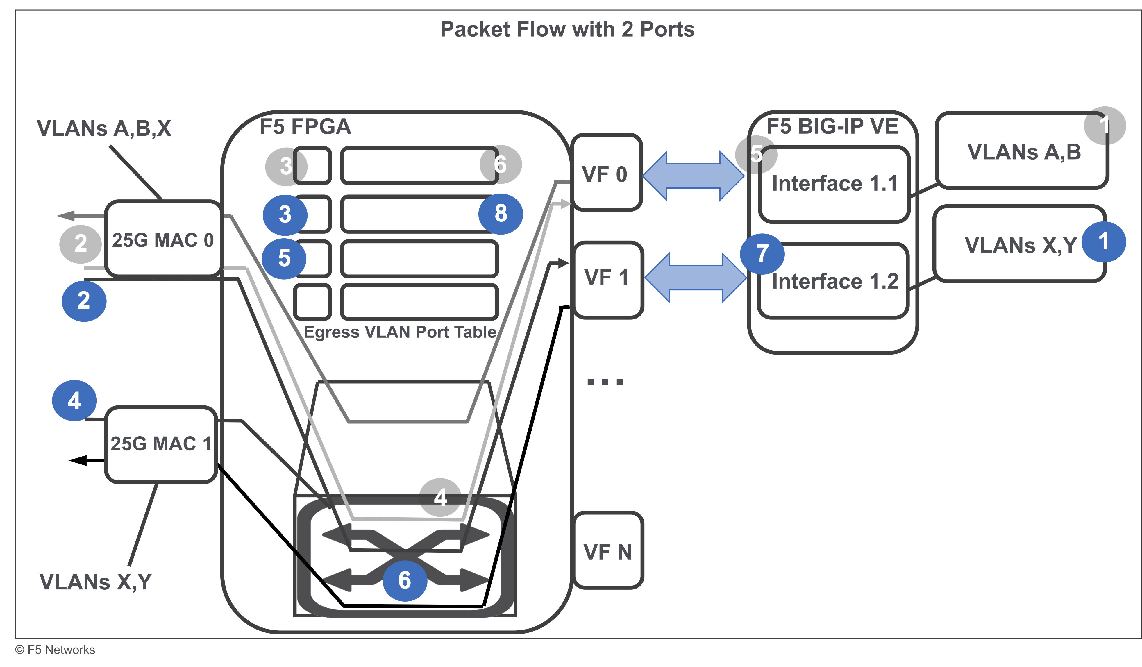
- VLANs X,Y are assigned interface 1.2 in BIG-IP VE.
- A tagged packet with VLAN X and VF_MAC_ADDR matching interface 1.2 (VF 1) arrives at MAC PORT 0.
- Egress VLAN Port Table updates VLAN X’s entry to associate it with MAC PORT 0.
- Another tagged packet with VLAN Y and VF_MAC_ADDR matching interface 1.2 (VF 1) arrives at MAC PORT 1.
- Egress VLAN Port Table updates VLAN Y’s entry to associate it with MAC PORT 1.
- FPGA determines that both packets are destined for interface 1.2 based on the VF_MAC_ADDR and VLANs.
- BIG-IP VE receives both packets and only responds with a single tagged packet with VLAN Y.
- FPGA looks up the egress packet in the VLAN Port Table, and maps VLAN Y to MAC PORT 1.
F5 SmartNIC deployment topologies
Review SmartNIC FPGA routing for the following 1-optic and 2-optic topologies:
1-optic mode
One optic mode has the following options:
- Standard mode without redundancy
- Trunk mode without redundancy
- Standard mode with active/active redundancy
- Standard mode with active/standby redundancy
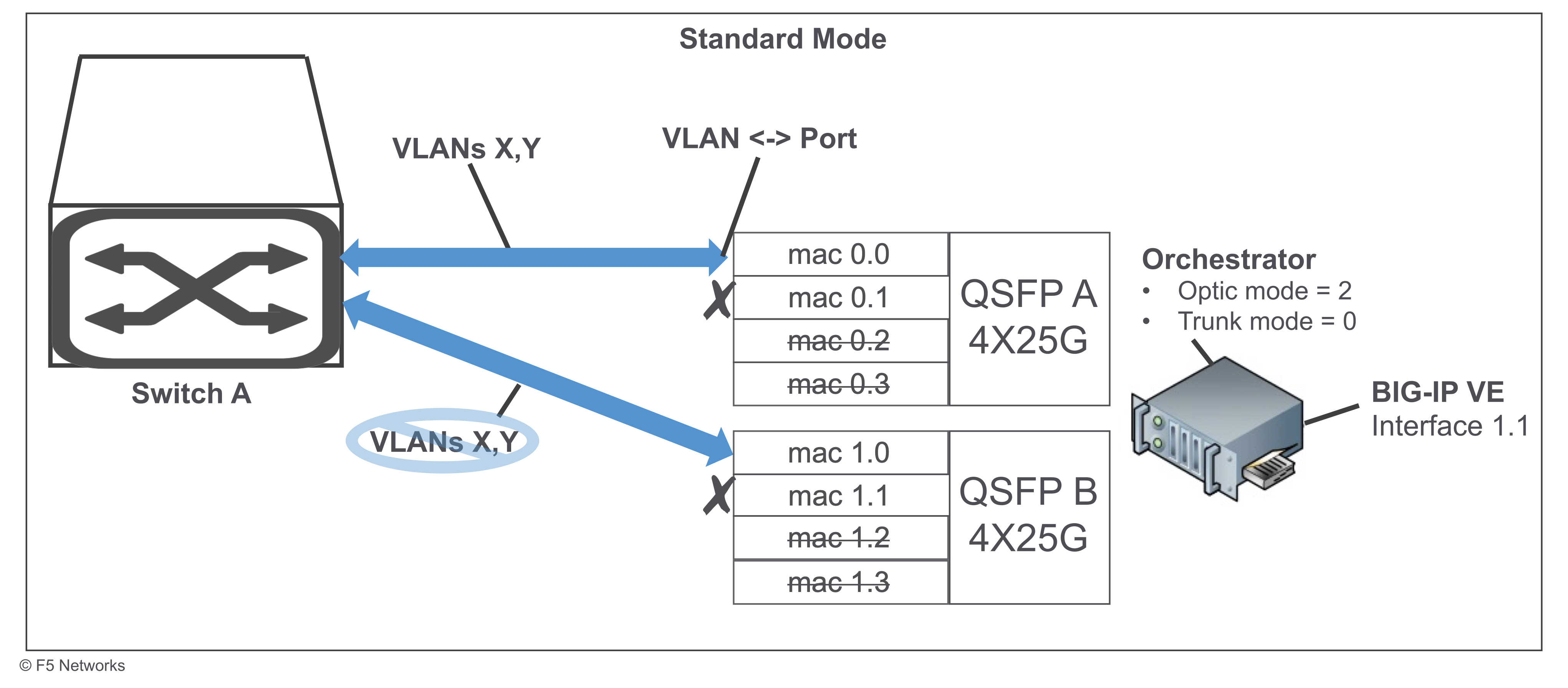
Standard mode for 1-optic
The following diagram describes the standard mode configuration with:
- A maximum throughput of 25G
- No redundancy
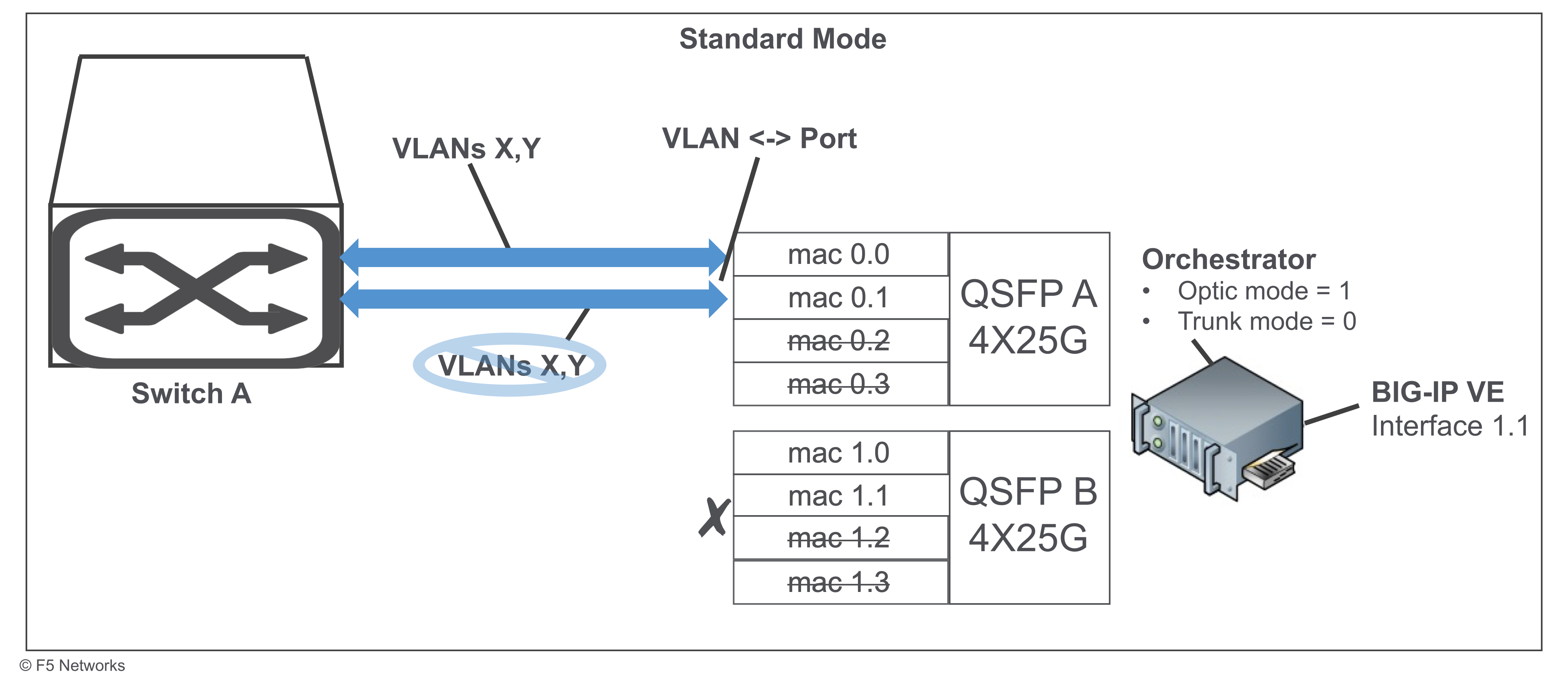
- VLAN <-> port - mapping is learned in the hardware and determines the egress MAC Port assignment.
- BIG-IP VE interface 1.1 - is the virtual function of the primary physical function for VLANs X,Y.
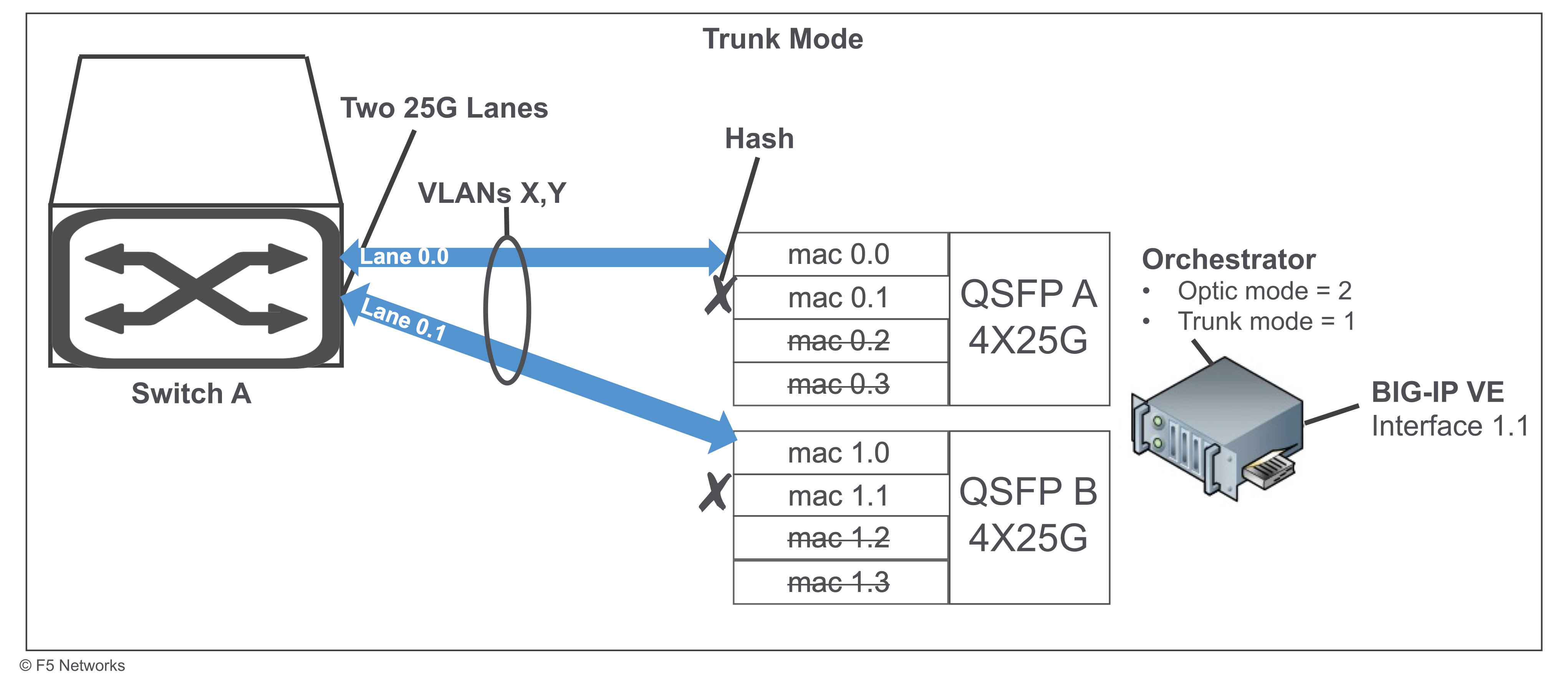
Trunk mode for 1-optic
The following diagram describes the trunk mode configuration with:
- A maximum throughput of 50G
- No redundancy
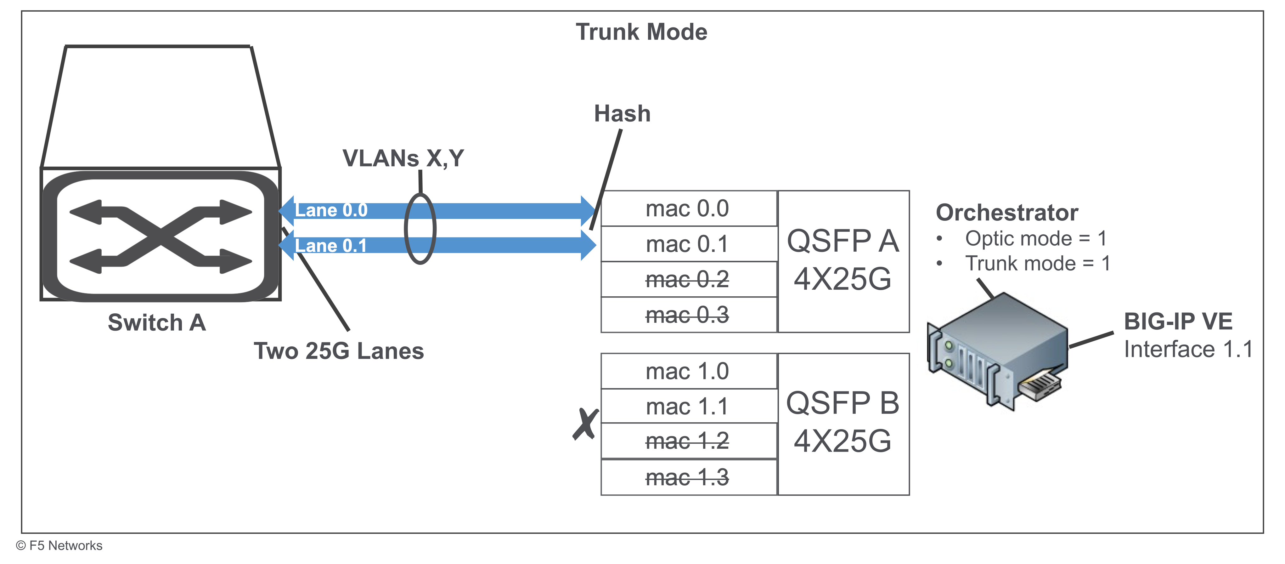
- 25G lanes - use the switch to aggregate lanes 0.0 and 0.1.
- Hash determines the egress MAC Port.
- BIG-IP VE interface 1.1 - is the virtual function of the primary physical function for VLANs X,Y.
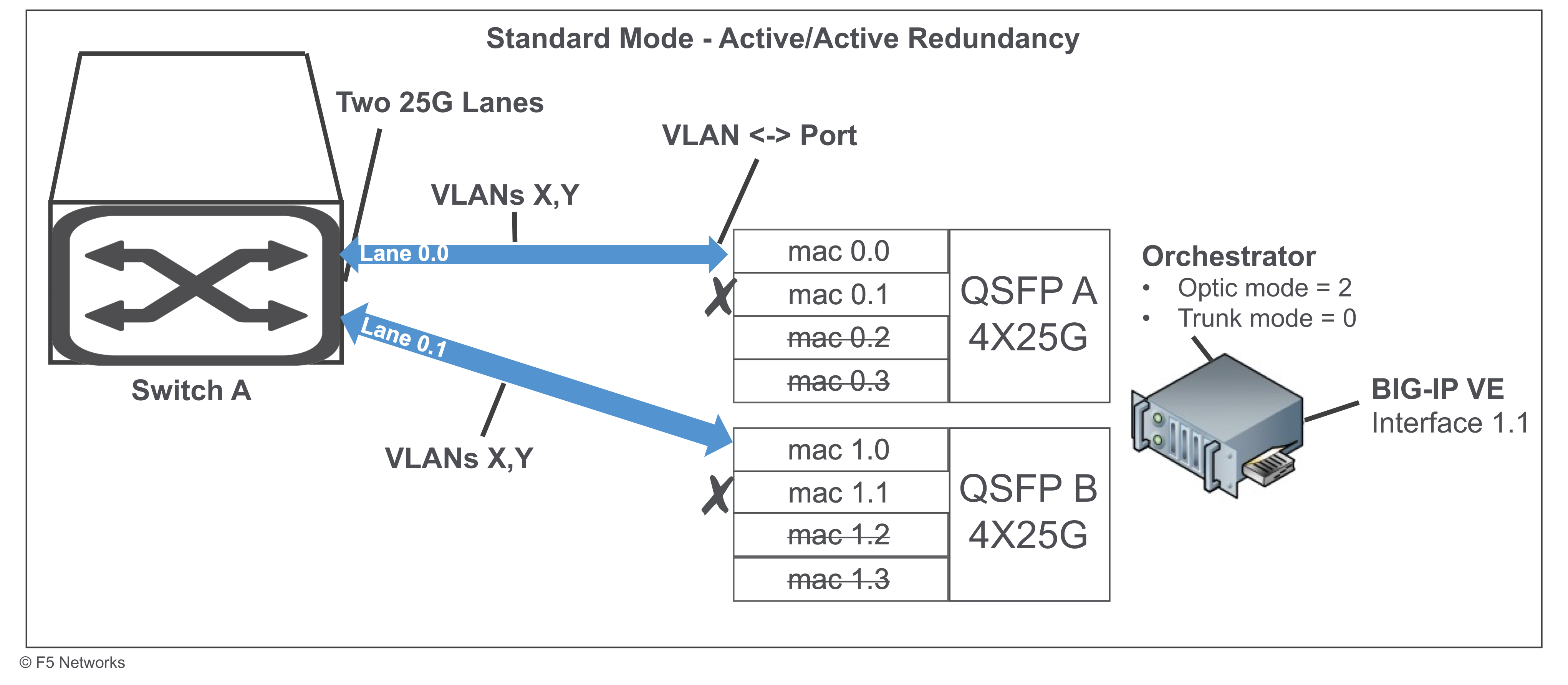
Standard mode active/active redundancy for 1-optic
The following diagram describes the standard mode active/active redundancy configuration with:
- A maximum throughput of 25G+
- Active/Active Redundancy
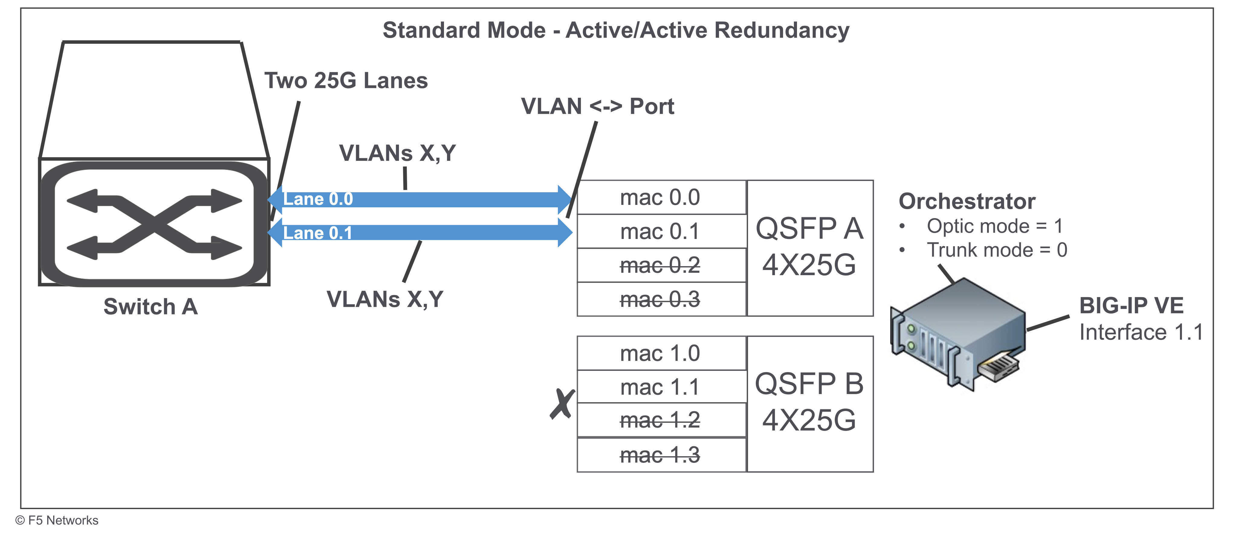
VLAN <-> port - mapping is learned in the hardware and determines the egress MAC Port assignment.
25G lanes - OPTIONAL you can use the switch to aggregate lanes 0.0 and 0.1 to share same VLANs.
BIG-IP VE interface 1.1 - is the virtual function of the primary physical function for VLANs X,Y.
Important
- If 25G lanes 0.0 or 0.1 are up and active and the switch is sending traffic down each lane based on a hash, then the FPGA is constantly switching the egress port for a particular VLAN.
- If one 25G lanes 0.0 or 0.1 is down, then the switch only sends traffic to the lane that is up. The FPGA learns the appropriate egress port of where active traffic is, so you can maintain at least 25G of connectivity.
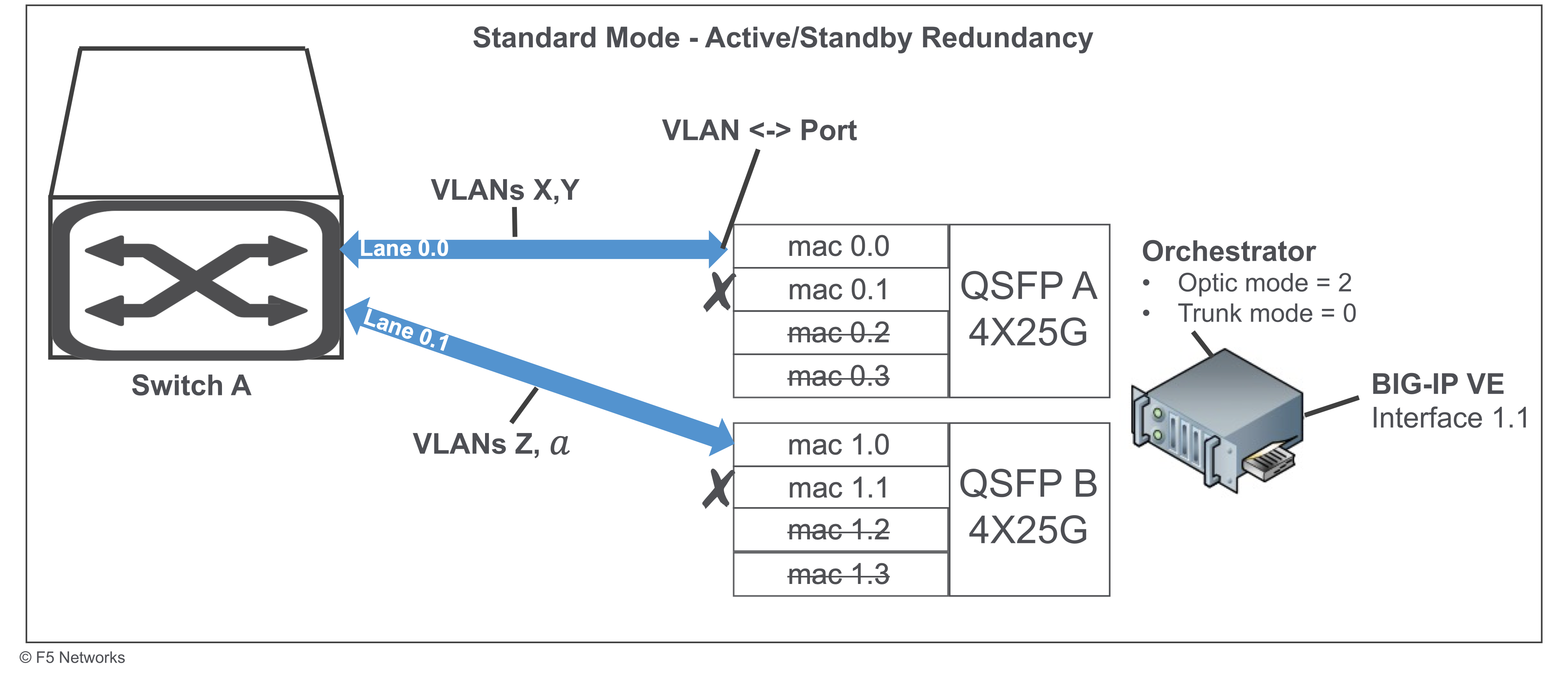
Standard mode active/standby redundancy for 1-optic
The following diagram describes the standard mode active/active redundancy configuration with:
- A maximum throughput of 25G+
- Active/Standby Redundancy
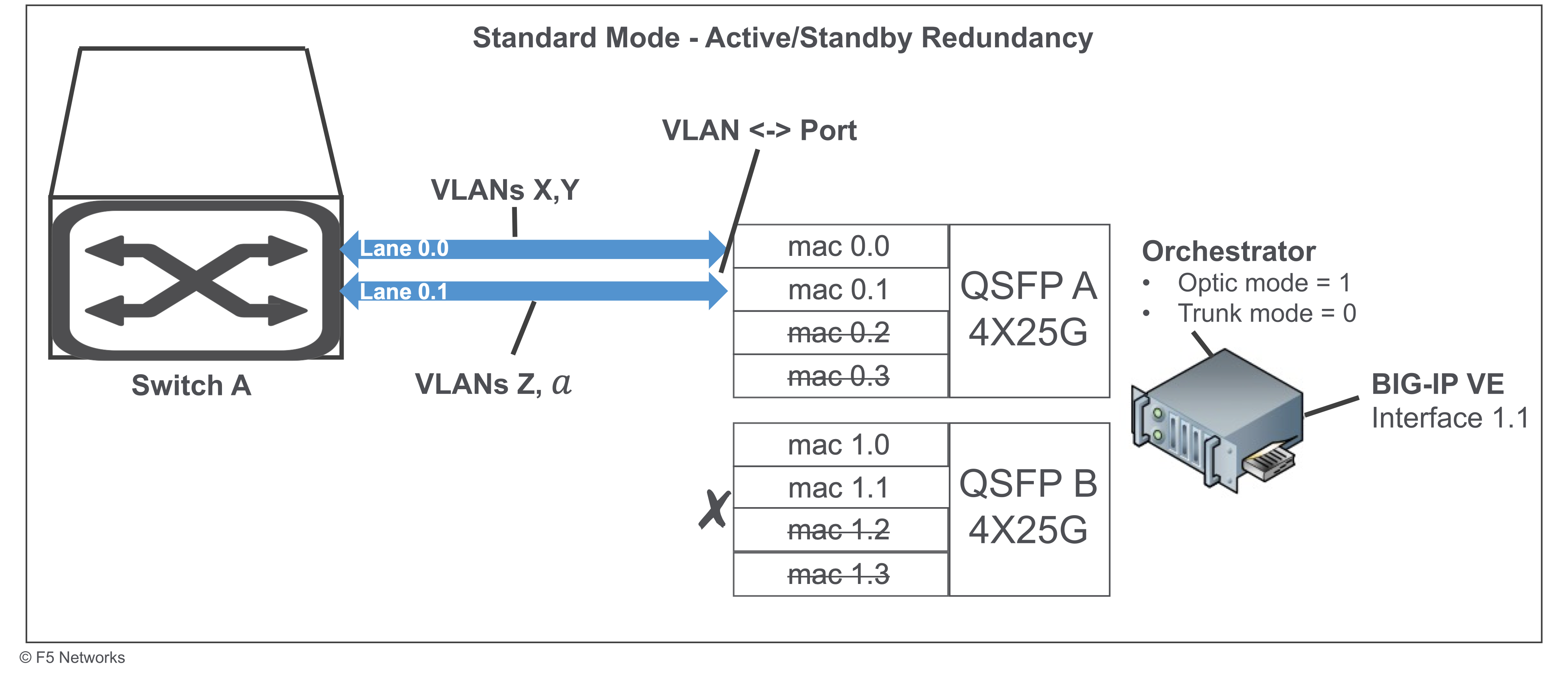
VLAN <-> port - mapping is learned in the hardware and determines the egress MAC Port assignment.
BIG-IP VE interface 1.1 - is the virtual function of the primary physical function for:
- Active VLANs = X,Y
- Standby VLANs = Z,𝑎
Important
- Only mac 0.0 contains active traffic with VLANs X,Y. Only mac 0.1 keeps live packets, so FPGA can learn that the mac 0.1 port has VLANs Z,𝑎 associated with it.
- If 25G lane 0.0 is down, then BIG-IP VE must fail over to use VLANs Z,𝑎 for traffic, so FPGA can learn the mac 0.1 port assigned to VLANs Z,𝑎.
2-optic mode
2-optic mode has the following options:
- Standard mode without redundancy
- Trunk mode without redundancy
- Standard mode with active/active redundancy
- Standard mode with active/standby redundancy
Standard mode for 2-optic
The following diagram describes the standard mode configuration with:
- A maximum throughput of 25G
- No redundancy
- VLAN <-> port - mapping is learned in the hardware and determines the egress MAC Port assignment.
- BIG-IP VE interface 1.1 - is the virtual function of the primary physical function for VLANs X,Y.
Trunk mode for 2-optic
The following diagram describes the trunk mode configuration with:
- A maximum throughput of 50G
- No redundancy
- 25G lanes - use the switch to aggregate lanes 0.0 and 0.1.
- Hash determines the egress MAC Port.
- BIG-IP VE interface 1.1 - is the virtual function of the primary physical function for VLANs X,Y.
Standard mode active/active redundancy for 2-optic
The following diagram describes the standard mode active/active redundancy configuration with:
- A maximum throughput of 25G+
- Active/Active Redundancy
VLAN <-> port - mapping is learned in the hardware and determines the egress MAC Port assignment.
25G lanes - OPTIONAL you can use the switch to aggregate lanes 0.0 and 0.1 to share same VLANs.
BIG-IP VE interface 1.1 - is the virtual function of the primary physical function for VLANs X,Y.
Important
- If 25G lanes 0.0 or 1.0 are up and active and the switch is sending traffic down each lane based on a hash, then the FPGA is constantly switching the egress port for a particular VLAN.
- If one 25G lanes 0.0 or 1.0 is down, then the switch only sends traffic to the lane that is up. The FPGA learns the appropriate egress port of where active traffic is, so you can maintain at least 25G of connectivity.
Standard mode active/standby redundancy for 2-optic
The following diagram describes the standard mode active/active redundancy configuration with:
- A maximum throughput of 25G+
- Active/Standby Redundancy
VLAN <-> port - mapping is learned in the hardware and determines the egress MAC Port assignment.
BIG-IP VE interface 1.1 - is the virtual function of the primary physical function for:
- Active VLANs = X,Y
- Standby VLANs = Z,𝑎
Important
- Only mac 0.0 contains active traffic with VLANs X,Y. Only mac 1.0 keeps live packets, so FPGA can learn the mac 1.0 port assigned to VLANs Z,𝑎.
- If 25G lane 0.0 is down, then BIG-IP VE must fail over to use VLANs Z,𝑎 for traffic, so the upstream Switch A can start sending traffic down mac lane 1.0.
What’s next?