F5 Application Delivery Controller Solutions > BIG-IP HA - Do it the Proper Way > Intro to: BIG-IP HA - Do it the Proper Way Source | Edit on
Lab 2: Configure Device Service Cluster (DSC) High-Availability Settings
In Lab 2, we will configure DSC configuration objects, which will assist with establishing a device-trust between BIG-IPs, allowing a successful highly-available Active/Standby BIG-IP pair.
For addtional details on DSC, please refer to this Article: BIG-IP Device Service Clustering: Administration
Lab Tasks:
- Task 1: Define DSC HA Settings
- Task 2: Configure & Verify Device Trust
- Task 3: Configure the Device Group
- Task 4: Modify Self IP Port Lockdown on Data Self IPs
- Task 5: Add the Management Address to the Failover Network
- Task 6: Create Floating Self IPs
- Task 7: Validate the Device Group Status & Synchronize BIG-IPs
Task 1: Define Device Service Cluster High-Availability Settings
In Task 1, we will define our respective DSC configuration items on each respective BIG-IP.
Use the following table for the respective configuration objects:
Note
Initially, we will ONLY add our Data Interfaces to the Failover Network. This will showcase communication between BIG-IPs. Management IP will be added in Task 5 below.
| Device Management Settings: | Configuration Item / Object | BIG-IP-A IP's | BIG-IP-B IP's |
|---|---|---|---|
| ConfigSync [Local Address] | HA_vlan_30 | 10.1.30.241 | 10.1.30.242 |
| Failover Network [Unicast Config] | Management Address: int_vlan_10: ext_vlan_20: |
10.1.1.5 10.1.10.241 10.1.20.241 |
10.1.1.6 10.1.10.242 10.1.20.242 |
| Mirroring [Primary Local Mirror Address] | HA_vlan_30 | 10.1.30.241 | 10.1.30.242 |
Navigate to: Device Management > Devices > click the (Self) hyperlink:
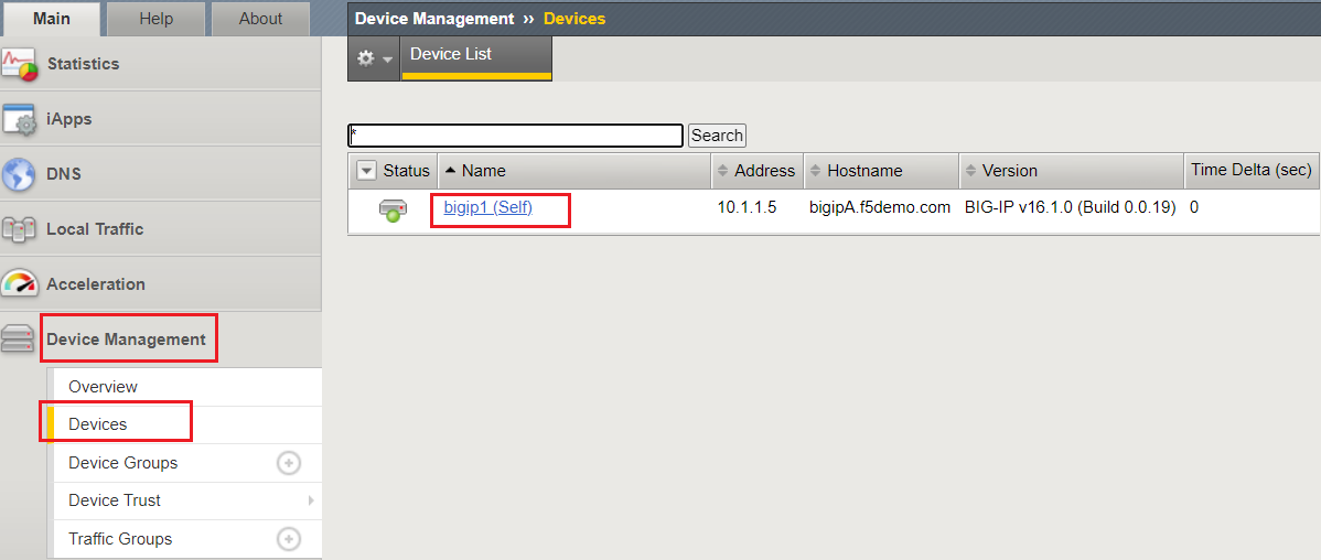
If your device name is still the default name "bipip1," click the Change Device Name button:
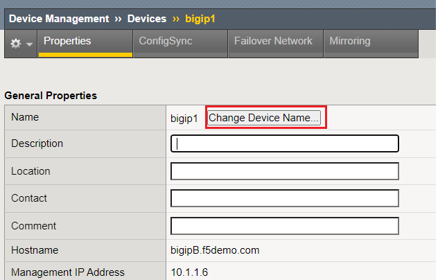
Provide the BIG-IP FQDN as the "New Name," change the Certificate drop-down to Generate New Self-Signed Authority, and click the Update button:
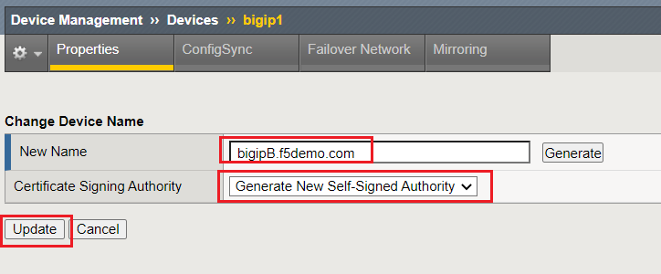
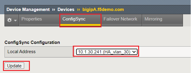
Click the "ConfigSync" banner:
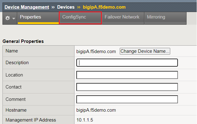
Under the Local Address drop-down, select the HA VLAN 30 address, then click the Update button:
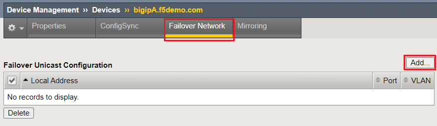
Now, we will ONLY add our Data Interfaces to our Failover Network configuration, initially. We will observe the BIG-IP behavior afterwards. This will showcase failover communication.
Click the "Failover Network" banner, then the Add button:
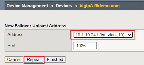
From the New Failover Unicast Address drop-down, select the data-plane VLAN 10 address and click the Repeat button:
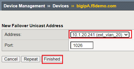
From the New Failover Unicast Address drop-down, select the data-plane VLAN 20 address; click the Finished button:
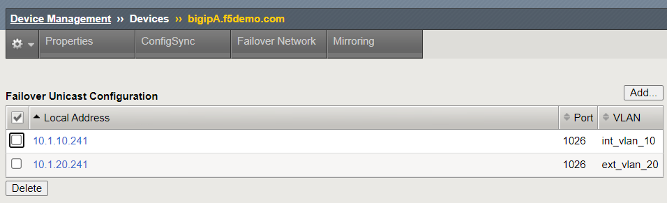
View of the Failover Unicast Configuration, with only the Data Interfaces:
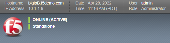
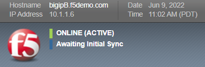
Observe the current state of each BIG-IP:
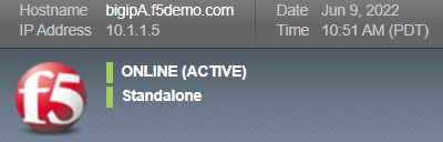
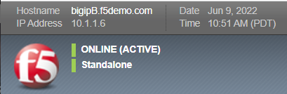
| Question: | Why are both BIG-IPs still ACTIVE / Standalone? |
|---|---|
| Answer: | Currently, there is no Device Trust between BIG-IPs, so they do not "see" one another. We must establish Device Trust in the next Task. |
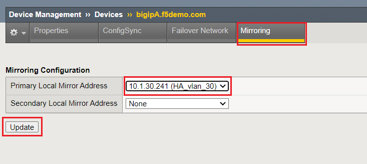
Click the "Mirroring" banner:
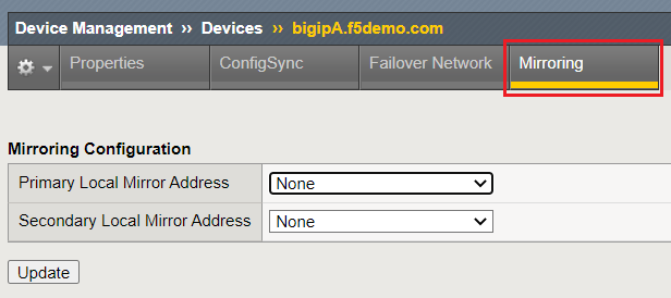
From the Primary Local Mirror Adddress drop-down, select the HA VLAN 30 address, and click the Update button:
Upon completion of this Task, both BIG-IPs should remain in an ACTIVE and Standalone state. We must establish the Device Trust in the next Task to successfully create our Active/Standby BIG-IP HA pair.
Note
- To take advantage of Connection Mirroring, there are addtional BIG-IP configuration items to configure, specifically as it relates to the Virtual Server. We will address this configuration in Lab 3.
- For information on enabling connection mirroring for your Virtual Server, please refer to this link, Enable connection mirroring for a virtual server
- For more information on Connection Mirroring Configuration, please refer to Knowledge Article K84303332
Task 2: Configure & Verify Device Trust between BIG-IPs
Now we will define the configuration to establish our device-trust between BIG-IPs.
On device bigipB.f5demo.com, setup the Device Trust that will be used between BIG-IP systems
Note
Observe the current status of EACH BIG-IP. Prior to this Task, they are both in an ACTIVE / Standalone state. Throughout this setup, observe the changes in BIG-IP behavior.
| State | Notes | bigipA | bigipB |
|---|---|---|---|
| Prior to DSC configuration | Both devices in "Standalone" state | 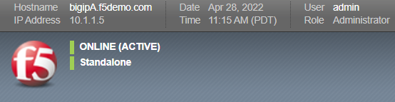
|
|
| During device peer join trust | Both devices enter "Disconnected" state | 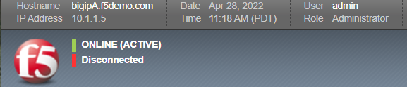
|
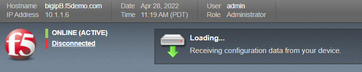
|
| After device peer join trust | Both devices enter "Active / In Sync" state | 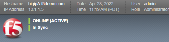
|
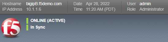
|
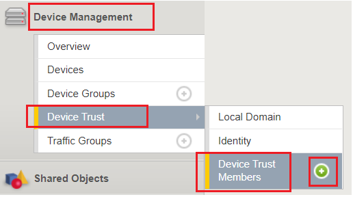
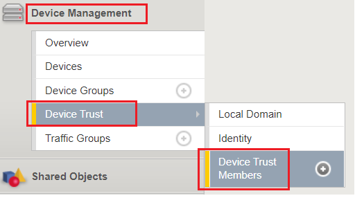
Navigate to: Device Management > Device Trust > Device Trust Members page, then click the "+" button to create a new Peer Device:
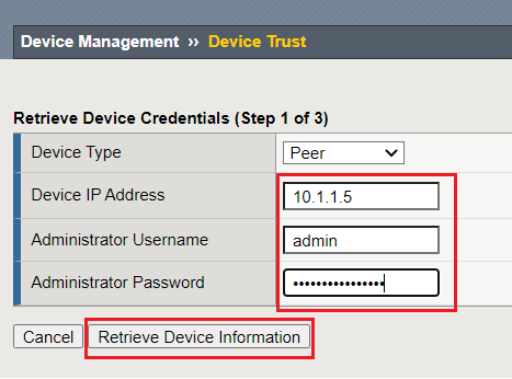
Retrieve Device Credentials (Step 1 of 3):
Fill in the respective configuration items for bigipA.f5demo.com, then click the Retrieve Device Information button
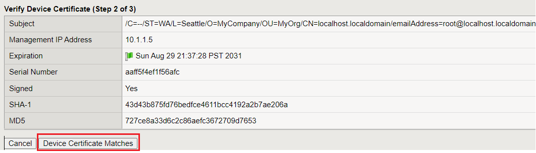
Verify Device Certificate (Step 2 of 3):
Confirm the device certificate information, then click the Device Certificate Matches button
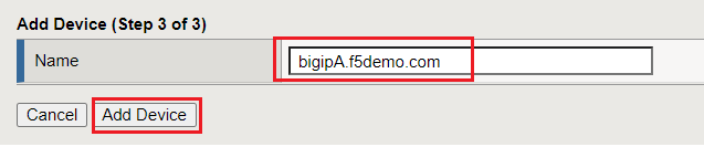
Add Device (Step 3 of 3):
Verify the device name, and click the Add Device button
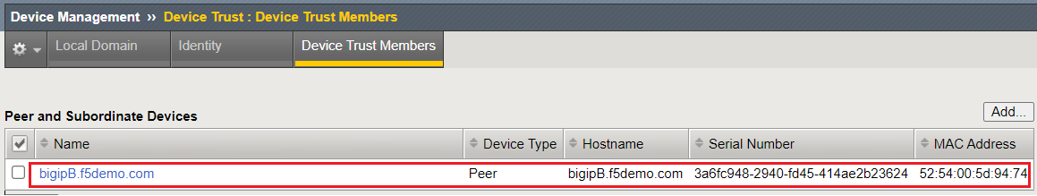
On bigipA.f5demo.com, verify Device Trust shows BIG-IP-B:
Navigate to: Device Management > Device Trust > Device Trust Members
Verify that bigipB.f5demo.com is shown in the Peer Device List:
| Question: | Why are both BIG-IPs Active / In Sync? |
|---|---|
Answer:
|
ConfigSync is communicating across HA VLAN, allowing Centralized Management Infrastructure (CMI) communication on TCP port 4353 (iQuery), so both BIG-IPs think sync-state is good.
There is no Device Group established between the BIG-IPs yet, so they remain in an Active/Active state. We will establish Device Group in the next task.
|
Bonus:
|
The local mcpd process connects to the local TMM process using TCP port 6699. The local TMM then creates secure connections to remote CMI peer TMMs using TCP port 4353.
Note: CMI is also referred to as device service clustering (DSC).
08:39:05.368035 IP 10.1.30.241.4353 > 10.1.30.242.64426: Flags [.], ack 408, win 24252, length 0 in slot1/tmm1 lis=_cgc_outbound_/Common/bigipA.f5demo.com_6699 port=HA_trunk trunk=
08:39:05.368155 IP 10.1.30.242.64426 > 10.1.30.241.4353: Flags [.], ack 151, win 15559, length 0 out slot1/tmm1 lis=_cgc_outbound_/Common/bigipA.f5demo.com_6699 port=1.3 trunk=HA_trunk
[root@bigipB:Active:In Sync (Trust Domain Only)] config # netstat -a | grep 6699
tcp6 0 0 localhost.localdom:6699 [::]:* LISTEN
tcp6 0 0 10.1.30.242:53398 10.1.30.241:6699 ESTABLISHED
tcp6 0 0 localhost.localdom:6699 10.1.30.241:42792 ESTABLISHED
|
Task 3: Configure the Device Group
In Task 3, we will define the device group on the BIG-IPs.
On bigipA.f5demo.com, set up the new Device Group that will be used by both BIG-IP systems.
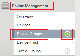
Navigate to: Device Management > Device Groups page, and then click the "+" button:
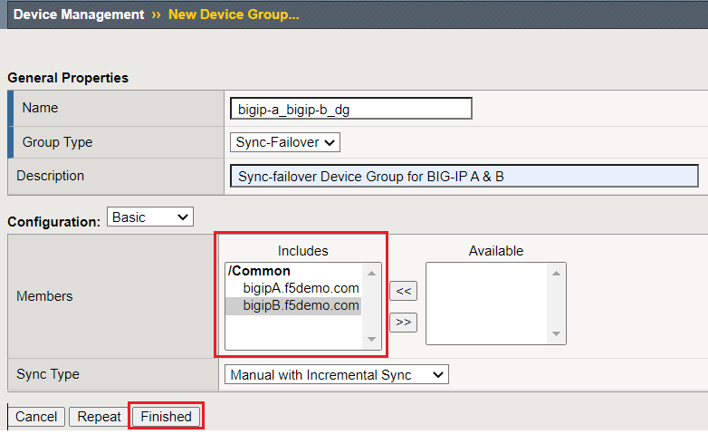
Create a Device Group using the following information, and then click Finished button:
Name bigip-a_bigip-b_dg Group Type Sync-Failover Description [OPTIONAL] Sync-failover Device Group for BIG-IP A & B Members Move both bipipA & bipipB from the Available column to the Includes column 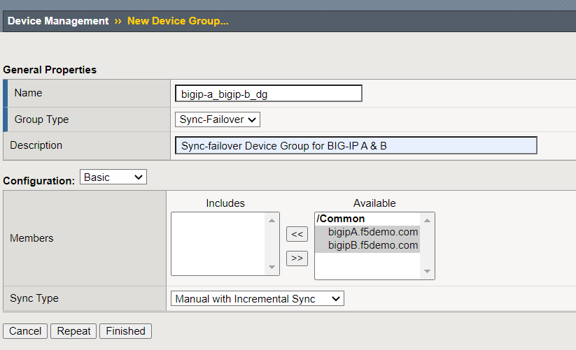
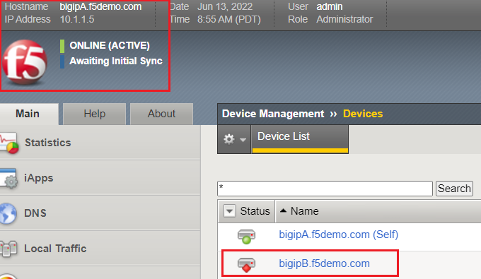
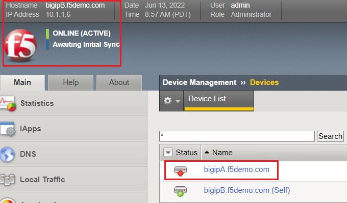
Observe the current state of each BIG-IP.

| Question: | Why are both BIG-IPs ACTIVE and Awaiting Initial Sync? |
|---|---|
| Answer: | Both BIG-IPs still cannot "see" their peer due to the current Self IP port lockdown settings on the Data Self IPs. Each BIG-IP sees its peer as "offline" from the Device Management > Devices overview page |
To confirm each BIG-IP cannot "see" its peer, Navigate to: Device Management > Devices, and review the Status of the respective BIG-IP peer:
In the next Task, we will modify our Self IP port lockdown settings on our Data Self IPs. This will allow the BIG-IPs to communicate across the Failover IPs.
Task 4: Modify Self IP Port Lockdown on Data Self IPs:
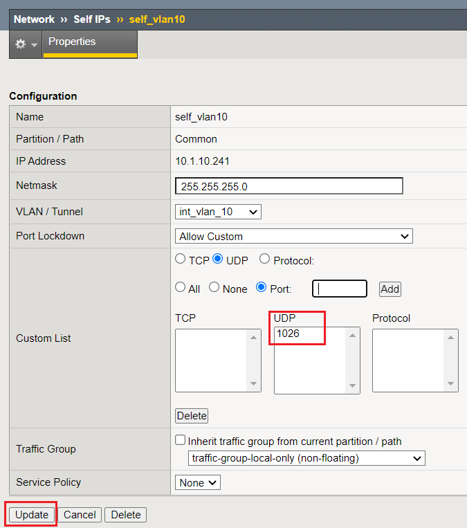
In Task 4, we will modify our "Allow None" Self IP port lockdown behavior of the Data Self IPs; we will define a Custom Port Lockdown configuration on the respective Self IPs.
For optimal security, F5 recommends that you use the port lockdown feature to allow only the protocols or services required for a self IP address.
Note
For our Data VLANs (internal & external), we will "Allow Custom", allowing UDP protocol on port 1026
There are port lockdown exceptions to be aware of. Please review Knowledge Article K17333 for further details.
In Lab 1, when we created our Local Self IPs, we chose to select the "Allow None" port lockdown behavior. As a result of this, the BIG-IP is preventing DSC communication between BIG-IPs. In this Task, we will modify our port lockdown configuration, which will allow DSC communication between BIG-IPs.
On each BIG-IP, Navigate to: Network > Self IPs:
Modify both the Internal & External Self IP Port Lockdown settings by clicking their respective hyperlink to modify the item.
Change from "Allow None" to "Allow Custom"
- From the Port Lockdown drop-down, select "Allow Custom."
- Click the radio button for UDP.
- Click the radio button for Port.
- In the Port field, enter 1026.
- Click Add.
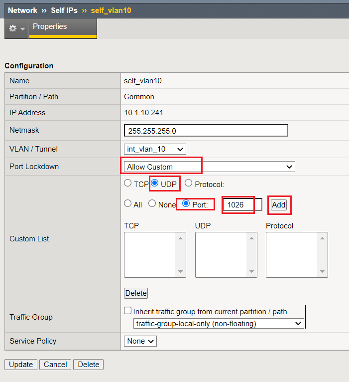
You should see "1026" listed in the UDP Custom List section. Click the Update button:
Repeat this step on the External VLAN
Upon completion of this Task, you should observe that the BIG-IPs can start to communicate on UDP port 1026. Your BIG-IPs should be in an ACTIVE/STANDBY, Awaiting Initial Sync state after this task:
- BIG-IP-A (is Standby)
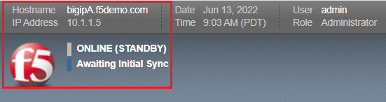
- BIG-IP-B (is Active)
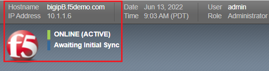
Perform the recommendation synchronization, and confirm your BIG-IPs are ACTIVE/STANDBY and In Sync:
- BIG-IP-A (is Standby)
- BIG-IP-B (is Active)
This task validates that your Failover communication must be allowed on UDP port 1026 between BIG-IPs.
Task 5: Add the Management Address to the Failover Network
In Task 5, we will add an addtional address to our Failover Network configuration. We will add the Management Address, which will provide an addtional failover path for communication on UDP port 1026.
Note
BIG-IP Management Address does not have any default port lockdown settings. If we were to have added this in Task 1, we would have formed a failover communication path on the management IP, allowing the BIG-IPs to communicate. We wanted you to observe how port lockdown settings can affect BIG-IP communication.
- Navigate to: Device Management > Devices > click local BIG-IP (Self) hyperlink, then click the Failover Network banner, then click the Add button:
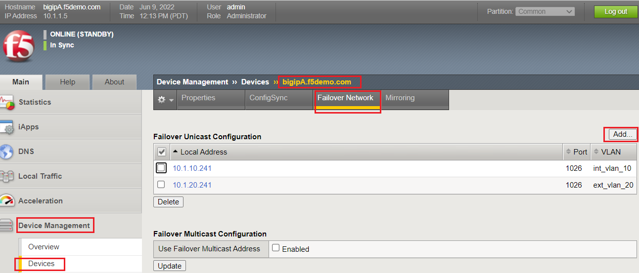
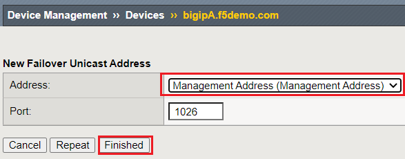
- From the Address drop-down, select the Management Address, and click the Finished button:
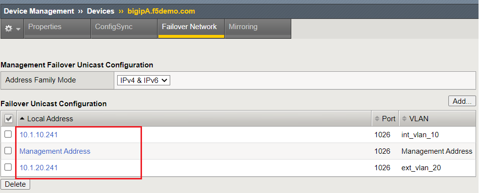
- Upon completion of this Task, you should have three IPs in your Failover Unicast Configuration
Task 6: Create Floating Self IPs
In this task, we will define Floating Self IP Objects on the ACTIVE BIG-IP, which are shared objects between an Active/Standby BIG-IP pair.
Floating Self IPs are shared objects between BIG-IPs, passing data traffic to the respective ACTIVE BIG-IP. It is a recommended best practice to define a respective floating Self IP object per data segment/VLAN.
For more detailed information regarding Floating Self IPs, please refer to this article: Self IP Addresses
Note
Only creating Floating Self IPs on ACTIVE BIG-IP. We will then synchronize these settings, proving our DSC communication.
- Use the following table to create the Floating Self IP Objects:
Note
DO NOT modify the Floating Self IP Address port lockdown. The Floating Self IP address port lockdown status has to be Allow None
| BIG-IP | Name | IP address | Netmask | VLAN | Port Lockdown | Traffic Group |
|---|---|---|---|---|---|---|
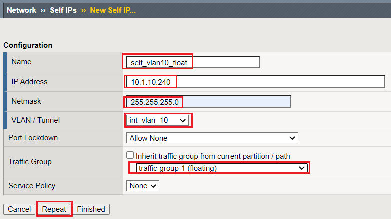
| [Active]bigip | self_vlan10_float | 10.1.10.240 | 255.255.255.0 | int_vlan_10 | Allow None (default) | traffic-group-1 (floating) |
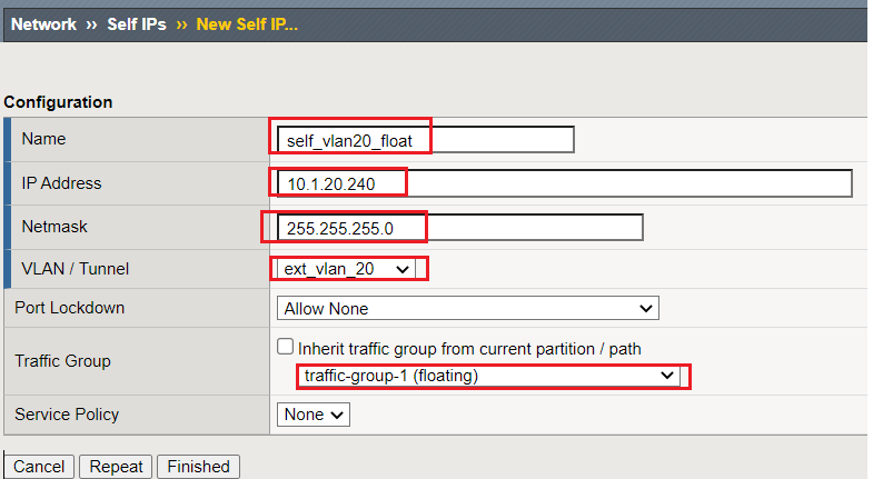
| [Active]bigip | self_vlan20_float | 10.1.20.240 | 255.255.255.0 | ext_vlan_20 | Allow None (default) | traffic-group-1 (floating) |
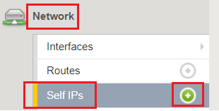
Navigate to: Network > Self IPs, then click the "+" button to create a new Self IP:
Create the respective Self IPs per the table above.
VLAN 10 Float:
VLAN 20 Float:
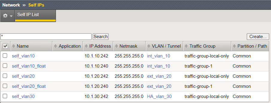
After creation of your Floating Self IPs, your Self IP List should reflect the following on the ACTIVE BIG-IP:
Task 7: Validate the Device Group Status & Synchronize BIG-IPs
In this lab, we have setup BIG-IP Device Trust, and we have created "shared BIG-IP" objects.
In this task, you will observe the current Active/Standby HA state, and synchronize the BIG-IP HA pair.
Observe the state of each BIG-IP after Device Group creation
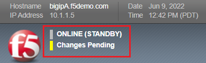
bigipA:
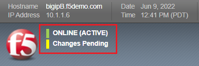
bigipB:
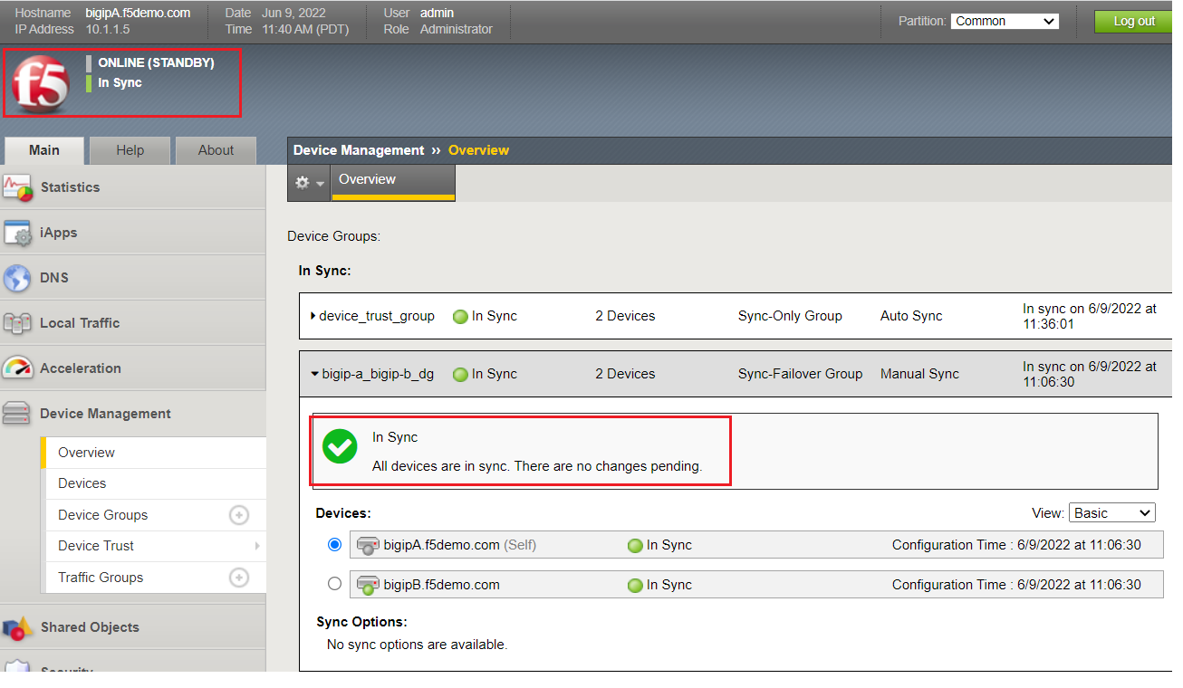
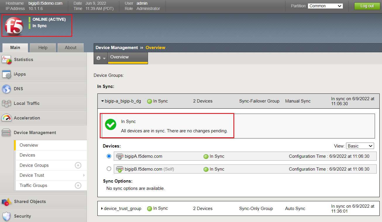
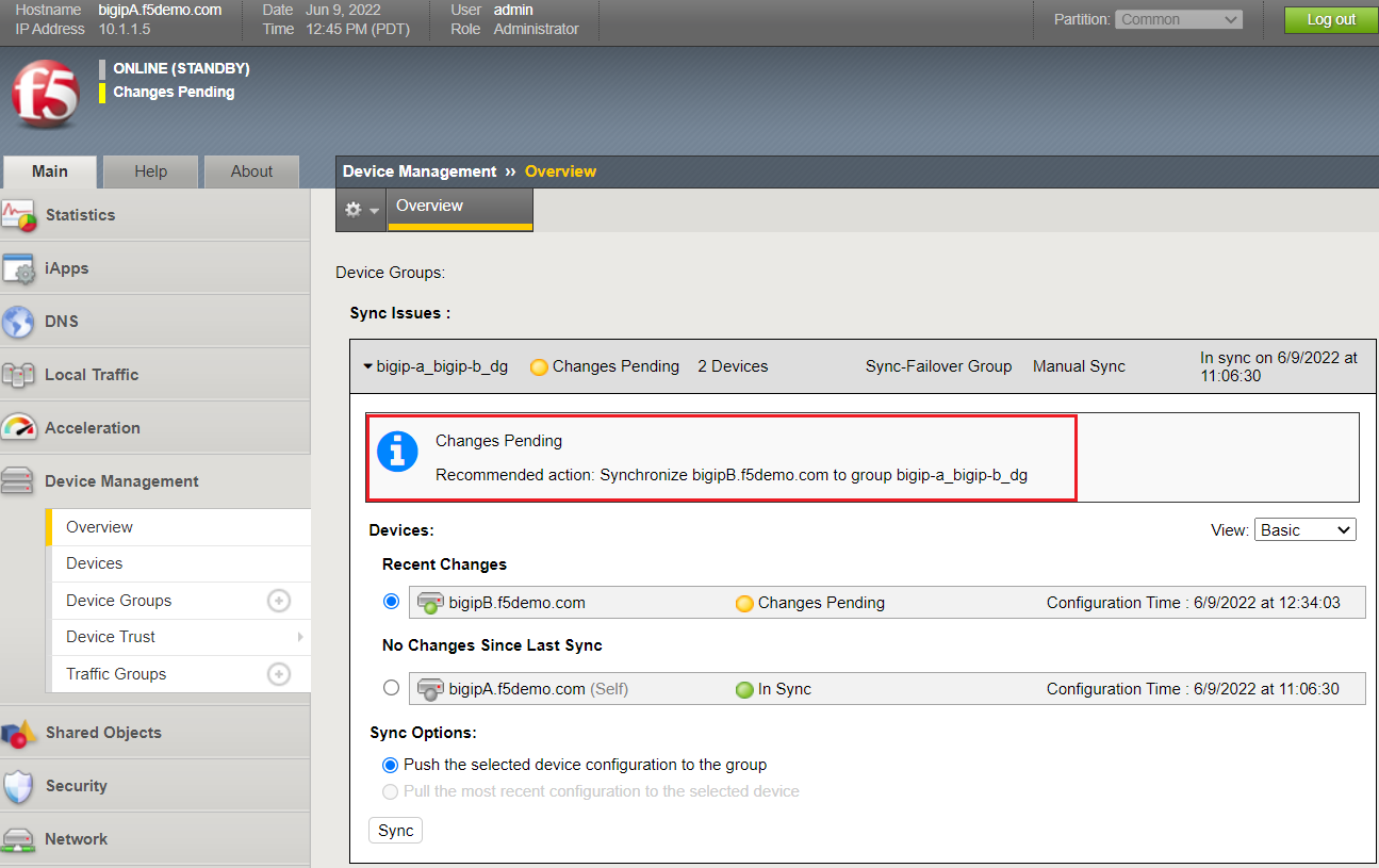
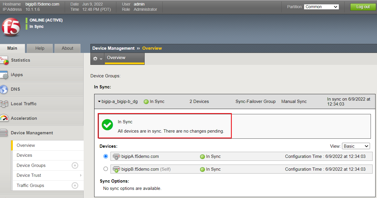
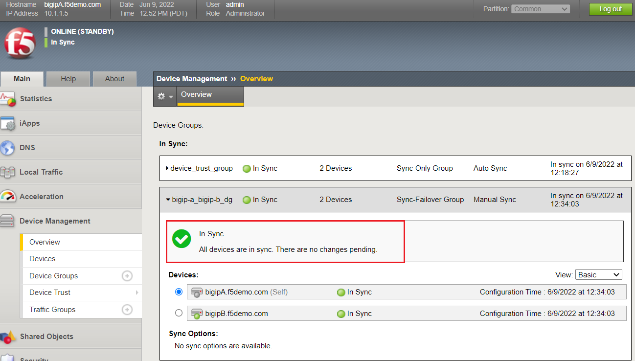
Review the Device Management Overview screen
Navigate to: Device Management > Overview:
bigipA:
bigipB:
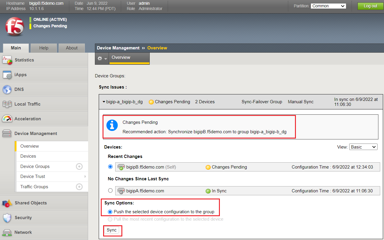
Attempt the "Recommendation action", and click the Sync button:
| Question: | Were you able to syncronize the devices? |
|---|---|
| Answer: | Yes, we have established successful communication between BIG-IPs |
Validate Devices are In Sync from the Overview page:
bigipA:
bigipB:
Lab Summary
In this lab, you setup basic BIG-IP Device Service Clustering (DSC) configuration settings. After completion of these lab tasks, you should have the required configuration to assist in establishing your DSC between BIG-IPs. Upon completion of this Lab, you should have an Active/Standby, In Sync BIG-IP HA pair.
This completes Lab 2.