Nutanix AHV: BIG-IP Virtual Edition Setup
Important
The following topics demonstrate the required tasks using Nutanix AOS 5.20. See the Nutanix AOS 6.5 documentation for updated support information.
To deploy F5® BIG-IP® Virtual Edition (VE) on Nutanix Acropolis Hypervisor (AHV) AOS 5.20 and 6.5 LTS, you will perform these tasks:
| Step | Details |
|---|---|
| 1 | Choose the license you want to buy, the BIG-IP VE modules you want, and the throughput you need. See K14810: Overview of BIG-IP VE license and throughput limits on the AskF5 Knowledge Base for details. |
| 2 | Confirm that you are running a hypervisor version that is compatible with a BIG-IP VE release. See BIG-IP Virtual Edition Supported Platforms for details. |
| 3 | Verify that the host hardware meets the recommended requirements. |
| 4 | Download a supported BIG-IP VE ALL.qcow2 image from F5 Downloads page and extract all files to your local machine. |
| Login to your Nutanix PRISM console to upload BIG-IP VE image. | |
| Import the BIG-IP image. | |
| Create a VM and attach subnets. | |
| Launch the BIG-IP configuration tool | |
| License the BIG-IP (see K7752 article for steps). | |
| Set up the BIG-IP HA pair. |
Prerequisites for BIG-IP Virtual Edition
Nutanix Acropolis Hypervisor hardware platforms are KVM-based, and MUST meet the following KVM system requirements.
Caution
Nutanix Acropolis Hypervisor hardware platforms are subject to change without F5’s knowledge.
Host CPU requirements
The host hardware CPU must meet the following requirements.
- The CPU must have 64-bit architecture.
- The CPU must have virtualization support (AMD-V or Intel VT-x) enabled in the BIOS.
- The CPU must support a one-to-one, thread-to-defined virtual CPU ratio, or on single-threading architectures, support at least one core per defined virtual CPU.
- If your CPU supports the Advanced Encryption Standard New Instruction (AES-NI), SSL encryption processing on BIG-IP VE will be faster. Contact your CPU vendor for details about which CPUs provide AES-NI support.
- Set CPU appropriately for the required MHz per core. For example, if the hypervisor has 2.0GHz cores, and the VE is set to 4 cores, you will need 4x2.0GHz reserved for 8GHz (or 8000MHz).
Host memory requirements
| Number of cores | Memory required |
|---|---|
| 1 | 2 Gb |
| 2 | 4 Gb |
| 4 | 8 Gb |
| 8 | 16 Gb |
Upload the BIG-IP VE image
The following steps demonstrates this process using Nutanix AOS 5.20. For updated steps, see the AOS 6.5 Nutanix documentation.
Log into the Nutanix AHV PRISM console.
On the top menu, expand , and then select the Image configuration option.
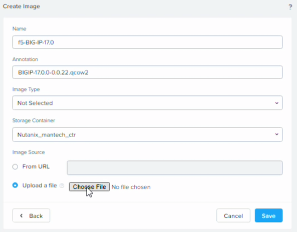
On the Nutanix AHV PRISM Image Configuration window, click Upload Image, name and annotate your image, select Upload a file, click Choose file and select the extracted BIG-IP ALL.qcow2 file, and then click Save.
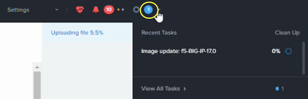
To view the upload progress, in the top menu, expand the file alert icon:
Import the BIG-IP VE image
The following steps demonstrates this process using Nutanix AOS 5.20. For updated steps, see the AOS 6.5 Nutanix documentation.
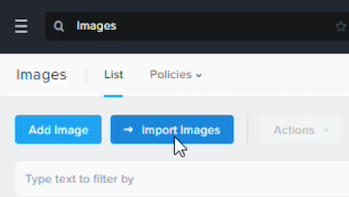
On the list of all uploaded images, on the top menu, click Import images.
On the import images popup dialog, select the Images on a Cluster option, select the cluster-image option you want to import, and then click the Select images link.
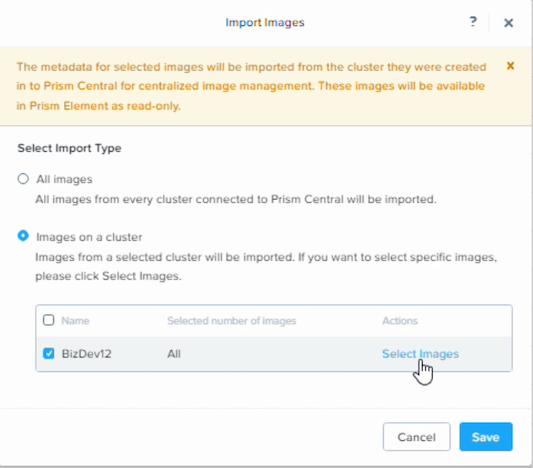
At the popup list of all images on a cluster, at the top of the list, click to clear the Name check box that deselects all files in the cluster.
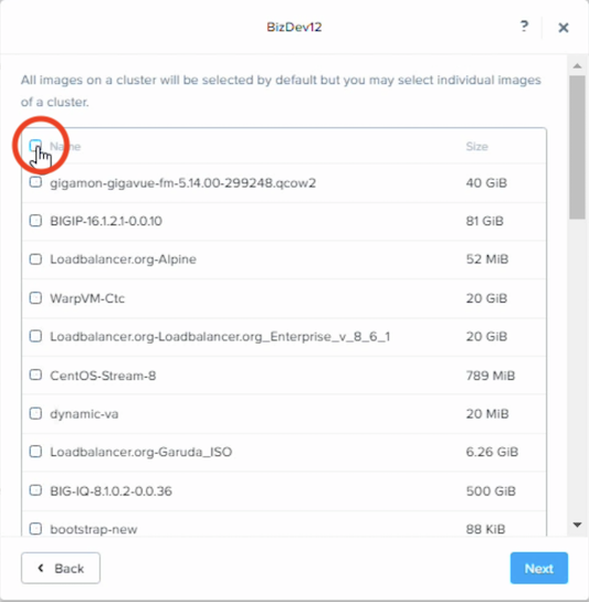
Scroll the list and select the BIG-IP image in the list, click Next, and then click Save.
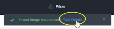
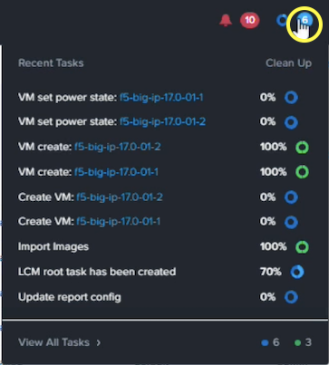
Do the following to view status of your imported image:
At the top of the window, click the Task Details:
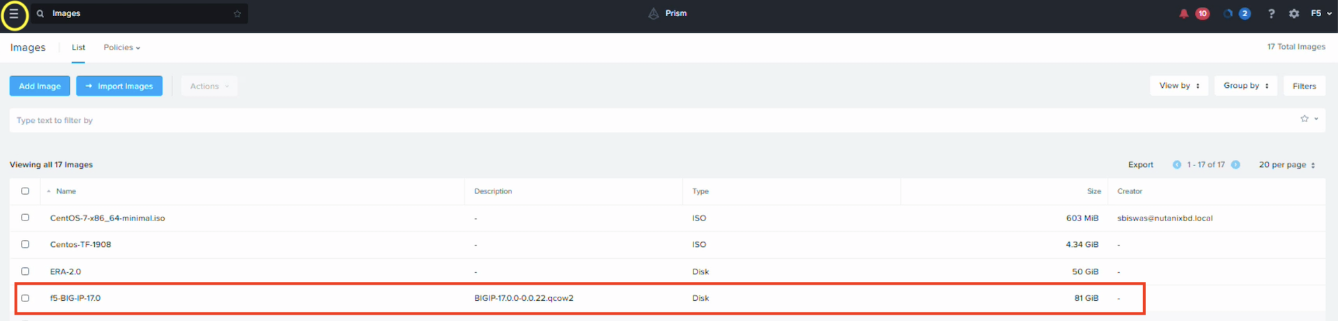
In the top-left corner, click More, and then select Images from the left menu, click the BIG-IP image in the list to view the size, type, etc.
Create a VM
The following process walks you through creating an example VM using Nutanix AOS 5.2. Use this VM for deploying a BIG-IP VE HA pair. You can set these values according to your system requirements. For updated steps, see the AOS 6.5 Nutanix documentation.
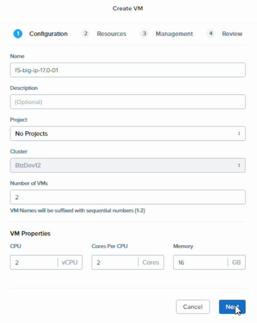
In the left menu click VMs, click Create VM, and then complete the popup dialog with a Name, Number of VMs set to 2, and then set the following VM Properties:
- CPU - 2 vCPU
- Cores per CPU - 2 cores
- Memory - 16GB
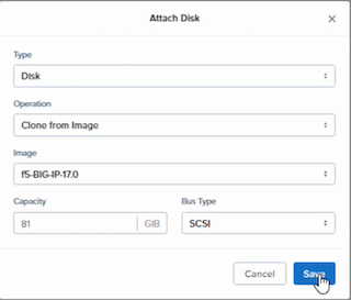
Click Next, on the Resource tab, click Attach Disk, complete the following, and then click Save:
- Type - Disk
- Operation - Clone from image
- Image - browse for and select the BIG-IP image
- Capacity - 81
- Bus - SCSI
In the Networks pane, click Attach to Subnet repeatedly to attach the following subnets (examples), and then click Save:
NR_PRT_DHCP
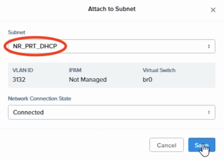
NR_PRT_STATIC
NR_INT_STATIC
NR_INT_DHCP
Note
Attach the interfaces to the subnets appropriate for your environment.
Click Next, on the Management tab, select the Use this VM as an Agent VM option, and then click Next.
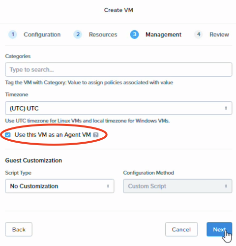
On the Review tab, click Create VM.
On the list of VMs page, do the following:
To view progress, in top-right corner click the blue icon.
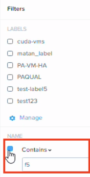
To filter the list of VMs, in the top-right corner click Filters, in the Name pane, select the Contains option, and in the text box enter F5.
Click the first BIG-IP VM-1 in the filtered list to view the Summary page, and then on the top menu, click Launch console to launch a Virtual Network Computing (VNC) client.
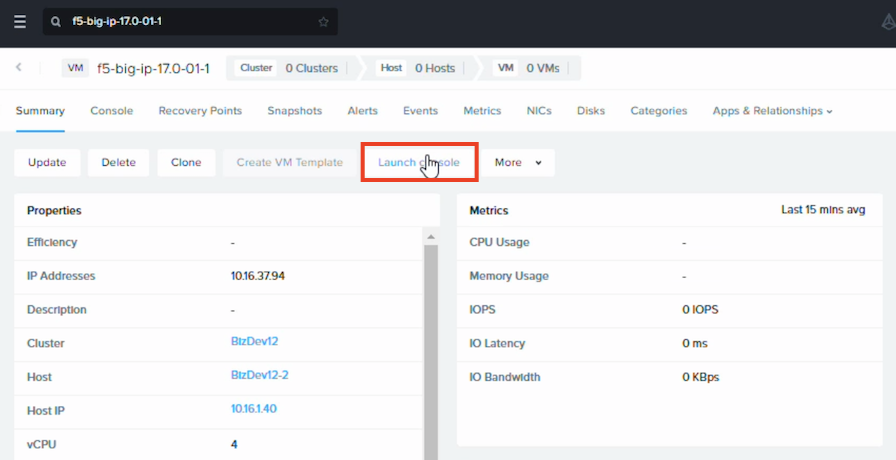
This opens a VNC client and displays the console in a new tab or window. Use this console to access BIG-IP configuration utility tool and set the management IP address.
Use the VNC client to access the BIG-IP Configuration utility tool and assign a management network IP address.
Important
You must repeat Steps 7-8 selecting the second BIG-IP VM-2 and assign the management network IP address.
Use BIG-IP configuration utility tool to set management IP address
If your network has DHCP, an IP address is automatically assigned to BIG-IP VE during deployment. You can use this address to access the BIG-IP VE Configuration utility or tmsh command-line utility.
If no IP address was assigned, you can assign one by using the BIG-IP Configuration utility tool.
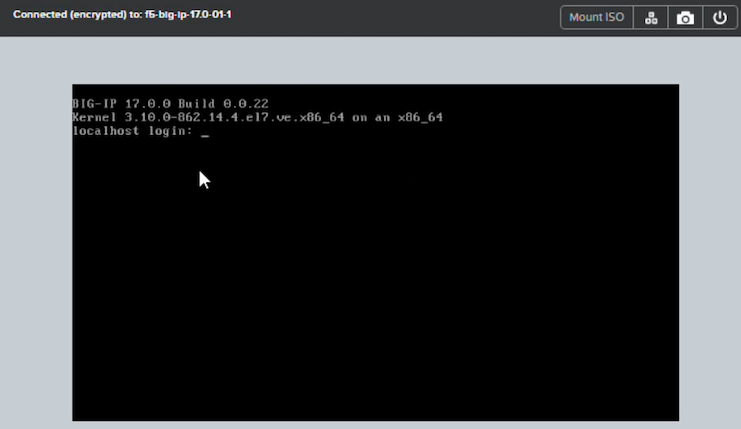
Connect to the virtual machine by using the hypervisor’s console.
At the login prompt, type
root.At the password prompt, type
default.Note
If prompted, change your password.
Type
configand press Enter.The F5 Management Port Setup screen opens.
Click OK.
Select No and follow the instructions for manually assigning an IP address and netmask for the management port.
You can use a hypervisor generic statement, such as
tmsh show sys management-ipto confirm that the management IP address was set properly.You can now log into the BIG-IP VE Config utility using a browser, and license and provision BIG-IP VE.
License your BIG-IP
To access the BIG-IP licensing utility in a browser window, use HTTPS:// and the IP address you assigned to the
management network using the BIG-IP Configuration utility.
Consult the K7752 article for complete licensing steps and video demo. You can also consult the Nutanix AVH: BIG-IP VE User’s Guide for information about reusing licenses, per-app licenses, virtual server options, and other similar licensing options.
Set up the BIG-IP HA pair
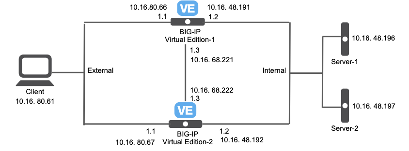
This example walks you through setting up two BIG-IP VEs for an HA pair, using the following example diagram and network configuration.
| Interface | VLAN | IP Address | Netmask | Gateway |
|---|---|---|---|---|
| Management | NR_PRT_DHCP | 10.16.36.221 - 10.16.36.225 | 255.255.240.0 | 10.16.32.1 |
| Internal | NR_PRT_STATIC | 10.16.48.191 - 10.16.48.200 | 255.255.240.0 | 10.16.48.1 |
| External | NR_INT_STATIC | 10.16.80.61 - 10.16.80.70 | 255.255.240.0 | 10.16.80.1 |
| HA | NR_INT_DHCP | 10.16.68.221-10.16.68.230 | 255.255.240.0 | 10.16.64.1 |
Note
The naming convention used is for demonstration purposes ONLY.
| Server type | IP Address |
|---|---|
| DNS | 10.16.0.200 |
| NTP | 10.16.0.211 |
Note
Other configuration notes include:
- Ignored the
dhcp-clientin the interface by usingNR_PRT_DHCPandNR_INT_DHCPand using a static IP (provided in the previous table). - For storage, used the
default-container-13584.
Creating an HA pair involves the following tasks:
- Set up BIG-IP-1 and BIG-IP-2
- Complete the HA connection
- Create an address pool and assigning members
- Sync configuration across device groups and test the connection
Set up BIG-IP-1
Do the following to configure the FIRST BIG-IP (1) in the HA pair setup:
In the F5 BIG-IP Setup utility, select , expand the Host Name drop-down list and select the BIG-IP host created in Nutanix.
In the Root Account, enter the root username and password, and then click Next.
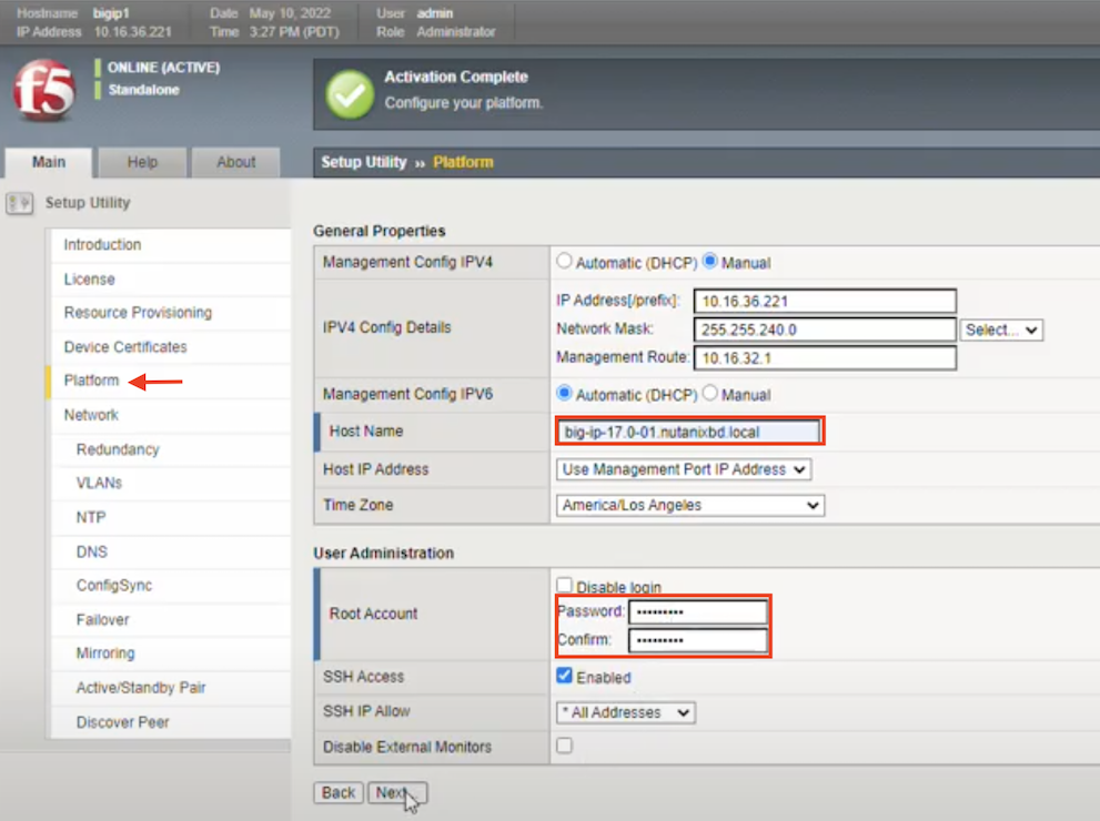
On the Network blade, in the Standard Network Configuration pane, click Next.
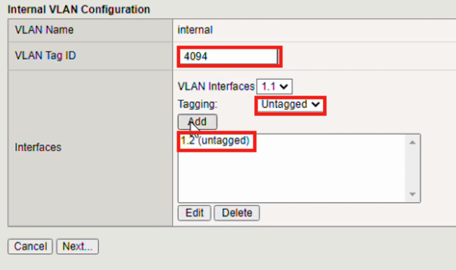
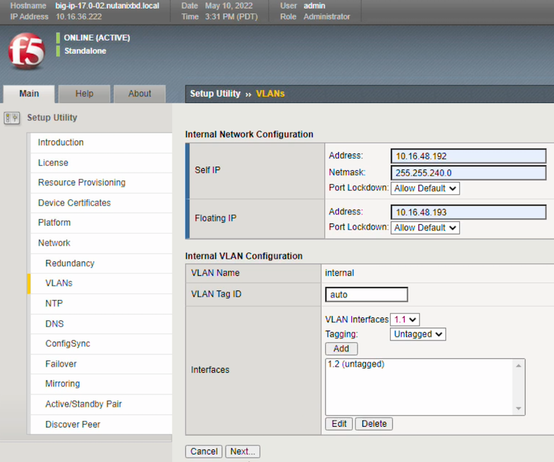
On the VLAN blade, do the following:
In the Internal VLAN Configuration pane, in the VLAN Tag ID text box, enter the tag number that identifies the traffic from hosts in the associated VLAN (for example, 4094), in the VLAN Interface text box, select 1.2, expand the Tagging drop-down menu, select Untagged.
Click Add, to add the VLAN to the Interfaces list.
In the Internal Network Configuration pane, do the following:
In the Self IP section, complete the following:
- Address - enter the IP address on the BIG-IP system that you want to associate with this VLAN
- Netmask - enter the associated netmask for the select address
In the Floating IP section, complete the following:
- Address - enter the IP address you want shared between multiple BIG-IP devices in a device group
- Port Lockdown - leave value as Allow Default
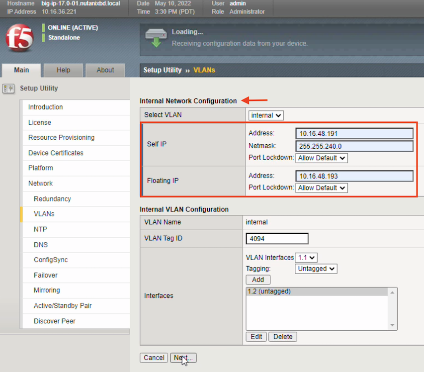
Click Next.
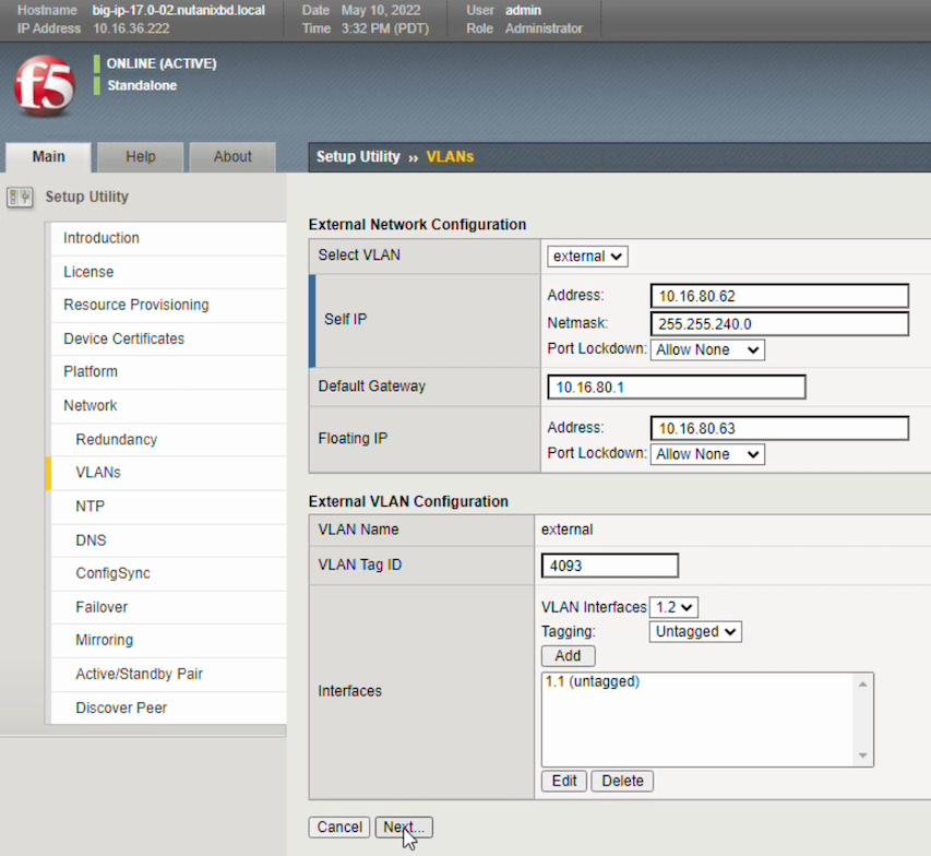
In the External Network Configuration pane, do the following:
- In the Self IP section complete the following:
- Address - enter the IP address on the BIG-IP system that you want to associate with this VLAN
- Netmask - enter the associated netmask for the select address
- Port Lockdown - leave value as Allow None
- In the Default Gateway section, enter an IP address.
- In the Floating IP section, complete the following:
- Address - enter the IP address you want shared between multiple BIG-IP devices in a device group
- Port Lockdown - leave value as Allow None
- In the Self IP section complete the following:
In the External VLAN Configuration pane, do the following:
Complete the following:
- VLAN Name - enter external
- VLAN Tag Name - leave the auto default value
- VLAN Interface - select 1.1
- Tagging - expand the list and select Untagged
Click Add to add the external VLAN to the Interfaces list.
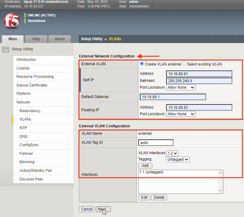
Click Next.
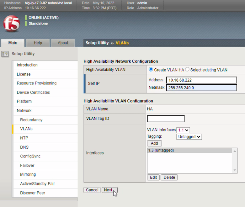
In the High Availability Network Configuration pane, do the following:
In the Self IP pane, complete the following:
- Address - enter the IP address on the BIG-IP system that you want to associate with this VLAN
- Netmask - enter the associated netmask for the select address
In the High Availability VLAN Configuration pane, complete the following:
- VLAN Name - Leave the HA default value
- VLAN Tag ID - leave the auto default value
- VLAN Interfaces - select 1.3
- Tagging - select Untagged
Click Add to add the VLAN to the Interfaces list.
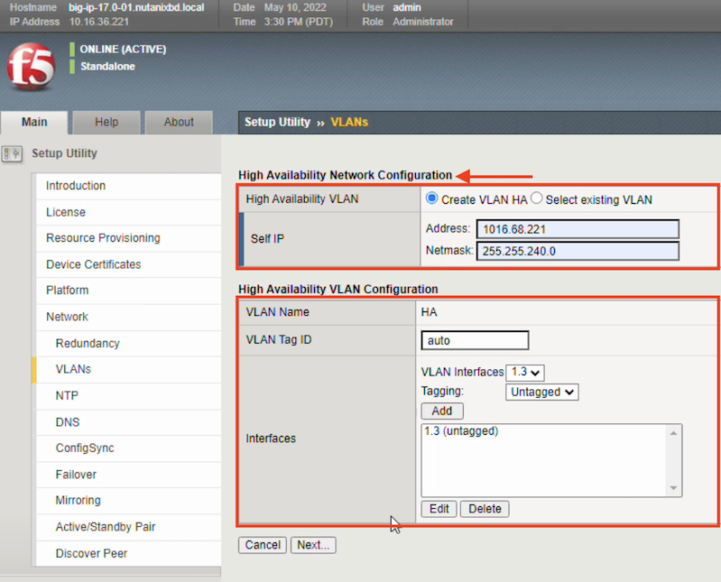
Click Next.
On the blade, in the Address text box, enter the address for the NTP server used, click Add to add it to the Time Server List, and then click Next.
On the blade, accept all default values, and then click Next (similar to the following example).
On the blade, accept the default Local Address (for example, 10.16.48.191 (internal)) value, and then click Next.
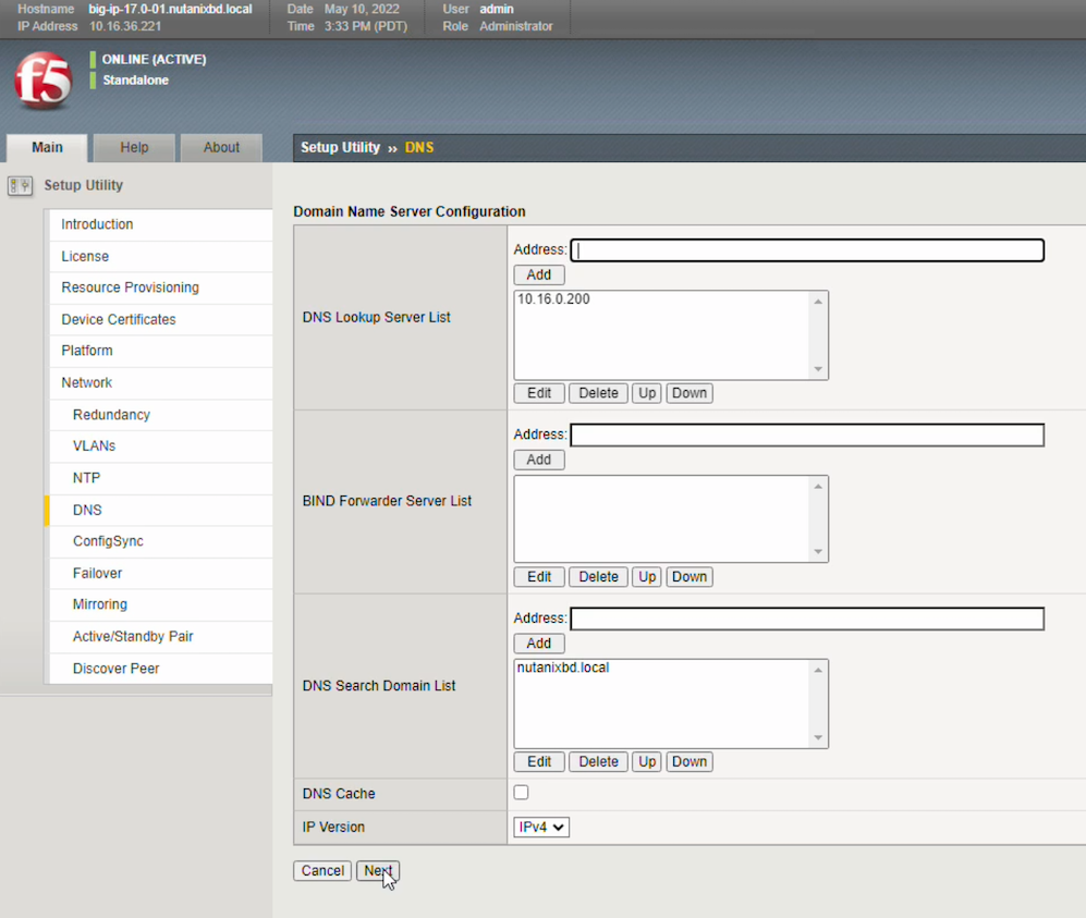
On the blade, accept all default values, and then click Next.
On the blade, accept all default values, and then click Next.
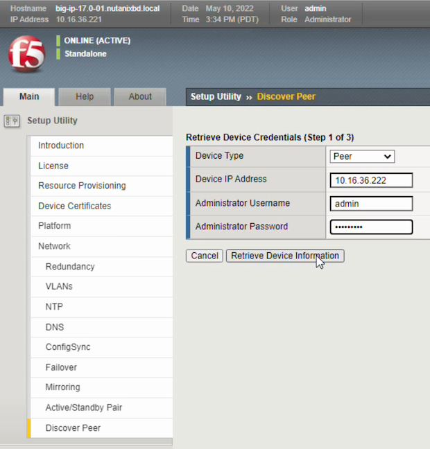
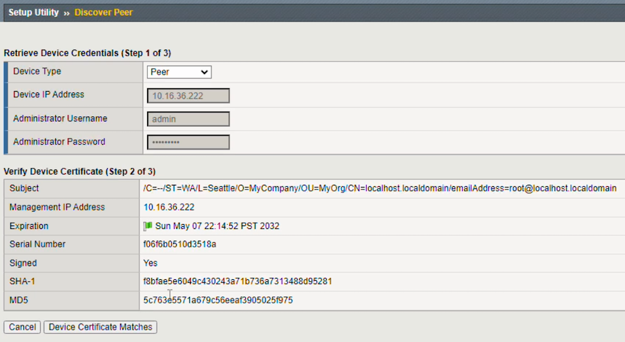
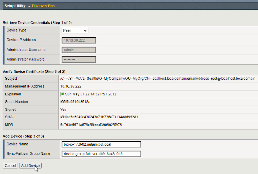
On the blade, click Next, on the Discover Peer blade, click Next, complete the following, and then click Retrieve Device Information:
- Device Type - select Peer
- Device IP Address - enter the device IP Address
- Administrator Username - enter the appropriate value
- Administrator Password - enter the appropriate value
Before proceeding, complete the second BIG-IP (2) setup.
Set up BIG-IP-2
Do the following to configure the SECOND BIG-IP (2) (redundant device) in the HA pair setup:
In a browser window, using
HTTPS://access the second BIG-IP.On the Main tab, in the Network blade, in the Standard Network Configuration pane, click Next.
On the blade, in the Redundancy Device Wizard Options pane, complete the following:
- Config Sync - click to enable Display configuration synchronization options
- High Availability - click to enable Display failover and mirroring options
- Failover method - select Network
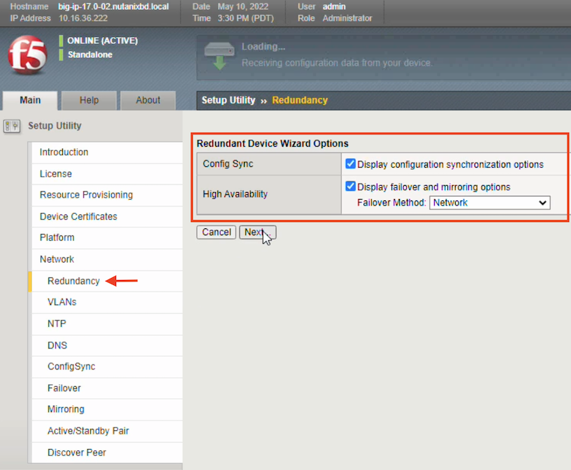
Click Next.
On the blade, repeat the previous steps for configuring the Internal Network configuration for the FIRST BIG-IP (1), like the following example:
Click Next.
On the blade, repeat the previous steps for configuring the External Network configuration for the FIRST BIG-IP (1), like the following example:
Click Next.
On the Network -> VLANs blade, repeat the previous steps for configuring the High Availability Network configuration for the FIRST BIG-IP (1), like the following example:
On the blade, in the Address text box, enter the address for the NTP server used, click Add to add it to the Time Server List, and then click Next.
On the blade, accept the default Local Address (for example, 10.16.48.192 (internal)) value, and then click Next.
On the blade, accept all default values, and then click Next.
On the blade, accept all default values, and then click Next.
Click Finished.
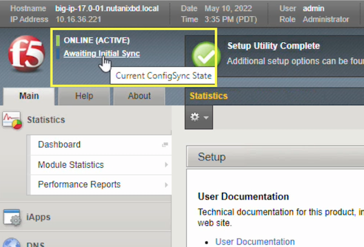
In the top-left corner, to see the current ConfigSync state, click the Awaiting Initial Sync link.
Complete the HA connectivity
To verify the device certificate, open the browser tab for the FIRST BIG-IP (1), click Device Certificate Matches, and then complete the following:
- Device Name - leave default values
- Sync Failover Group Name - leave default values
Click Add Device.
The Setup Utility Home page appears. On both browser pages for BIG-IP 1 and BIG-IP 2, in the top-left corner, to see the current ConfigSync state, click the Awaiting Initial Sync link.
In the left menu, select the option, click Sync, and then in the top-left corner, wait for an In Sync message to appear.
Create an address pool and add members
The following steps demonstrates this process using Nutanix AOS 5.20. For updated steps, see the AOS 6.5 Nutanix documentation.
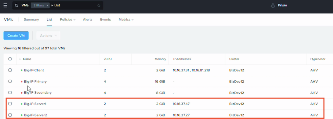
In the Nutanix AHV console in the F5-filtered list of VMs, note the IP Addresses of the two BIG-IP VMs (for example, server-1 and server-2).
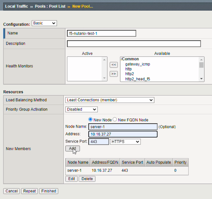
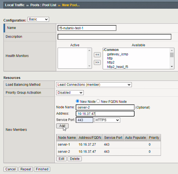
In the F5 BIG-IP Setup utility, in left menu click , in the far-right side of the window click Create, and then do the following:
In the Configuration pane, in the Name text box, enter/select the name of your BIG-IP VM.
In the Resources pane, complete the following:
- Load balancing method - select Least Connections (member)
- Priority Group Activation - select Disabled
- New node - select to enable
- Node Name - select server-1
- Address - enter the IP address of the first server in the filtered list of VMs in Nutanix
- Server port - enter 443 and select HTTPS
Click Add.
Repeat these steps selecting Node Name - enter server-2 and the Address - enter the IP address for the first server in the filtered list of VMs in Nutanix, and then click Finished.
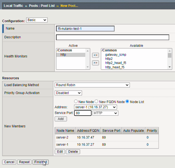
On the menu, do the following:
Click Create, and then complete the following:
- Name - select the pool you just created
- Health monitor - select HTTP
- Load Balancing Method - select Round Robin
- Priority Group Activation - select Disabled
- New Members - select the Node list option
- Address - select Server-2, HTTP, and Service Port 80
Click Add, expand Address, select Server-1, select HTTP, Service Port 80, click Add again, and then Finished.
In the F5 BIG-IP Setup utility, in left menu click blade, in the far-right side of the window, click Create, and then in the General Properties pane do the following:
- Name - enter a name associating it with the pool you just created (for example, select the pool name appending “VS”, identifying virtual server).
- Type - select standard
- Destination Address/Mask - select Host, and then enter an IP address
- Service Port - select Port, 443, and HTTPS
- Notify Status to Virtual Address - select to enable option
In the Configuration - Basic pane, do the following:
- HTTP Profile (Client) - select http
- HTTP Profile (server) - select http
- SSL Profile (server) - select the clientssl option from the Available list
- Source Address Translation - select Auto Map
In the Resources pane, expand the Default Pool drop-down list and select the pool you just created.
Click Finished.
Sync configuration across device groups and test the connection
- To sync the changes, click the Virtual Server in the list, in the top-right corner, click the Change Pending link, and then, in the Device Group menu click Sync. The status message will change to In Sync.
- To test, open a new browser window in privacy mode, enter an external IP address for the BIG-IP devices, and then refresh the browser.
See Also