F5 Application Delivery Controller Solutions > F5 AppWorld Lab - TMOS Architecture Source | Edit on
Lab 1: The Basics (Networking, Pools and Virtual Servers)
In this lab we will access the Management Graphical User Interface (GUI). We will then create the VLANs, and assign self IP addresses to our VLAN. As mentioned during our lecture portion, BIG-IPs may be put in-line or one-armed depending on your customer’s requirements and topology.
- Log on to the bigip01 TMUI (GUI) Interface:
UDF - Under Components, select the Access drop-down and then TMUI
Creating VLANs
First, you will need to log into bigip01. You will need create two untagged VLANs, one client-side VLAN (client_vlan) and one server-side VLAN (server_vlan) for the devices in your network.
From the sidebar select Network >> VLANs then select Create

Under General Properties:
Name: client_vlan
The name is for management purposes only, you could name them after your children or pets
Tag: <leave blank>
Entering a tag is only required for “Tagged” (802.1q) interfaces, “Untagged” interfaces will automatically get a tag which is used for internal L2 segmentation of traffic.
Under Resources in the Interfaces section:
Interface: 1.1
Tagging: Untagged
Select the Add button. Leave all other items at the default setting.

When you have completed your VLAN configuration, hit the Finished button
Important
Now create another untagged VLAN named server_vlan on interface 1.2, following the same steps as above.
When you are done, you should have two untagged VLANs, one on interface 1.1 and one on interface 1.2.

Creating Self IPs
Go to Network >> Self IPs, select Create.

Create a new Self IP, for the server_vlan and client_vlan VLANs. In Network >> Self IPs >> New Self IP, under Configuration enter:
Option
Server-side
Client-side
Name
server_ip
client_ip
IP Address
10.1.20.245
10.1.10.245
Netmask
255.255.255.0
255.255.255.0
VLAN
server_vlan
client_vlan
Port Lockdown
Allow None
Allow None
Caution
A common mistake is to forget to change the VLAN/Tunnel selection to the appropriate VLAN. Make sure your Self IPs are in the appropriate VLAN.
The default Port Lockdown setting of Allow None means the Self IP only responds to ICMP requests.
- The Allow Defaults selection opens the following on the Self IP of the VLAN.
TCP: ssh, domain, snmp, https
TCP: 4353, 6699 (for F5 protocols, such as HA and iQuery)
UDP: 520, cap, domain, f5-iquery, snmp
PROTOCOL: ospf
When you have completed your Self IP configuration, hit the Finished button. You should have something similar to the following:

Assigning the Default Gateway
Go to Network >> Routes and then Add.
Here is where we assign our default gateway (and other static routes as desired)
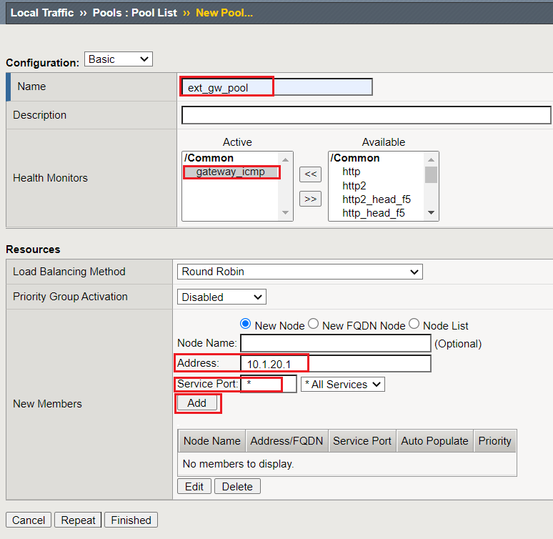
Under Properties
Name: def_gw
Destination: 0.0.0.0
Netmask: 0.0.0.0
Resource: Use Gateway…
Gateway Address: 10.1.10.1
When you have completed defining your default gateway, hit the Finished button
Verify your network configuration
Use SSH or WebShell (UDF Only) to access your BIG-IP.
Ping your default gateway, 10.1.10.1
Ping a web server at 10.1.20.11.
Creating Pools
In this lab we will build a pool and virtual server to support our web site and verify our configurations by accessing our web servers through the BIG-IP. Verification will be performed visually and through various statistical interfaces.
From the sidebar select Local Traffic >> Pools then select Create. Here we will create our new pool
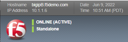
Under Configuration:
Name: www_pool (The name is for management purposes only, no spaces can be used)
Description: <optional>
Health Monitor: http
Under Resources
Load Balancing Method: <leave at the default Round Robin>
Priority Group Activation: <leave at default>
New Members:
Address
Service Port
10.1.20.11
80
10.1.20.12
80
10.1.20.13
80
As you enter each IP address and port combination hit Add button
When you have completed your pool configuration, hit the Finished button
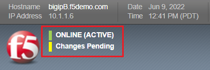
Creating Virtual Servers
Under Local Traffic select Virtual Servers then select Create.
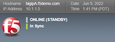
Under General Properties
Name: www_vs
Description: <optional>
Type: Standard
Source/Address: <leave blank>
Note
The default is 0.0.0.0/0, all source IP address are allowed
Destination Address/Mask: 10.1.10.100
Note
The default mask is /32
Service Port: 80 or HTTP
Under Configurations
The web servers do not use the BIG-IP LTM as the default gateway. This means return traffic will route around the BIG-IP LTM and the TCP handshake will fail. To prevent this we can configure SNAT Automap on the Virtual Server. This will translate the client IP to the Self IP of the egress VLAN and ensure the response returns to the BIG-IP.
Source Address Translation: Auto Map
Under Resources
iRules: none
Policies: none
Default Pool: From the drop down menu, select the pool (www_pool) which you created earlier
Default Persistence Profile: None
Fallback Persistence Profile: None
When you have completed your virtual server configuration, hit the Finished button
You have now created a Virtual Server
Note
Items in the GUI that are blue are links i.e., shortcuts
Now let’s see if our virtual server works!
UDF - log into your Ubuntu Jumpbox via xRDP access method using the credentials provided in Documentation section
Open the browser from the bottom of the screen, go to the Virtual Server you just created http://10.1.10.100
Refresh the browser screen several times (use “<ctrl>” F5)
Go to your BIG-IP and view the statistics for the www_vs virtual server and the www_pool pool and its associated members
Go to Statistics >> Module Statistics >> Local Traffic
Choose Virtual Servers from "Statistics Type" drop-down menu

or, Go to Local Traffic >> Virtual Servers >> Statistics
Go to Local Traffic >> Pools >> Statistics to see pool member statistics
Did each pool member receive the same number of connections?
Did each pool member receive approximately the same number of bytes?
Note the Source and Destination address when you go to directly and through the virtual server
Let’s archive our configuration in case we have to fall back later.
Go to System >> Archives and select Create.
Name your archive lab1_the_basics_net_pool_vs
Extra Credit!
You can also review statistics via the CLI, simply SSH to the management IP of your BIG-IP. Refer to your Student Information page and Network Diagram for the IP address.
Check out the Linux CLI and TMSH
Review the information of the following command:
export TERM=vt100; bigtop –n
Type q to quit.
Take a look at the TMOS CLI, type “tmsh” to enter the Traffic Management Shell
(tmos)# show ltm pool
(tmos)# show ltm pool detail
show statistics from all pools
(tmos)# show ltm virtual
(tmos)# show ltm virtual detail
Show statistics of all virtual servers
Check out the Dashboard!
Go to Statistics >> Dashboard

This will take you to the BIG-IP Dashboard page. The F5 BIG-IP Dashboard in the Configuration utility provides real-time, customizable graphical views of system performance, including CPU usage, memory, network traffic (PPS, Mbps), and connection statistics. It allows users to create custom "view sets" combining data from various modules (LTM, DNS, AFM) to monitor application health and traffic flow.

Feel free to explore the dashboard and create your own view sets to monitor the performance of your virtual server and pool!