F5 Application Delivery Controller Solutions > Intro to F5OS : Migrating from iSeries Source | Edit on
Exercise 1: Initial Setup
In this lab, you will use the F5OS user interfaces to perform initial platform configuration and setup tasks, then configure new tenants. If you have no partner, complete all sections. If you are partnered up, follow section A or section B.
When done with your respective section, review the changes made in the other section to see each configuration element.
If you prefer CLI configuration to the GUI, ssh into the rSeries instead of using the GUI and follow those instructions below.
Student A Section
UI Option - See below for CLI
Log into the webUI of the rSeries appliance at: https://10.193.5.10+X
Navigate to System Settings -> General
Set the Hostname to r5900-X.aw26.lab where X is your station number - Note : Allowed characters are lowercase alphanumeric characters (a-z, 0-9) and hyphens (-)
Configure a Login Banner such as "Welcome to Appworld 2026"
Configure a MOTD Banner such as "Hello from r5900-X"
Click the Save button at the bottom right of the page
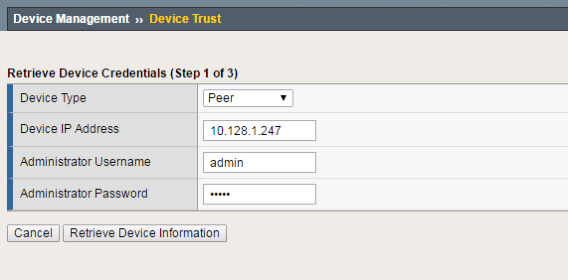
Click OK on the General Properties dialog box.
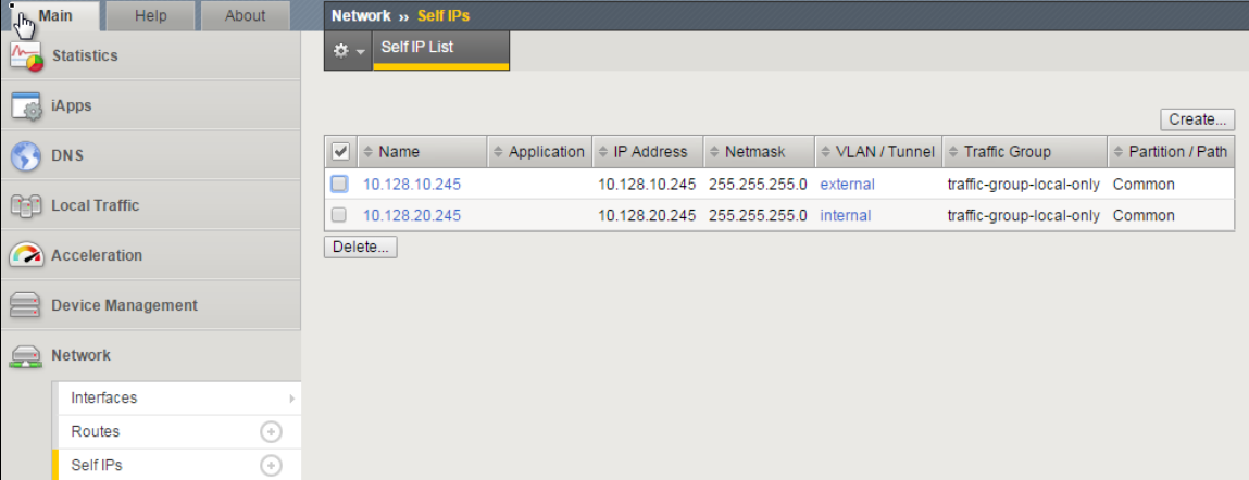
You will be logged out of the UI and have to re-login. Your browser may prompt to reconnect to the BIG-IP since changing the hostname updated the self-signed management certificate CLI from config mode
appliance-1# config
appliance-1(config)# system config hostname r5900-<X>.aw26.lab
appliance-1(config)# system config login-banner "Welcome to Appworld 2026"
appliance-1(config)# system config motd-banner "You have logged into r5900-<X>.1"
appliance-1(config)# commit
Commit complete.
r5900-1(config)# exit
Next change the default timeouts (note Token is minutes, CLI Idle is seconds)
Navigate Authentication & Access -> Authentication Settings
Set Token Lifetime to 60 minutes
Save your change, Click Save button at the bottom right of the page
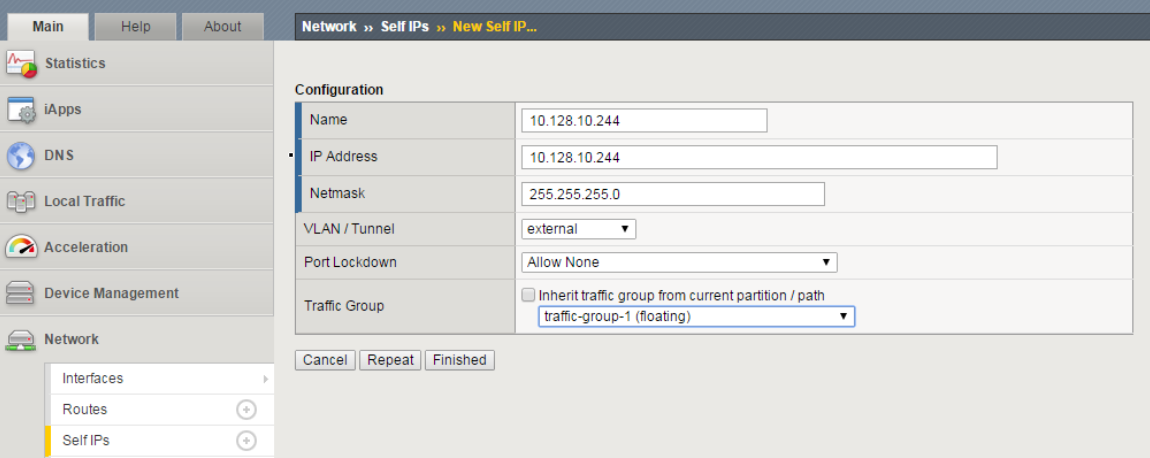
Navigate to System Settings -> System Security
Set CLI Idle Timeout to 1200 seconds (at the bottom of the page)
Click Save button at the bottom right of the page
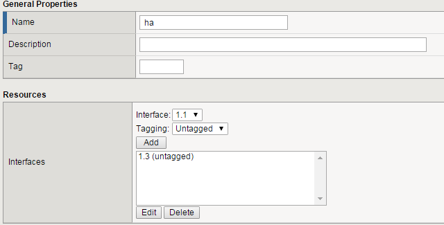
CLI commands
r5900-1# config
r5900-1(config)# system aaa restconf-token config lifetime 60
r5900-1(config)# system settings config idle-timeout 1200
r5900-1(config)# commit
Commit complete.
r5900-1(config)# exit
Exercise 1: Networking
The Default port group speeds are 100G (port 1 & 2) and 25G (ports 3-10). In this lab ports 3 through 6 have already been configured for 10G.
Note: Changing the Port Group configuration from default will require a reboot of the appliance to load a new FPGA bitstream. In practice, be sure to complete all Port Group modifications at the same time to avoid multiple reboots.
To validate this: navigate to Dashboard -> Network which displays a layout of current network port speeds and port status:
Dashboard
CLI commands
r5900-1# show port-mappings port-mapping
r5900-1# show running-config portgroups portgroup config mode
Next, we will validate that the Ports used in the Lab (port 3 & 4) are set to 10G
Navigate to Network Settings -> Port Groups
Verify that ports 3 & 4 are set to 10GbE
Select port 1 using the drop down and note the Port Group Mode settings
Select port 10 using the drop down and note the port group Mode settings
The r5900 has two 40/100G ports and 8 10/25G ports
Ports 1 & 2 support 100G, 40G, or 4 x 10G
Ports 3 – 10 support 10G or 25G
CLI show commands
r5900-1# show port-mappings port-mapping
r5900-1# show running-config portgroups portgroup config mode
Next, we will add a VLAN into F5OS. The internal VLAN is numbered 10+X
Navigate to Network Settings -> VLANs
Click Add to add the internal VLAN
Click Save & Close
CLI from config mode
r5900-1(config)# config
r5900-1(config)# vlans vlan (10+X) config vlan-id (10+X) name internal

     example: vlans vlan 11 config vlan-id 11 name internal
r5900-1(config-vlan-11)# commit
r5900-1(config-vlan-11)# exit
With the internal VLAN created, we now add it to the LAG
Navigate to Network Settings -> LAGs
Select Add
Create the “LAG_20G “ LAG
Select VLAN 11 and interface 3.0
Enable LACP and select LACP Interval Fast
Click Save & Close
CLI from config mode
r5900-1(config)# interfaces interface LAG_20G aggregation switched-vlan config trunk-vlans [ <10+X> ]
r5900-1(config-interface-LAG_20G)# exit
5900-1(config)# lacp interfaces interface LAG_20G
r5900-1(config-interface-LAG_20G)# config interval FAST
r5900-1(config-interface-LAG_20G)# config lacp-mode ACTIVE
r5900-1(config-interface-LAG_20G)# exit
r5900-1(config)# interfaces interface 3.0
r5900-1(config-interface-3.0)# ethernet config aggregate-id LAG_20G
r5900-1(config-interface-3.0)# exit
r5900-11(config-interface-3.0)# !
r5900-11(config-interface-3.0)# commit
Next, we will configure LLDP on Port 3
Navigate to Network Settings -> LLDP Configuration
Configure the System Name “r5900-X”
Configure LLDP on interface 3.0, by selecting it using the check box.
This will automatically enable LLDP on port 3
Review the TLV map to understand what will be sent and what is configurable for the LLDP advertisement
Save the changes
CLI from config mode
r5900-1(config)# lldp config enabled
r5900-1(config)# lldp config system-name r5900-<X>
r5900-1(config)# lldp interfaces interface 3.0
r5900-1(config-interface-3.0)# exit
r5900-1(config)# !
r5900-1(config)# commit
r5900-1(config)# exit
At this point, layer 1 should be up between the F5OS and the upstream switch. In the GUI, explore the following Network Settings tabs: LAGs, LACP Details, and LLDP Details. Network Details gives a table summary of all network interfaces.
CLI Show commands
r5900-1# show interfaces interface 3.0
r5900-1# show interfaces interface LAG_20G
r5900-1# show lacp interfaces interface LAG_20G
r5900-1# show lacp interfaces interface LAG_20G state
r5900-1# show lacp interfaces interface LAG_20G members
r5900-1# show lacp interfaces interface LAG_20G members | tab
r5900-1# show lldp state
r5900-1# show lldp interfaces interface state
r5900-1# show lldp interfaces interface neighbors
Next, we will investigate the Local Password Policy
Navigate to Authentication & Access -> Authentication Settings and click on the Show button for Local Password Policy. Here you can see the default password policy settings for users that is a strong default position, however options exist to align with organization standards for longer minimum passwords, change differential and required characters.
CLI show commands
r5900-1# show running-config system aaa password-policy
system aaa password-policy config min-length 6
system aaa password-policy config required-numeric 0
system aaa password-policy config required-uppercase 0
system aaa password-policy config required-lowercase 0
system aaa password-policy config required-special 0
system aaa password-policy config max-letter-repeat 3
system aaa password-policy config max-sequence-repeat 0
system aaa password-policy config max-class-repeat 0
system aaa password-policy config required-differences 8
system aaa password-policy config reject-username false
system aaa password-policy config apply-to-root true
system aaa password-policy config retries 3
system aaa password-policy config max-login-failures 10
system aaa password-policy config unlock-time 60
system aaa password-policy config root-lockout true
system aaa password-policy config root-unlock-time 60
system aaa password-policy config max-age 0
Finally, we look at the TLS policy for the F5OS GUI interface. Changes here could be required based on corporate security or NIST recommendations. Navigate to System Settings -> System Security, and note the httpd Cipher Suites text box:
To update these settings, edit or paste in the suite types separated by a colon and save changes. For example, the following cipher list would remove any non ECC ciper suite. Note: changing the suite will restart HTTPS services
ECDHE-RSA-AES256-GCM-SHA384:ECDHE-ECDSA-AES256-GCM-SHA384:ECDHE-RSA-AES256-SHA384:ECDHE-ECDSA-AES256-SHA384:ECDHE-RSA-AES256-SHA:ECDHE-ECDSA-AES256-SHA:ECDH-RSA-AES256-GCM-SHA384:ECDH-ECDSA-AES256-GCM-SHA384:ECDH-RSA-AES256-SHA384:ECDH-ECDSA-AES256-SHA384:ECDH-RSA-AES256-SHA:ECDH-ECDSA-AES256-SHA:ECDHE-RSA-AES128-GCM-SHA256:ECDHE-ECDSA-AES128-GCM-SHA256:ECDHE-RSA-AES128-SHA256:ECDHE-ECDSA-AES128-SHA256:ECDHE-RSA-AES128-SHA:ECDHE-ECDSA-AES128-SHA:ECDH-RSA-AES128-GCM-SHA256:ECDH-ECDSA-AES128-GCM-SHA256:ECDH-RSA-AES128-SHA256:ECDH-ECDSA-AES128-SHA256:ECDH-RSA-AES128-SHA:ECDH-ECDSA-AES128-SHA
CLI from config mode
r5900-1(config)# system security services service httpd config ssl-ciphersuite ECDHE-RSA-AES256-GCM-SHA384:ECDHE-ECDSA-AES256-GCM-SHA384:ECDHE-RSA-AES256-SHA384:ECDHE-ECDSA-AES256-SHA384:ECDHE-RSA-AES256-SHA:ECDHE-ECDSA-AES256-SHA:ECDH-RSA-AES256-GCM-SHA384:ECDH-ECDSA-AES256-GCM-SHA384:ECDH-RSA-AES256-SHA384:ECDH-ECDSA-AES256-SHA384:ECDH-RSA-AES256-SHA:ECDH-ECDSA-AES256-SHA:ECDHE-RSA-AES128-GCM-SHA256:ECDHE-ECDSA-AES128-GCM-SHA256:ECDHE-RSA-AES128-SHA256:ECDHE-ECDSA-AES128-SHA256:ECDHE-RSA-AES128-SHA:ECDHE-ECDSA-AES128-SHA:ECDH-RSA-AES128-GCM-SHA256:ECDH-ECDSA-AES128-GCM-SHA256:ECDH-RSA-AES128-SHA256:ECDH-ECDSA-AES128-SHA256:ECDH-RSA-AES128-SHA:ECDH-ECDSA-AES128-SHA
r5900-1(config)# commit
//End of Exercise 1 (Student A)
Student B Section
UI Option - See below for CLI
Log into the webUI of the rSeries appliance at: https://10.193.5.10+X
Navigate to Network Settings -> VLANs
Click Add to add the external then the internal vlans
CLI from config mode
r5900-1(config)# vlans vlan (30+X) config vlan-id (30+X) name external
r5900-1(config-vlan-31)# exit
Navigate to Network Settings -> LAGs and click the Add button - Configure LAG_20G as shown below - Click Save And Close button at the bottom right of the page
CLI from config mode
r5900-1(config)# interfaces interface LAG_20G config type ieee8023adLag
r5900-1(config-interface-LAG_20G)# aggregation config lag-type LACP
r5900-1(config-interface-LAG_20G)# aggregation switched-vlan config trunk-vlans [ <30+X> ]
r5900-1(config-interface-LAG_20G)# exit
r5900-1(config)# interfaces interface 4.0 ethernet config aggregate-id LAG_20G
r5900-1(config-interface-4.0)# exit
r5900-1(config)# lacp interfaces interface LAG_20G config interval FAST lacp-mode ACTIVE
r5900-1(config-interface-LAG_20G)# exit
r5900-1(config)#commit
Next, we will configure DNS
Navigate to System Settings -> DNS
Click Add under DNS Lookup Servers, and add 8.8.8.8 and 8.8.4.4
Save your changes

CLI from config mode
r5900-1# config
r5900-1(config)# system dns servers server 8.8.8.8
r5900-1(config)# system dns servers server 8.8.4.4
r5900-1(config-server-8.8.4.4)# commit
r5900-1(config-server-8.8.4.4)# exit
r5900-1(config)# exit
Navigate to System Settings -> Time Settings Click Add under NTP Servers, and add time.nist.gov Save your changes
CLI from config mode
r5900-1(config)# system ntp servers server time.nist.gov
r5900-1(config-server-time.nist.gov)# exit
r5900-1(config-community-appworld)# exit
Navigate to System Settings -> SNMP Configuration Under Add under Communities, and add a community
CLI from config mode
r5900-1(config)# system snmp communities community appworld config security-model [ v2c ]
After configuring an SNMP community, an additional step is needed to enable SNMP polling. By default, F5OS enables an implicit firewall on the management interface that restricts access to certain ports, and port 161 is blocked.
The Allowed IP Addresses feature under System Settings -> System Security provides the mechanism to add additional ports/protocols as well as lock down existing services. Refer to this knowledge article https://my.f5.com/manage/s/article/K000134482 for more details and some general guidelines. The next step is to allow SNMP access for the lab environment.
Note: Use care setting port to All: if a typo is made in the allow list (and there is not another matching allow list), the policy could lock access out requiring a console login to re-configure.
Navigate to System Settings -> System Security Click Add under Allowed IP Addresses, and add the following Save your changes

CLI from config mode
r5900-1(config)# system allowed-ips allowed-ip snmp_allow config ipv4 address 10.193.5.0 prefix-length 24 port 161
r5900-1(config-allowed-ip-snmp_allow)# exit
r5900-1(config)#
Additional system security settings include cipher suite configuration for HTTP and SSH services. To update the sshd key exchange algorithms, paste in the updated list enclosed by [ ] brackets.
The following string removes Diffie Hellman key exchange algorithms. Replace the existing string in the text box and save the changes.
[ curve25519-sha256 curve25519-sha256@libssh.org ecdh-sha2-nistp256 ecdh-sha2-nistp384 ecdh-sha2-nistp521 ]
CLI from config mode
r5900-1(config)# system security services service sshd config kexalgorithms [ curve25519-sha256 curve25519-sha256@libssh.org ecdh-sha2-nistp256 ecdh-sha2-nistp384 ecdh-sha2-nistp521 ]
r5900-1(config)# !
r5900-1(config)# commit
The following warnings were generated:
'system security services service sshd': Changing SSH configuration will restart the SSHD service.
Proceed? [yes,no] yes
Navigate to Network Settings -> LLDP Configuration
Ensure that LLDP is Enabled, the system name is the r5900-X
Ensure LLDP on interface 3.0 is enabled (should have been done by Student A)
Configure LLDP on interface 4.0, by selecting it using the check box.
This will automatically enable LLDP on port 4
Review the TLV map to understand what will be sent and what is configurable for the LLDP advertisement
Save the changes
CLI from config mode
r5900-1(config)# lldp config enabled
r5900-1(config)# lldp interfaces interface 4.0
r5900-1(config-interface-4.0)# exit
r5900-1(config)# commit
r5900-1(config)# exit
At this point, layer 1 should be up between the F5OS and the upstream switch. In the GUI, explore the following Network Settings tabs: LAGs, LACP Details, and LLDP Details.
Network Details gives a table summary of all network interfaces.
CLI show commands
r5900-1# show interfaces interface 4.0
r5900-1# show interfaces interface LAG_20G
r5900-1# show lacp interfaces interface LAG_20G
r5900-1# show lacp interfaces interface LAG_20G state
r5900-1# show lacp interfaces interface LAG_20G members
r5900-1# show lacp interfaces interface LAG_20G members | tab
r5900-1# show lldp state
r5900-1# show lldp interfaces interface state
r5900-1# show lldp interfaces interface neighbors
Navigate to Authentication & Access -> Authentication Settings and click on the Show button for Local Password Policy. Here you can see the default password policy settings for users that is a strong default position, however options exist to align with organization standards for longer minimum passwords, change differential and required characters.
CLI from config mode
r5900-1# show running-config system aaa password-policy
system aaa password-policy config min-length 6
system aaa password-policy config required-numeric 0
system aaa password-policy config required-uppercase 0
system aaa password-policy config required-lowercase 0
system aaa password-policy config required-special 0
system aaa password-policy config max-letter-repeat 3
system aaa password-policy config max-sequence-repeat 0
system aaa password-policy config max-class-repeat 0
system aaa password-policy config required-differences 8
system aaa password-policy config reject-username false
system aaa password-policy config apply-to-root true
system aaa password-policy config retries 3
system aaa password-policy config max-login-failures 10
system aaa password-policy config unlock-time 60
system aaa password-policy config root-lockout true
system aaa password-policy config root-unlock-time 60
system aaa password-policy config max-age 0
//End of Exercise 1 (Student B)