Deploy F5 BIG-IP Virtual Edition with Azure Gateway Load Balancer
F5® BIG-IP® Virtual Edition (VE) delivers a wide range of application and security services, aggregating your application portfolio under a single platform.
Microsoft’s Gateway Load Balancer (GWLB) is a SKU of the Azure Load Balancer portfolio designed for high performance and high availability scenarios with third-party Network Virtual Appliances (NVAs). With the capabilities of Gateway Load Balancer, you can easily deploy, scale, and manage NVAs. Chaining a Gateway Load Balancer to your public endpoint only requires one click.
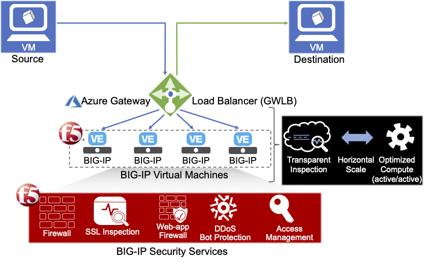
The F5 BIG-IP VE and Azure GWLB integration enables the industry leading BIG-IP security services with the following benefits:
- Simplified connectivity - Leverage Azure native networking constructs to ‘insert’ BIG-IP security services in different traffic flows.
- Public scalability - Scale your deployment based on your actual usage. Horizontally scale your BIG-IP VEs.
When to use GWLB?
F5 BIG-IP VE delivers a wide-range of application and security services. Depending on the service and other requirements the BIG-IP VEs are typically deployed in one of two modes: Network mode or Proxy mode.
Note
Azure GWLB is only applicable today with Network deployment mode. First, you identify which deployment mode is relevant for you.
- Option 1 – Network (GWLB Supported):
- Common use cases include Network firewall, DDoS protection, and Transparent WAF.
- Flow transparency is maintained (no source or destination NAT).
- Directing traffic to the BIG-IP VEs is done using routing by the network, making sure traffic goes back to the same BIG-IP VE in order to maintain traffic symmetry is also based on routing.
- Option 2 – Proxy (not GWLB-supported)
- Providing ingress services to the application (WAF, LB, L7 DDoS, and Bot protection), services are applied to an application specific virtual server on the BIG-IP VE.
- The BIG-IP VE source NAT (SNAT) manages the traffic to ensure that the return traffic arrives at the same BIG-IP VE; thus, maintaining traffic symmetry.
- Directing user’s traffic to the BIG-IP’s is done using DNS. A FQDN will map to a specific virtual server on the BIG-IP VE.
GWLB Architecture
The following diagram illustrates a BIG-IP VE multi-NIC deployment in GWLB:
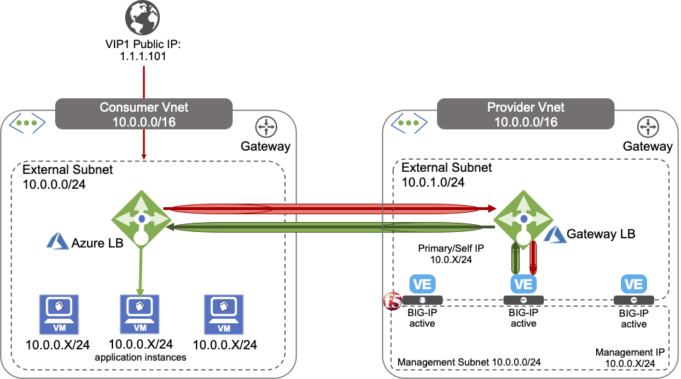
The previous diagram illustrates an example deployment of multiple standalone 2-NIC BIG-IP VEs (consult the BIG-IP VE Multi-NIC deployment guide).
In the previous diagram, the BIG-IP VE tier sits in the Provider Virtual Network and the application sits in the Consumer Virtual Network. Client traffic flows in the following sequence:
- Consumer Load Balancer
- Provider Azure Gateway Load Balancer
- BIG-IP Security Tier
- Provider Azure Gateway Load Balancer
- Consumer Load Balancer
- Application Tier
This Provider VNET containing the BIG-IP Virtual Machines contain two subnets:
- An external, public subnet, where you will create a virtual service(s) to accept tunneled application traffic
- A management subnet, where you can access the BIG-IP Configuration utility, which you use to configure BIG-IP VE.
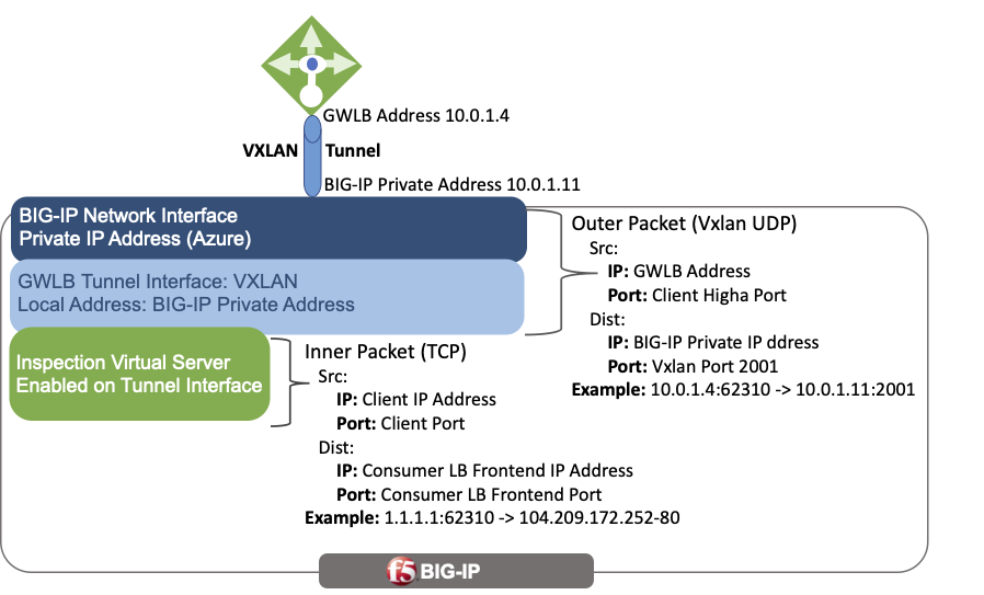
The previous diagram illustrates high-level overview of packet decapsulation from the Azure Gateway Load Balancer.
Disclaimer:
- This guide does not include deploying the consumer portion or all the components a production environment may require.
- Use the following, individual parameters and values provided to create the previous example deployment and to customize according to your needs.
Accessing the BIG-IP VE
This guide demonstrates deploying one of the 2-NIC BIG-IP virtual machines in BIG-IP Tier illustrated in the previous diagram.
Important
Restrict access to the BIG-IP Management UI (GUI and SSH) to trusted sources/networks only; for example, using Bastion Host/Bastion Service/Jumpbox, or other similar service.
For example:
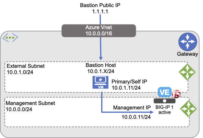
Deploying an appropriate access solution is outside the scope. See your cloud provider’s documentation for instructions on selecting and deploying an appropriate access solution. However, for simplicity and evaluation purposes only, the following steps describe provisioning a public IP address access to the Management UI.
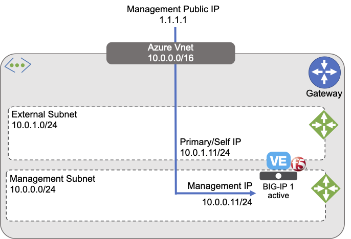
The previous diagram illustrates an evaluation-only deployment of a standalone BIG-IP VE with two NICs, one for Management and one for Application traffic.
Deployment guide
The following sections outline steps to take for deploying a BIG-IP VE Multi-NIC with Azure GWLB. To create a multi-NIC deployment, you must first create an Azure Virtual Network with more than one subnet. Use this the network environment to host your virtual machines.
Prerequisites
OPTIONAL: Create an SSH key pair. In Azure, you can configure a username and password to access the BIG-IP VE. However, as SSH access is the more common pattern among clouds, this guide uses the ssh key method.
Create an Azure Resource Group to deploy the Virtual Network and BIG-IP VE.
Create a Virtual Network with multiple subnets with at least two subnets, a management subnet for administrative access, and an external subnet for application access. For example:
- Management subnet: 10.0.0.0/24
- External subnet: 10.0.1.0/24
Important
Management Access should always be restricted to trusted resources and networks, accessed from Bastion or Jump Boxes, or other similar service. For illustration and evaluation purposes, this guide also includes instructions to create Public IPs to provide temporary access the Management Interface; however, Production deployments MUST never provide such access.
Create security groups to determine which traffic can travel in and out of the Virtual Network:
- Management traffic group
- External traffic group for virtual server traffic
Create SSH key pair
Optional: To access the Azure virtual machines, you will leverage an SSH key. You can create Azure SSH keys or provide a public key if you already have one. Later, if you use Windows, then use an SSH tool like PuTTY to access your Azure instance. You may have to use PuTTYgen to convert the .pem file to .ppk format.
Create resource groups
To create a resource group to contain your Azure virtual network and BIG-IP virtual machines, do one of the following (for complete steps, see Azure documentation):
In the Azure portal, navigate to .
Select your Subscription.
For .
Select .
Create resource groups using the Azure CLI type:
az group create --name example-rg -l eastus
Create a Virtual Network with multiple subnets
A BIG-IP VE instance must be in an Azure virtual network. Use the Azure Portal to create a virtual network with the desired number of subnets. At a minimum, create management and external subnets. For complete details, see Azure documentation.
In the Azure Portal, navigate to .
Select the IP Addresses tab, update the default network CIDR, and then click the Add Subnet to add the additional subnets using the following example information:
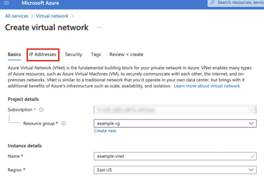
Type Name CIDR Virtual Network Example-vnet 10.0.0.0/16 subnet Management 10.0.0.0/24 subnet External 10.0.1.0/16 Note
The example in the following screenshot a modified default network address space,
10.0.0.0/16to match the previous diagram.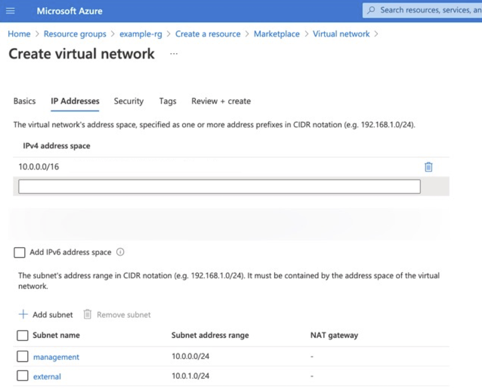
To create virtual subnets using the Azure CLI, type:
az network vnet create --name example-vnet -g example-rg -l eastus --address-prefixes 10.0.0.0/16
az network vnet subnet create --name management -g example-rg --vnet-name example-vnet  --address-prefixes 10.0.0.0/24
az network vnet subnet create --name external -g example-rg --vnet-name example-vnet --address-prefixes 10.0.1.0/24
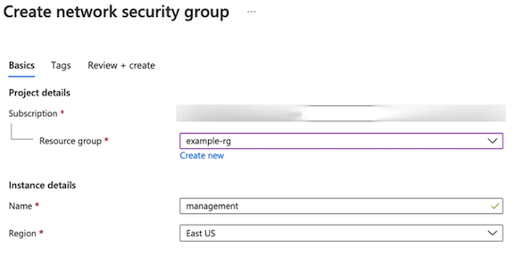
Create security groups
Create Network Security Groups to control the inbound and outbound traffic allowed by the Virtual Machine (see Azure documentation for complete details). You can create security groups based on your needs. This specific configuration uses three security groups for the following:
- The BIG-IP Management UI
- Virtual server traffic
- Internal traffic
Create three groups with inbound security rules based on the following information. Leave outbound traffic for each group as the default (all).
Purpose Name Type Protocol Source Management management-nsg SSH and HTTPS 22 and 443 Administrator’s IP address on a secure network. Tunnel Traffic external-nsg UDP 2000 and 2001 All GWLB external-nsg ICMP Any All GWLB Health Probe external-nsg TCP 24500 All Clustering external-nsg UDP, TCP and TCP 1026, 4353, and 6123-6128 OPTIONAL: For Internal traffic restricted to intra-vnet and/or inter-BIG-IP communication, for example 10.0.0.0/16. BIG-IP VE usesUDP 1026for Failover Heartbeats,TCP 4353for Config Sync and TCP 6123-6128 for ASM Policy Sync. For more information, see K13946.In Azure Portal, navigate to .
Select the management security group just created in Step 2, and then select Inbound Security Rules.
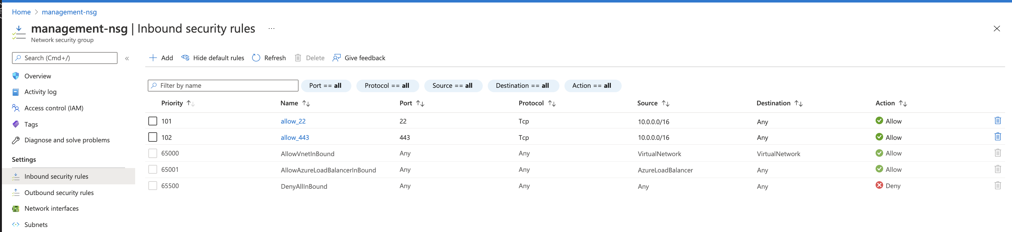
Repeat the previous steps for the external security groups using the rules outlined in the previous table.
Click Save.
To create network security groups using the Azure CLI, type:
# Management Security Group
az network nsg create --name management-nsg -g example-rg -l eastus
az network nsg rule create --name allow_22  -g example-rg --nsg-name management-nsg --priority 101 --access Allow --description 'allow port 22' --destination-port-ranges 22 --protocol Tcp --source-address-prefixes "<YOUR-CLIENT-NETWORK>"
az network nsg rule create --name allow_443 -g example-rg --nsg-name management-nsg --priority 102 --access Allow --description 'allow port 443' --destination-port-ranges 443 --protocol Tcp --source-address-prefixes "<YOUR-CLIENT-NETWORK>"
# External Security Group
az network nsg create --name external-nsg -g example-rg -l eastus
# Gateway Traffic
az network nsg rule create --name allow-2001-udp -g example-rg --nsg-name external-nsg --priority 101 --access Allow --description 'allow vxlan on udp port 2001' --destination-port-ranges 2001 --protocol Udp --source-address-prefixes "*"
az network nsg rule create --name allow-2002-udp -g example-rg  --nsg-name external-nsg --priority 102 --access Allow --description 'allow vxlan on udp port 2002' --destination-port-ranges 2002 --protocol Udp --source-address-prefixes "*"
az network nsg rule create --name allow-24500-tcp -g example-rg  --nsg-name external-nsg --priority 103 --access Allow --description 'allow gw health probe on tcp port 24500' --destination-port-ranges 24500 --protocol Tcp --source-address-prefixes "*"
az network nsg rule create --name allow-icmp -g example-rg  --nsg-name external-nsg --priority 104 --access Allow --description 'allow gw icmp' --destination-port-ranges "*" --protocol ICMP --source-address-prefixes "*"
# Clustering
az network nsg rule create --name allow_failover  -g example-rg --nsg-name internal-nsg --priority 101 --access Allow --description 'allow udp port 1026' --destination-port-ranges 1026 --protocol Udp --source-address-prefixes "10.0.0.0/16"
az network nsg rule create --name allow_config_sync -g example-rg  --nsg-name internal-nsg --priority 102 --access Allow --description 'allow tcp port 4353' --destination-port-ranges 4353 --protocol Tcp --source-address-prefixes "10.0.0.0/16"
az network nsg rule create --name allow_config_sync_asm  -g example-rg --nsg-name internal-nsg --priority 103 --access Allow --description 'allow tcp port 6123-6128' --destination-port-ranges '6123-6128' --protocol Tcp --source-address-prefixes "10.0.0.0/16"
Create BIG-IP Virtual Machine
To deploy the BIG-IP VE virtual machine, do the following:
- Create additional network interfaces: External interface:
10.0.1.11 - Deploy the BIG-IP VE instance. Create BIG-IP Virtual machine with two NICS:
- Management NIC
- External NIC
Create additional network interfaces
By default, when deploying the BIG-IP virtual machine through the Azure Portal, it creates one NIC. To create a multiple-NIC BIG-IP, you must create additional NICs and attach them to the BIG-IP VE after initial creation.
However, through automation (through the Azure CLI, Terraform, ARM templates), you can create virtual machines with multiple NICs without the need for stopping and restarting (see the following inline Azure CLI examples).
Note
For multi-tenant, multi-service deployments, F5 recommends leveraging static IPs in order to help recreate Azure network configurations that match network configurations in your BIG-IP UCSs (BIG-IP’s backup files).
For complete details, see Azure documentation.
In the Azure Portal, navigate to .
Create the external NIC, using the following information:
Textbox Value Resource Group example-rg Name external-nic Region East US Virtual network example-vnet subnet external (10.0.1.0/24) Private IP address assignment Static Private IP address 10.0.1.11 Security groups external-sg 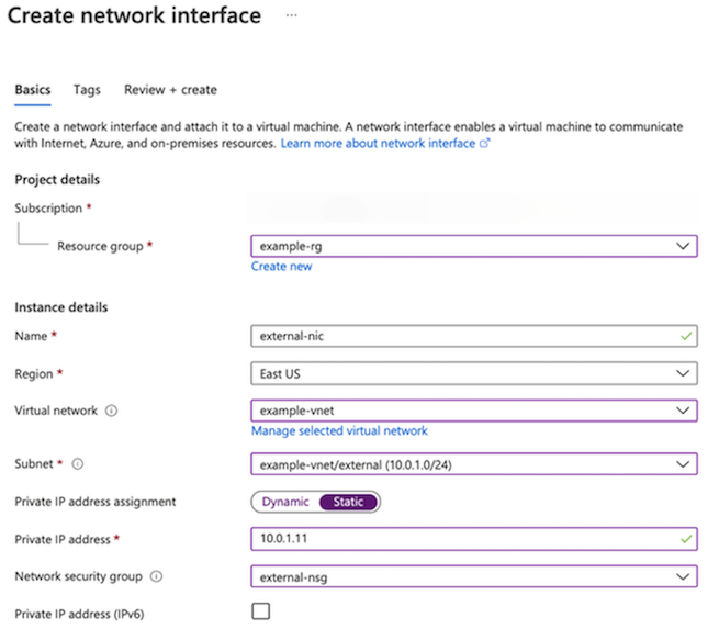
At the prompt, click Next: Tags or Create.
To create network interfaces using the Azure CLI, type:
# External NIC
az network nic create  --name external-nic -g example-rg --vnet-name example-vnet --subnet external --ip-forwarding --private-ip-address 10.0.1.11 --network-security-group external-nsg
Note
If deploying through the CLI, you can also create the management NIC.
# Management NIC
az network nic create --name management-nic -g example-rg  --vnet-name example-vnet --subnet management  --ip-forwarding --network-security-group management-nsg  --private-ip-address 10.0.0.11
If accessing management interface using a Public IP, do the following:
Create a public IP:
# Public IP
az network public-ip create --name management-public-ip -g example-rg --allocation-method Static
Create the NIC with public IP attached:
# Management NIC
az network nic create --name management-nic -g example-rg  --vnet-name example-vnet --subnet management  --ip-forwarding --network-security-group management-nsg  --private-ip-address 10.0.0.11 --public-ip-address management-public-ip
Deploy a BIG-IP VE virtual machine
For complete details, see Azure documentation.
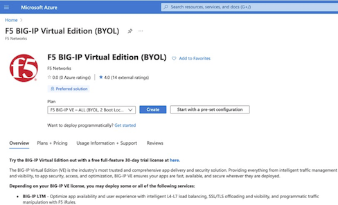
To create a virtual machine of BIG-IP VE, you deploy a version of it from the Azure Marketplace.
Visit the Azure Marketplace.
Search for, “F5 BIG-IP”.
Select the offering you want to deploy, and then click Get It Now.
Complete the Account Information, and then click Continue.
Click Create.
On Configure Virtual Machine Settings menu, complete the following information accordingly:
- Select the Resource Group previously created.
- Enter the Virtual Machine Name.
- Select the Region.
- Select the appropriate Size (for example, a select an option with at least 2 cores, 8 GB of memory like DS3_v2). See the BIG-IP VE Support Matrix for more information.
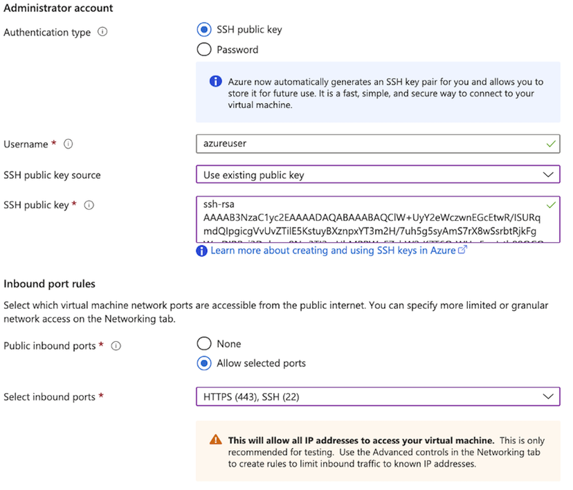
For Authentication Type, select SSH, and complete the following information:
Textbox Value Username Enter username. For SSH public key source Select Use existing public key option (see previous requirements). For SSH public key source Enter your SSH Public Key. Public Inbound Ports Select Allow Selected Ports, and enter SSH (22) and HTTPS (443) 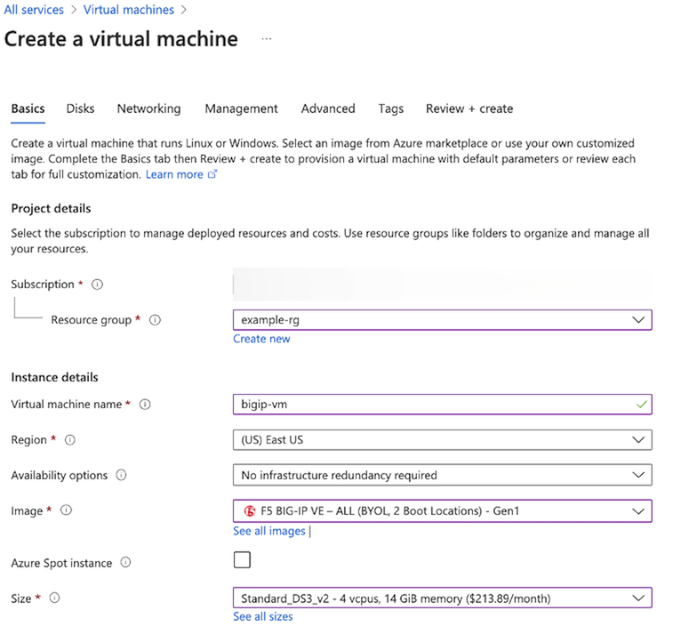
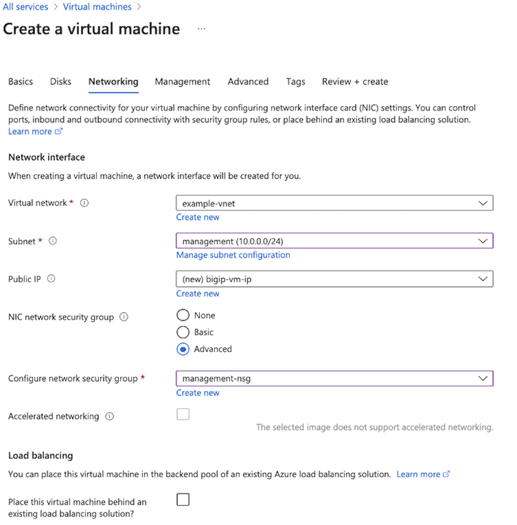
Select the Networking tab and complete the following:
- Expand the Virtual Network list, select your Virtual Network.
- Expand the Subnet list, select the management subnet: 10.0.0.0/24.
- In the NIC network security group, select the Advanced option.
- In the Configure network security group list, select the management-sg security group.
Click Next on the remaining tabs and complete all information as directed.
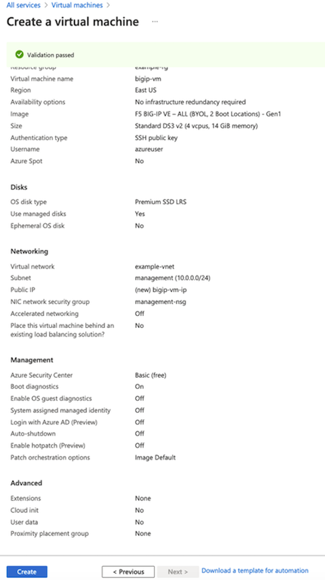
Once finished, on the Review + create page, review the summary, and then click Create.
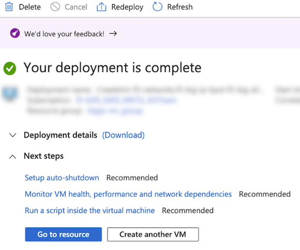
After the “Your deployment is complete” message appears, select Go to resource.
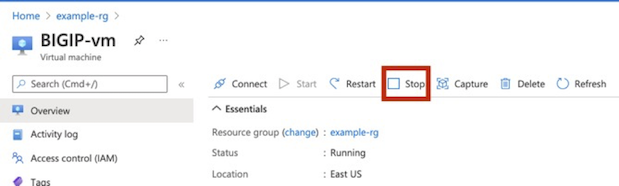
Select the Overview menu, and then select Stop.
Important
Before logging in or making any changes, you must stop the BIG-IP VE. Doing so, enables you to attach the additional NICs.
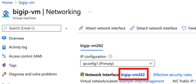
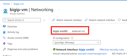
Do the following to change the Management IP to Static.
Under , select a NIC (for example, bigip-vm262).
Under , select ipconfig, and then change Assignment to Static.
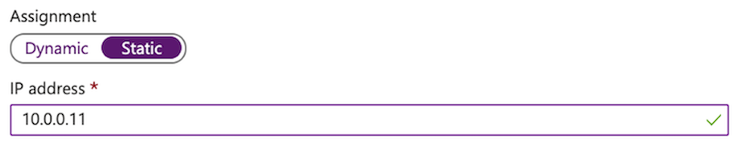
Enter the Management address: 10.0.0.11.
Click Save.
Do the following to attach the additional NICs (external-nic):
Navigate to the .
Click Attach network interface.
Select the external-nic, and then click OK.
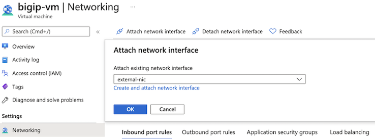
Repeat these steps for the internal-nic.
You will now see two NICs attached to the virtual machine.
Re-start the virtual machine.
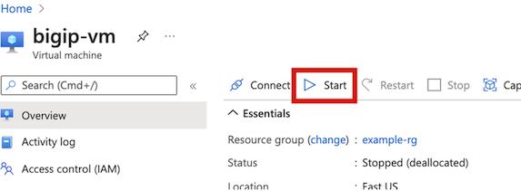
Once the virtual machine Status displays, “Running,” log into the Management IP.
To deploy the BIG-IP VE using the Azure CLI and substituting your own public SSH Key for “—ssh-key-values”, type:
az vm create --name BIGIP-vm -g example-rg  \
 --image f5-networks:f5-big-ip-best:f5-bigip-virtual-edition-25m-best-hourly:16.0.101000  \
 --size Standard_DS3_v2 \
 --nics management-nic external-nic \
 --admin-username azureuser \
 --ssh-key-values "ssh-rsa AAAAB3NzaC1yc2EAAAADAQABAAABAQClW+UyY2eWczwnEGcEtwR/ISURqmdQIpgicgVvUvZTilXY…."
Create an Azure Gateway Load Balancer
Do the following to create the Azure Gateway Load Balancer:
Create Azure Gateway Load Balancer
Consult the Azure documentation for complete information.
In the Azure portal, navigate to .

Enter a Name (for example, example-gwlb).
Select .
Click .
Click Create.
To create an Azure Gateway Load Balancer using the Azure CLI, type:
az network lb create --name example-gwlb --sku Gateway -g example-rg --vnet-name example-vnet --subnet external --frontend-ip-name example-gwlb-frontend-ip --backend-pool-name example-backend-pool
Create a Backend Pool
Provide the values according to the table below. The Ports and IDs are used in the example deployment. However, you can use any valid ports or IDs that match values used the Network Security Groups and BIG-IP configurations.
| Name | Value | Description |
|---|---|---|
| Name | example-backend-pool | The name of your backend pool. |
| Virtual Network | example-vnet | The provider virtual network. |
| Internal Port | 2002 | The UDP port on which BIG-IP will accept internal tunnel traffic. |
| Internal Identifier | 802 | The ID used to identify the internal VLAN. |
| External Port | 2001 | The UDP port on which BIG-IP will accept external tunnel traffic. |
| External Identifier | 801 | The ID used to identify the internal VLAN. |
Consult the Azure documentation for complete information.
Enter a Name like, example-backend-pool.
In the Virtual Network text box, select example-vnet.
In the Type text box, select Internal and External.`
In the Internal Port text box, enter 2002.
In the Internal Identifier text box, enter 802.
In the External Port text box, enter 2001.
In the External Identifier text box, enter 801.
Select Virtual Machines, in the filter by name text box, enter bigip-vm, and then select your BIG-IP virtual machine from the list.
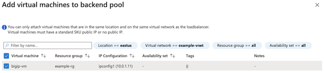
Select Next: Inbound rules.
To create back end pool using the Azure CLI, type:
az network lb address-pool tunnel-interface add -g example-rg --lb-name example-gwlb --address-pool example-backend-pool --type external --protocol vxlan --identifier 801 --port 2001
az network lb address-pool tunnel-interface update -g example-rg --lb-name example-gwlb --address-pool example-backend-pool --index 0 --type internal --protocol vxlan --identifier 802 --port 2002
# Add BIG-IP to Backend Pool
az network lb address-pool address add -n bigip-vm-address --ip-address 10.0.1.11  -g example-rg --lb-name example-gwlb --pool-name example-backend-pool --vnet example-vnet
Create Inbound Rules and Health Monitor
Consult the Azure documentation for complete information.
- Click Add a Load balancing rule.
- Enter a Name like, type example-lb-rule.
- In the Protocol text box, enter All.
- In the Port text box, enter 0.
- In the Backend Port, enter 0.
- Select Health Probe, click Create New.
- Enter a Name like, example-health-probe.
- In the Protocol, select HTTP.
- In the Port, enter 24500 (must match the Security Groups and BIG-IP Configuration).
- Click OK.
- In the Backend Pool, select example-backend-pool.
- Click Next: Outbound Rule, click Next: Tags, and then click Review: Create.
To create back end pool using the Azure CLI, type:
az network lb probe create --name example-health-probe -g example-rg --lb-name example-gwlb --protocol http --port 24500 --path /healthcheck
az network lb rule create --name example-lb-rule  -g example-rg --lb-name example-gwlb --protocol all --frontend-port 0 --backend-port 0 --frontend-ip-name example-gwlb-frontend-ip --backend-pool-name example-backend-pool --probe-name example-health-probe --disable-outbound-snat true
Configure BIG-IP VE
Depending on how you have configured access to the Management port, you will now login and configure BIG-IP VE so that traffic passes through it to your application servers.
- Set the admin password for BIG-IP VE. Before you can license and provision BIG-IP VE, use SSH and your key pair to
connect to the instance and set a strong password. In
tmsh, typemodify auth password admin. - License BIG-IP VE. Use the admin account to log in to the BIG-IP Configuration utility (
https://<MANAGEMENT-IP>). If you have trouble accessing the Configuration utility, check the Azure security groups to ensure that they allow the appropriate traffic. - Provision BIG-IP VE. Enable the modules you need.
- Create external VLAN. These VLANs and their interfaces directly correspond to the Azure external vlan and their interfaces.
- external VLAN interface: 1.1
- Create self IP. These static IP addresses provide a way for application traffic to reach the BIG-IP system.
These addresses should match the private IP addresses you assigned to the external subnets in Azure.
- External self IP: 10.0.1.11
- Create VXLAN Profiles:
- gwlb-ext-vxlan-prof
- gwlb-int-vxlan-prof
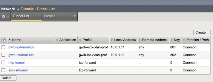
- Create VXLAN Tunnels:
- gwlb-external-tun
- gwlb-internal-tun
- Create VXLAN Groups:
- vg-1
- vg-2
- Create Self-IPs for tunnels:
- External Tunnel Self IP: 192.168.1.11/28
- Internal Tunnel Self IP: 192.168.2.11/28
- Create static L2 entries. Similar to how Self-IPs bind a network to vlans, these static entries will bind tunnels to their layer 2.
- Create a Virtual Server for the GWLB Health Probe. This provides the upstream Gateway a system level health view for the BIG-IPs.
- Create application VIPs to listen for tunnel traffice. The virtual server(s) provide a destination for
your inbound web traffic from the tunnel Virtual IP:
- 0.0.0.0:80
- 0.0.0.0:443
Set the admin password for BIG-IP VE
When you first boot BIG-IP VE, you must connect to the instance and create a strong admin password. You will use the admin account and password to access the BIG-IP Configuration utility. If the management interface can access the Internet, ensure the password is secure.
Connect to BIG-IP VE using one of the following options:
From a Jumpbox or similar service that has access to your management network, at the command prompt, navigate to the folder where you saved your ssh key and type:
ssh -i <YOUR-PRIVATE-KEY> azureuser@<MANAGEMENT-IP>If you have configured a public IP, type:
ssh -i <YOUR-PRIVATE-KEY> azureuser@<MANAGEMENT-PUBLIC-IP>Open PuTTy and do the following:
In the Host Name (or IP address) text box, enter the external IP address, for example:
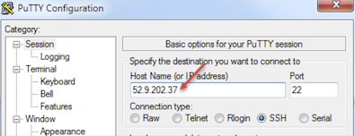
In the Category pane, click .
In the Private key file for authentication text box, choose your .ppk file.
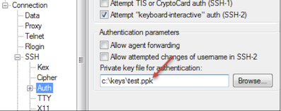
Click Open, if a host key warning appears, click OK, at the terminal login screen, type:
azureuser, and then press Enter.
You are auto-logged into TMSH (Traffic Management Shell). To change to the shell, type:
bash.Modify the admin password, type:
modify auth password azureuser.At the New Password prompt, enter the new password, and then press Enter.
At the Confirm password prompt, re-enter the password, and then press Enter.
To ensure that the system saves the changes, type:
save sys config, and then press Enter. You will see the following message:Saving Ethernet mapping...done.
License BIG-IP VE
Important
In the following procedure, where you see admin, substitute with azureuser.
You must enter license information before you can use BIG-IP VE.
Open a web browser and log in to the BIG-IP Configuration utility by using
httpswith the external IP address, for example:https://<external-ip-address>. The username isadminand the password is the one you set previously.On the Setup Utility Welcome page, click Next.
On the General Properties page, click Activate.
In the Base Registration key field, enter the case-sensitive registration key from F5.
For Activation Method, if you have a production or Eval license, choose Automatic and click Next.
If you chose Manual, complete these steps:
In the Step 1: Dossier field, copy all of the text and then click Click here to access F5 Licensing Server.
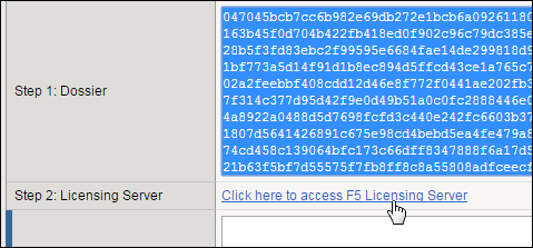
A separate web page opens.
On the new page, click Activate License.
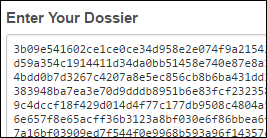
In the Enter your dossier field, paste the text and click Next.
Accept the agreement and click Next.
On the Activate F5 Product page, copy the license text in the box. Now go back to the BIG-IP Configuration utility and paste the text into the Step 3: License field.
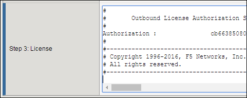
Click Next.
The BIG-IP VE system registers the license and logs you out. When the configuration change is successful, click Continue to provision BIG-IP VE.
Provision BIG-IP VE
You must confirm the modules you want to run before you can begin to work in the BIG-IP Configuration utility.
Open a web browser and log in to the BIG-IP Configuration utility.
On the Resource Provisioning screen, change settings if necessary and click Next.
On the Device Certificates menu, click Next.
On the Platform menu, in the Host Name text box, and then click Next.
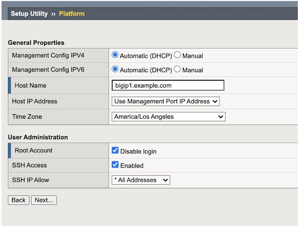
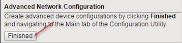
On the Network menu, click Finished.
Create external VLANs
In BIG-IP VE, you must create an external VLAN that corresponds to the Azure VPC subnets.
In the BIG-IP VE Configuration utility, on the Setup Utility Network menu, under Advanced Network Configuration, click Finished.
On the Main tab, navigate to .
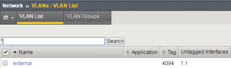
Click Create and complete the following information for the external VLAN.
Text box Value :guilabel:Name external Interface 1.1 Tagging: Untagged MTU 9001 Click Finished.
The screen refreshes, and the new VLAN is in the list.
To create an external VLAN in BIG-IP CLI, type:
tmsh create net vlan external interfaces add { 1.1 } mtu 9001
Create self IP
Before starting these steps, in Azure, note the primary private IP addresses for the external network interface (device index 1).
In the BIG-IP VE Configuration utility, on the Main tab, select .
Click Create and complete the appropriate information for the external-self IP address.
Text box Value Name external-self IP Address 10.0.1.11 Netmask 255.255.255.0 VLAN/Tunnel external Port Lockdown Allow All Click Finished.
The screen refreshes, and the new self IP address is in the list.
To create a self IP in BIG-IP CLI, type:
tmsh create net self external-self address 10.0.1.11/24 vlan external allow-service all
Create VXLAN Profiles
In the BIG-IP VE Configuration utility, on the Main tab, select .
Click Create and complete the following information for the external Tunnel, selecting Custom to access the Port and Flooding Type settings.
Text box Value Name gwlb-ext-vxlan-prof Parent Profile vxlan Port 2001 Flooding Type None 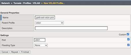
Click Repeat and complete the following information for the internal Tunnel, selecting Custom to access the Port and Flooding Type settings:
Text box Value Name gwlb-int-vxlan-prof Parent Profile vxlann Port 2002 Flooding Type None Click Finished.
To create VXLAN Profiles using BIG-IP CLI, type:
tmsh create net tunnels vxlan gwlb-ext-vxlan-prof port 2001 flooding-type none
tmsh create net tunnels vxlan gwlb-int-vxlan-prof port 2002 flooding-type none
Create VXLAN Tunnels
In the BIG-IP VE Configuration utility, on the Main tab, click .
Click Create and complete the appropriate information for the external Tunnel:
Text box Value Name qwlb-external-tun Key 801 Profile gwlb-ext-vxlan-prof Local Address 10.0.1.11 Secondary Address Any MTU 1450 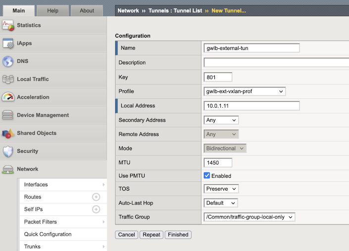
Click Repeat and complete the appropriate information for the internal Tunnel:
Text box Value Name qwlb-external-tun Key 801 Profile gwlb-ext-vxlan-prof Local Address 10.0.1.11 Secondary Address Any MTU 1450 Click Finished.
To create VXLAN tunnels in BIG-IP CLI, type:
tmsh create net tunnels tunnel gwlb-external-tun key 801 profile gwlb-ext-vxlan-prof local-address 10.0.1.11 remote-address any mtu 1450
tmsh create net tunnels tunnel gwlb-internal-tun key 802 profile gwlb-int-vxlan-prof local-address 10.0.1.11 remote-address any mtu 1450
Create VXLAN Groups
In the BIG-IP VE Configuration utility, select the Main tab, click , and then click Create.
Complete the following information to create the external vlan group:
Text box Value Name vg-1 Vlans gwlb-external-tunnel Local Address 10.0.1.11 Bridge All Traffic enabled 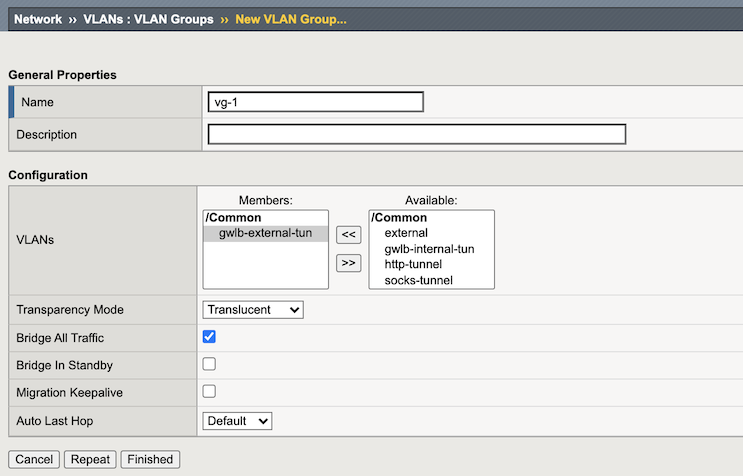
Click Repeat, complete the following information to create the internal vlan group:
Text box Value Name vg-2 Vlans gwlb-external-tunnel Local Address 10.0.1.11 Bridge All Traffic enabled
To create VXLAN groups in BIG-IP CLI, type:
tmsh create net vlan-group vg-1 members add { gwlb-external-tun } bridge-traffic enabled
tmsh create net vlan-group vg-2 members add { gwlb-internal-tun } bridge-traffic enabled
Create Self-IPs for Tunnels
In the BIG-IP VE Configuration utility, on the Main tab, click , and then click Create.
Complete the following information to create a Self-IP for the external VXLAN tunnel:
Text box Value Name vxlan-external-self IP Address 192.168.1.11 Netmask 255.255.255.240 Port Lockdown Allow All 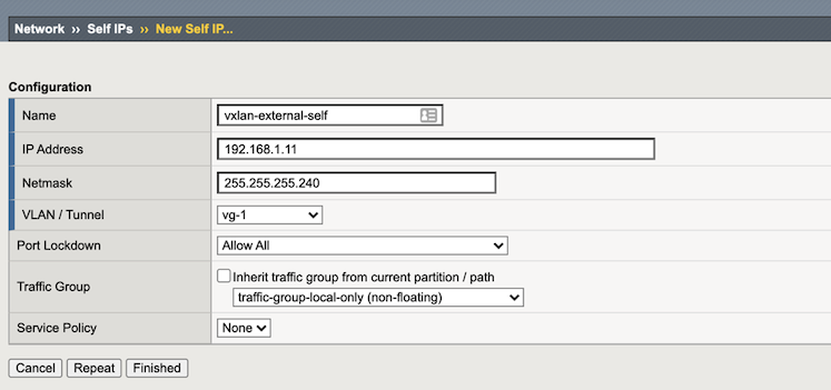
Click Repeat and compelte the following informaiton to create a Self-IP for the internal VXLAN tunnel:
Text box Value Name vxlan-external-self IP Address 192.168.2.11 Netmask 255.255.255.240 Port Lockdown Allow All Click Finished.
To create Self-IP for tunnels in BIG-IP CLI, type:
tmsh create net self vxlan-external-self address 192.168.1.11/28 vlan vg-1 allow-service all
tmsh create net self vxlan-internal-self address 192.168.2.11/28 vlan vg-2 allow-service all
Create Static L2 entries
Create static ARP entry that forwards traffic to GWLB.
Select , and then click Create.
Text box Value Description Name gwlb-int-vxlan-prof IP Address 192.168.1.1 Must match the Virtual Service on the Tunnel’s Pool Member. Mac Address ff:ff:ff:ff:ff:aa Arbitrary value 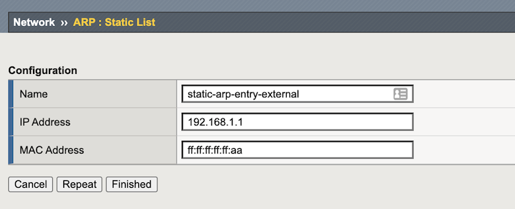
Click Repeat and complete the following information for the internal Tunnel:
Text box Value Description Name gwlb-int-vxlan-prof IP Address 192.168.2.1 Must match the Virtual Service on the Tunnel’s Pool Member. Mac Address ff:ff:ff:ff:ff:aa Arbitrary value Click Finished.
To create FDB entry for external/internal BIG-IP VXLAN tunnel that points to GWLB, on the Main tab select , and then select External tunnel (gwlb-external-tunnel) option.
Select Tunnel Static Forwarding Table, and then click Create.
Text box Value Description Mac Address 12:34:56:78:9a:bc Must match GWLB mac address. This can vary depending upon your environment. To obtain, see the following TMSH CLI example. Endpoint 10.0.1.4 The Gateway IP address Description GWLB 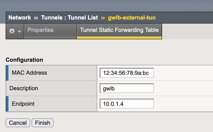
Click Finished.
To create a FDB entry for the internal VXLAN tunnel, on the Main tab, select , and then click the external tunnel (gwlb-internal-tunnel) option.
Click the Tunnel Static Forwarding Table, and then Create.
Complete the following information:
Text box Value Description Mac Address ff:ff:ff:ff:ff:bb Must match static ARP entry on Internal Tunnel. Endpoint 10.0.1.4 The Gateway IP address Description GWLB Click Finished.
To create Static L2 entries in BIG-IP CLI, type:
tmsh create net arp static-arp-entry-external ip-address 192.168.1.1 mac-address ff:ff:ff:ff:ff:aa
tmsh create net arp static-arp-entry-internal ip-address 192.168.2.1 mac-address ff:ff:ff:ff:ff:bb
tmsh modify net fdb tunnel gwlb-external-tun records add { 12:34:56:78:9a:bc { description gwlb endpoint 10.0.1.4 } }
tmsh modify net fdb tunnel gwlb-internal-tun records add { ff:ff:ff:ff:ff:bb { description gwlb endpoint 10.0.1.4 } }
# Example
GATEWAY_ADDRESS="10.0.1.4"
GATEWAY_MAC=$(arping -I external -c 1 $GATEWAY_ADDRESS | egrep -o '([[:xdigit:]]{1,2}:){5}[[:xdigit:]]{1,2}')
tmsh modify net fdb tunnel gwlb-external-tun records add { $GATEWAY_MAC { description gwlb endpoint $GATEWAY_ADDRESS } }
tmsh modify net fdb tunnel gwlb-internal-tun records add { $GATEWAY_MAC { description gwlb endpoint $GATEWAY_ADDRESS } }
Create Virtual Service for GWLB Health Probe
Create a VIP that responds to the Gateway Loadbalancer’s Health Probe. This virtualThe Virtual’s port must match the port used by the Health Monitor. The previous examples use TCP 24500.
In the BIG-IP VE Configuration utility, on the Main tab, click , and then click Create.
In the Name text box enter
http-server.In the Definition, enter the following:
when HTTP_REQUEST {
   HTTP::respond 200 'System Responding'
}
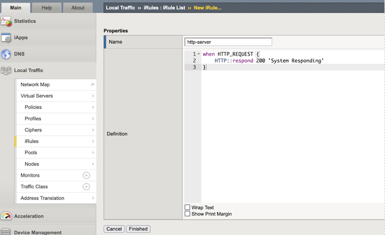
Click Finished.
To create the Virtual Service, in the BIG-IP VE Configuration utility, on the Main tab, select , and then click create.
Complete the following information:
Text box Value Description Name gwlb-health-probe-vs Name of Virtual Server Destination Address/Mask 10.0.1.11 Must match the Self-IP and Private Address of the External NIC Service Port 24500 Arbitrary value that must match what is configured on the GWLB Health Probe Port and Security Groups. HTTP Profile (Client) http A http profile must be applied for an http iRule. iRules http-server Select the iRule previously entered. 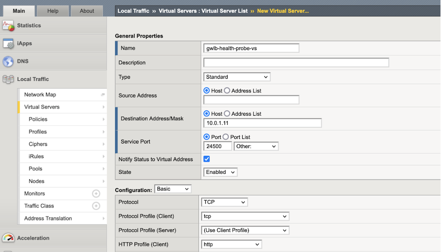
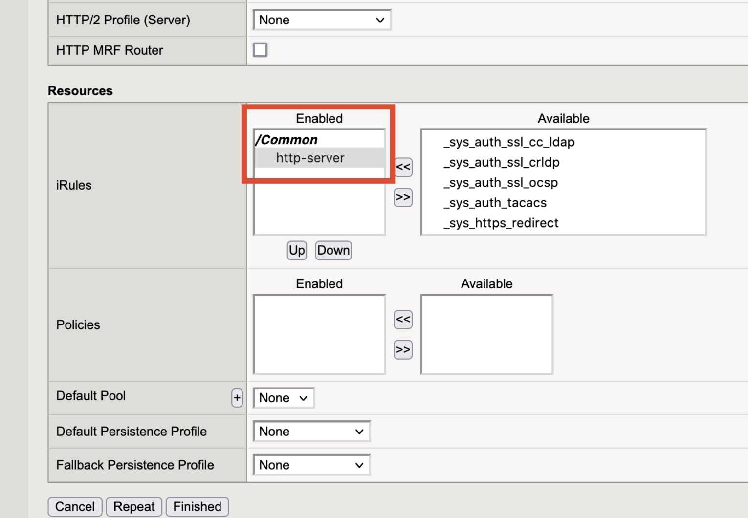
To create Virtual Service for GWLB Health Probe using the BIG-IP CLI, type:
# Create Virtual Service to answer GWLB Health Probe
tmsh create ltm rule /Common/http-server when HTTP_REQUEST { HTTP::respond 200 \'System Responding\'}
tmsh create ltm virtual gwlb-health-probe-vs destination 0.0.0.0:24500 mask 0.0.0.0 ip-protocol tcp profiles add { http tcp } vlans-enabled vlans add { external } rules { http-server }
Create Application VIPs to listen for tunnel traffic
Disclaimer: The following virtual servers are used to illustrate passing traffic. Customize according to your use case (for example, adding security policies, F5 BIG-IP Advanced WAF policies, leverages F5® BIG-IP® Telemetry Streaming streaming to send Azure log analytics, Insights, or similar data).
The required component settings for this solution include:
- Disable Address and Port Translation.
- Enable Address and Port Translation on the tunnels.
- Forward traffic through the tunnels using the pools with tunnel destinations.
Create a pool for tunnel traffic arriving on the external tunnel
Traffic goes through BIG-IP VE to a pool. The pool member will be a tunnel endpoint, so traffic is forwarded through the tunnel.
Click the Main tab, and select .
Click Create.
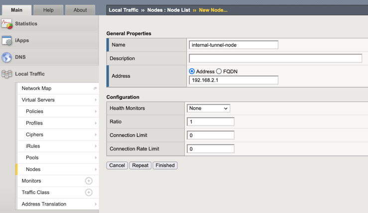
In the Name text box, enter
internal-tunnel-node.In the Address text box, enter
192.168.2.1.In the Health Monitor text box, select
None.Traffic goes through BIG-IP VE to a pool. The pool member will be a tunnel endpoint, so traffic is forwarded through the tunnel.
Click the Main tab, select .
Click Create.
In the Name text box, enter
internal-tunnel-pool.In the New Members section, select the
internal-tunnel-nodepreviously created.In the Service Port, select Select All Services.
Click Add. The list now contains the member.
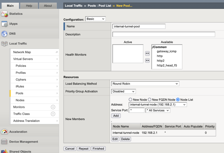
Click Finished.
To create Application VIPs using the BIG-IP CLI, type:
tmsh create ltm node internal-tunnel-node address 192.168.2.1 monitor none
tmsh create ltm pool internal-tunnel-pool members add { internal-tunnel-node:0 } monitor none
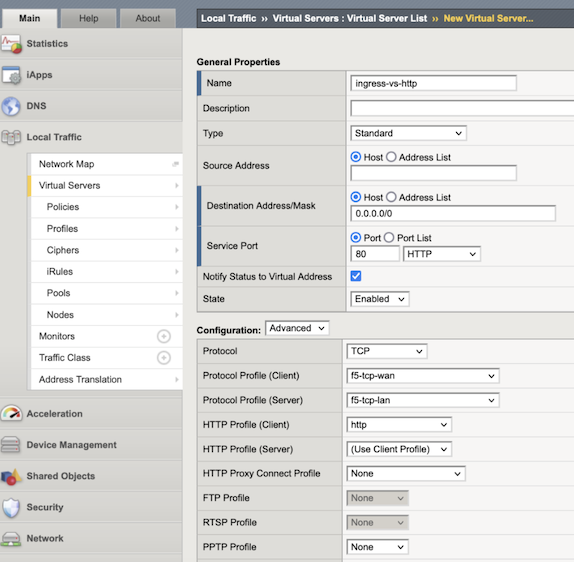
Create a Virtual Server(s) for incoming tunnel traffic
You must create a virtual server for traffic arriving on the external tunnel. Application traffic is forwarded through the internal tunnel.
In the BIG-IP Configuration utility, click the Main tab, select .
Click Create,and click .
Complete the following information:
Text box Value Description Name ingress-vs-http Destination Address/Mask 0.0.0.0/0 Service Port 80 Enter a port number or a service name from the Service Port list that matches your Consumer LB port. TCP Profile (clientside) f5-tcp-wan TCP Profile (serverside) f5-tcp-lan HTTP Profile http Vlans gwlb-external-tun Source Address Translation None Address Translation Disabled Port Translation Disabled Default Pool internal-tunnel-pool Configure any other settings as needed, and then click Finished.
To create VIPs for incoming tunnel traffic using the BIG-IP CLI, type:
tmsh create ltm virtual ingress-vs-http destination 0.0.0.0:80 mask any ip-protocol tcp profiles add { f5-tcp-wan { context clientside } f5-tcp-lan { context serverside } http } vlans-enabled vlans add { gwlb-external-tun } translate-address disabled source-port preserve-strict pool internal-tunnel-pool
Create Virtual Server(s) for outgoing tunnel traffic
Optionally, you can create a virtual server for outgoing traffic. Application traffic arrives on the internal tunnel and is forwarded back out through the external tunnel.
Create a Pool for outgoing tunnel traffic
- Click the Main tab, select .
- Click Create.
- In the Name text box, enter
external-tunnel-node. - In the Address text box, enter ``192.168.1.1`.
- In the Health Monitor text box, select
None. - Click the Main tab, click :menuselection:Local Traffic -> Pools`.
- Click Create.
- In the Name text box, enter
external-tunnel-pool. - In the New Members section, select the
external-tunnel-nodeyou previously created. - Set Service Port to
Select All Services. - Click Add. The list now contains the member.
To create a pool for outgoing tunnel traffic using TMSH CLI, type:
# Create Pool to process Outgoing Tunnel Traffic
tmsh create ltm node external-tunnel-node address 192.168.1.1 monitor none
tmsh create ltm pool external-tunnel-pool members add { external-tunnel-node:0 } monitor none
Create a virtual server for outgoing tunnel traffic
In the BIG-IP Configuration Utility, on the Main tab, and select .
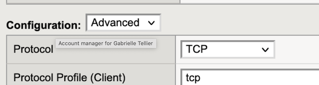
Click Create, set Configuration to
Advanced, and then complete the following information:Text box Value Description Name egress-vs-http Type Performance-Layer4 Service Port 80 Use a port number or a service name from the Service Port list that matches your Consumer LB port. Type Protocols All Profilel fastL4 Vlans (enabled) gwlb-internal-tun Source Address Translation None Address Translation Disabled Port Translation Disabled Default Pool external-tunnel-pool Configure any other settings as needed, and then click Finished.
To create a virtual server using TMSH CLI, type:
# Create Virtual Service to process Outgoing Tunnel Traffic
tmsh create ltm virtual egress-vs-http destination 0.0.0.0:80 mask any ip-protocol any vlans-enabled vlans add { gwlb-internal-tun } translate-address disabled source-port preserve-strict pool external-tunnel-pool
Repeat the previous Deploy BIG-IP Virtual Machine steps, to deploy more BIG-IPs and add them to the Gateway Load Balancer pool. F5 recommends automating this process. For example, see F5 DevCentral.
Azure CLI summary
#!/bin/bash
### CREATE RESOURCE GROUP
az group create --name example-rg -l eastus
### CREATE NETWORK AND SUBNETS
az network vnet create --name example-vnet -g example-rg -l eastus --address-prefixes 10.0.0.0/16
az network vnet subnet create --name management -g example-rg --vnet-name example-vnet  --address-prefixes 10.0.0.0/24
az network vnet subnet create --name external -g example-rg --vnet-name example-vnet --address-prefixes 10.0.1.0/24
az network vnet subnet create --name internal -g example-rg --vnet-name example-vnet --address-prefixes 10.0.2.0/24
az network vnet subnet create --name application  -g example-rg --vnet-name example-vnet --address-prefixes 10.0.3.0/24
### CREATE NETWORK SECURITY GROUPS
# Management Security Group
az network nsg create --name management-nsg -g example-rg -l eastus
az network nsg rule create --name allow-22  -g example-rg --nsg-name management-nsg --priority 101 --access Allow --description 'allow port 22' --destination-port-ranges 22 --protocol Tcp --source-address-prefixes "10.0.0.0/16"
az network nsg rule create --name allow-443 -g example-rg --nsg-name management-nsg --priority 102 --access Allow --description 'allow port 443' --destination-port-ranges 443 --protocol Tcp --source-address-prefixes "10.0.0.0/16"
# External Security Group
az network nsg create --name external-nsg -g example-rg -l eastus
# Gateway Traffic
az network nsg rule create --name allow-2000-udp -g example-rg --nsg-name external-nsg --priority 101 --access Allow --description 'allow vxlan on udp port 2000' --destination-port-ranges 2000 --protocol Udp --source-address-prefixes "*"
az network nsg rule create --name allow-2001-udp -g example-rg  --nsg-name external-nsg --priority 102 --access Allow --description 'allow vxlan on udp port 2001' --destination-port-ranges 2001 --protocol Udp --source-address-prefixes "*"
az network nsg rule create --name allow-24500 -g example-rg  --nsg-name external-nsg --priority 103 --access Allow --description 'allow gw health probe on tcp port 24500 ' --destination-port-ranges 24500 --protocol Tcp --source-address-prefixes "*"
# Clustering
az network nsg rule create --name allow-failover  -g example-rg --nsg-name internal-nsg --priority 101 --access Allow --description 'allow udp port 1026' --destination-port-ranges 1026 --protocol Udp --source-address-prefixes "10.0.0.0/16"
az network nsg rule create --name allow-config-sync -g example-rg  --nsg-name internal-nsg --priority 102 --access Allow --description 'allow tcp port 4353' --destination-port-ranges 4353 --protocol Tcp --source-address-prefixes "10.0.0.0/16"
az network nsg rule create --name allow-config-sync-asm  -g example-rg --nsg-name internal-nsg --priority 103 --access Allow --description 'allow tcp port 6123-6128' --destination-port-ranges '6123-6128' --protocol Tcp --source-address-prefixes "10.0.0.0/16"
### CREATE NICS
# Public IP
az network public-ip create --name management-public-ip -g example-rg --allocation-method Static
# Management NIC
az network nic create --name management-nic -g example-rg  --vnet-name example-vnet --subnet management  --ip-forwarding --network-security-group management-nsg  --private-ip-address 10.0.0.11 --public-ip-address management-public-ip
# External NIC
az network nic create  --name external-nic -g example-rg --vnet-name example-vnet --subnet external --ip-forwarding --private-ip-address 10.0.1.11 --network-security-group external-nsg
# Internal NIC
az network nic create --name internal-nic  -g example-rg  --vnet-name example-vnet --subnet internal --ip-forwarding --private-ip-address 10.0.2.11 --network-security-group internal-nsg
### CREATE VIRTUAL MACHINE
az vm create --name BIGIP-vm -g example-rg  \
    --image f5-networks:f5-big-ip-best:f5-bigip-virtual-edition-25m-best-hourly:16.0.101000  \
    --size Standard_DS3_v2 \
    --nics management-nic external-nic \
    --admin-username azureuser \
    --ssh-key-values "ssh-rsa AAAAB3NzaC1yc2EAAAADAQABAAABAQClW+UyY2eWczwnEGcEtwR/ISURqmdQIpgicgVvUvZTilXY…."
### CREATE GWLB
# Create GWLB
az network lb create --name example-gwlb --sku Gateway -g example-rg --vnet-name example-vnet --subnet external --frontend-ip-name example-gwlb-frontend-ip --backend-pool-name example-backend-pool
# Create Backend Pool
az network lb address-pool tunnel-interface add -g example-rg --lb-name example-gwlb --address-pool example-backend-pool --type external --protocol vxlan --identifier 801 --port 2001
az network lb address-pool tunnel-interface update -g example-rg --lb-name example-gwlb --address-pool example-backend-pool --index 0 --type internal --protocol vxlan --identifier 802 --port 2002
# Create Health Probe
az network lb probe create --name example-health-probe -g example-rg --lb-name example-gwlb --protocol http --port 24500 --path /healthcheck
# Create LB Rules
az network lb rule create --name example-lb-rule --lb-name example-gwlb -g example-rg --protocol all --frontend-port 0 --backend-port 0 --frontend-ip-name example-gwlb-frontend-ip --backend-pool-name example-backend-pool --probe-name example-health-probe --disable-outbound-snat true
# Add BIG-IP to Backend Pool
az network lb address-pool address add -n bigip-vm-address --ip-address 10.0.1.11  -g example-rg --lb-name example-gwlb --pool-name example-backend-pool --vnet example-vnet
BIG-IP TMSH CLI summary
# TMSH Commands
tmsh create net vlan external interfaces add { 1.1 } mtu 9001
tmsh create net self external-self address 10.0.1.11/24 vlan external allow-service all
# Gateway LB Specific Config
tmsh create net tunnels vxlan gwlb-ext-vxlan-prof port 2001 flooding-type none
tmsh create net tunnels vxlan gwlb-int-vxlan-prof port 2002 flooding-type none
tmsh create net tunnels tunnel gwlb-external-tun key 801 profile gwlb-ext-vxlan-prof local-address 10.0.1.11 remote-address any
tmsh create net tunnels tunnel gwlb-internal-tun key 802 profile gwlb-int-vxlan-prof local-address 10.0.1.11 remote-address any
tmsh create net vlan-group vg-1 members add { gwlb-external-tun }
tmsh create net vlan-group vg-2 members add { gwlb-internal-tun } bridge-traffic enabled
tmsh create net self vxlan-external-self address 192.168.1.11/28 vlan vg-1 allow-service all
tmsh create net self vxlan-internal-self address 192.168.2.11/28 vlan vg-2 allow-service all
tmsh create net arp static-arp-entry-external ip-address 192.168.1.1 mac-address ff:ff:ff:ff:ff:aa
tmsh create net arp static-arp-entry-internal ip-address 192.168.2.1 mac-address ff:ff:ff:ff:ff:bb
GATEWAY_ADDRESS=10.0.1.4; GATEWAY_MAC=$(arping -I external -c 1 $GATEWAY_ADDRESS | egrep -o '([[:xdigit:]]{1,2}:){5}[[:xdigit:]]{1,2}'); tmsh modify net fdb tunnel gwlb-external-tun records add { $GATEWAY_MAC { description gwlb endpoint $GATEWAY_ADDRESS } }; tmsh modify net fdb tunnel gwlb-internal-tun records add { ff:ff:ff:ff:ff:bb { description gwlb endpoint $GATEWAY_ADDRESS } }
# Create Virtual Service to answer GWLB Health Probe
tmsh create ltm rule /Common/http-server when HTTP_REQUEST { HTTP::respond 200 \'System Responding\'}
tmsh create ltm virtual gwlb-health-probe-vs destination 0.0.0.0:24500 mask 0.0.0.0 ip-protocol tcp profiles add { http tcp } vlans-enabled vlans add { external } rules { http-server }
# Create Virtual Service to process Incoming Tunnel Traffic
tmsh create ltm node internal-tunnel-node address 192.168.2.1 monitor none
tmsh create ltm pool internal-tunnel-pool members add { internal-tunnel-node:0 } monitor none
create ltm virtual ingress-vs-http destination 0.0.0.0:80 mask any ip-protocol tcp profiles add { f5-tcp-wan { context clientside } f5-tcp-lan { context serverside } http } vlans-enabled vlans add { gwlb-external-tun } translate-address disabled source-port preserve-strict pool internal-tunnel-pool
# Create Virtual Service to process Outgoing Tunnel Traffic
tmsh create ltm node external-tunnel-node address 192.168.1.1 monitor none
tmsh create ltm pool external-tunnel-pool members add { external-tunnel-node:0 } monitor none
tmsh create ltm virtual egress-vs-http destination 0.0.0.0:80 mask any ip-protocol any vlans-enabled vlans add { gwlb-internal-tun } translate-address disabled source-port preserve-strict pool external-tunnel-pool
tmsh save /sys config
More help
- BIG-IP Multi-NIC in Azure
- Gateway Load Balancer
- SKUs
- GWLB Blog
- Azure Multi-NIC
- Azure Create Linux Virtual Machine
- F5 BIG-IP Azure Gateway Load Balancer Terraform Example
- F5 BIG-IP Terraform Module
- F5 BIG-IP Azure ARM Template Modules
- F5 BIG-IP Web Application Firewall
- Application Services
- F5® BIG-IP® Telemetry Streaming