VMware ESXi: F5 BIG-IP Virtual Edition Setup
To deploy F5 BIG-IP VE on ESXi, you will perform these tasks.
| Step | Details |
|---|---|
| 1 | Choose the license you want to buy, the BIG-IP VE modules you want, and the throughput you need. See K14810: Overview of BIG-IP VE license and throughput limits on the AskF5 Knowledge Base for details. |
| 2 | Confirm that you are running a hypervisor version that is compatible with a BIG-IP VE release. See BIG-IP Virtual Edition Supported Platforms for details. |
| 3 | Verify that the host hardware meets the recommended requirements. |
| 4 | If you plan to use SR-IOV, enable it on the hypervisor. |
| 5 | Download a BIG-IP VE image and deploy it. |
| 6 | For a single NIC configuration, remove the internal, external, and HA NICs and power on the VM. |
| 7 | If you are running a multi-NIC configuration without DHCP, manually assign an IP address for the BIG-IP Config Utility. |
After you complete these tasks, you can log in to the BIG-IP VE system and run the Setup utility to perform basic network configuration.
Important
BEFORE updating your VMware ESXi 6.7, consult this K74921042 solution article.
About single NIC and multi-NIC configurations
A typical BIG-IP VE configuration can include four NICs: one for management, one for internal, one for external, and one for high availability.
However, if you want to create a VM for a quick test, you can create a configuration with just one NIC. In this case, BIG-IP VE creates basic networking objects for you.
When BIG-IP VE first boots, it determines the number of active NICs. If BIG-IP VE detects one NIC, then:
Networking objects (vNIC 1.0, a VLAN named Internal, and an associated self IP address) are created automatically for you.
The port for the Configuration utility is moved from 443 to 8443.
Note
If there is no DHCP server in your environment and no IP address automatically assigned, then the networking objects will not be created and the port will not be moved. As an example, do the following, which uses the same IP address 192.168.80.53/24 for management and self IP:
- Disable DHCP and enable setting a static address,
tmsh modify sys global-settings mgmt-dhcp disabled. See this routes topic for more information. - Disable single NIC auto-config,
tmsh modify sys db provision.1nicautoconfig value disable. See this KVM topic for BIG-IP VE 13.1.X for more information. - Ensure management route will persist,
tmsh modify sys db provision.1nic value forced_enable. - Move management port,
tmsh modify sys httpd ssl-port 8443. See this K31003634 article for more information. - Add TCP port to the default port lockdown protocols and services,
tmsh modify net self-allow defaults add { tcp:8443 }. - Configure static management IP address,
tmsh create sys management-ip 192.168.80.53/24 description 'provisioned by tmos_static_mgmt' - Create and attach internal VLAN to interface 1.0,
tmsh create net vlan internal { interfaces replace-all-with { 1.0 { } } tag 4094 mtu 1450 }. Be aware that this configuration my already exist and can produce the following error: “The requested VLAN (/Common/internal) already exists in partition Common.” - Create self IP, assign the same IP as the management IP, and assign internal VLAN to default port lockdown policy,
tmsh create net self self_1nic { address 192.168.80.53/24 allow-service default vlan internal }. - Create management route gateway,
tmsh create sys management-route default gateway 192.168.80.1. - Define the TMM default route,
tmsh create net route default network default gw 192.168.80.1. - Save the configuration,
tmsh save sys config base.
- Disable DHCP and enable setting a static address,
High availability (failover) is not supported, but config sync is supported.
VLANs must have untagged interface.
If BIG-IP VE detects multiple NICs, then you create the networking objects manually:
- The port for the Configuration utility remains 443.
- You can change the number of NICs after first boot and move from single to multi-NIC and vice versa.
- VLANs can have tagged interfaces.
Prerequisites for BIG-IP Virtual Edition
Host CPU requirements
The host hardware CPU must meet the following requirements.
- The CPU must have 64-bit architecture.
- The CPU must have virtualization support (AMD-V or Intel VT-x) enabled in the BIOS.
- The CPU must support a one-to-one, thread-to-defined virtual CPU ratio, or on single-threading architectures, support at least one core per defined virtual CPU.
- If your CPU supports the Advanced Encryption Standard New Instruction (AES-NI), SSL encryption processing on BIG-IP VE will be faster. Contact your CPU vendor for details about which CPUs provide AES-NI support.
- Set CPU appropriately for the required MHz per core. For example, if the hypervisor has 2.0GHz cores, and the VE is set to 4 cores, you will need 4x2.0GHz reserved for 8GHz (or 8000MHz).
NOTE: In VMware ESXi 5.5 and later, do not set the number of virtual sockets to more than 2.
Host memory requirements
| Number of cores | Memory required |
|---|---|
| 1 | 2 Gb |
| 2 | 4 Gb |
| 4 | 8 Gb |
| 8 | 16 Gb |
Enable SR-IOV on ESXi
To increase performance, you can enable Single Root I/O Virtualization (SR-IOV).
- Install an SR-IOV-compatible network interface card (NIC), and then in the BIOS enable the SR-IOV setting.
- Verify the following VMware ESXi prerequisites:
- Virtual functions (VFs) must exist on the host.
- In Settings menu verify that the PCI Device list contains active pass-through networking devices for the VFs.
- Virtual machine (VM) is compatibility with ESXi 5.5 and later.
- When creating the VM, the guest OS MUST use Red Hat Enterprise Linux 6 and later or Windows.
- To complete SR-IOV configuration, after you deploy BIG-IP VE, you must add three PCI device NICs and map them to your networks.
Enable SR-IOV on one of the following NIC types:
- Enable Intel NIC SR-IOV on ESXi
- Enable Mellanox NIC SR-IOV on ESXi
- Post BIG-IP VE deployment, enable SR-IOV on the guest.
Enable Intel NIC SR-IOV on ESXi
Which Intel NIC driver you install depends on the ESXi version and update you are running. For NIC driver + NIC firmware + ESXi version compatibility, consult the VMware Compatibility Guide.
Important
Be sure to install the minimum NIC firmware required for the driver type and ESXi version you are using. For example, ESXi 7.0 requires a minimum NIC firmware of 7.0 and ESXi 6.7 requires a minimum NIC firmware of 4.24.
For ESXi 7.0 U1, you MUST use the i40en driver. For ESXi 7.0 U2 you MUST use the i40enu driver. For ESXi 7.0 U3 you MUST use i40en driver when using the Intel® Ethernet 700 Series network adapters. Use the following enable SR-IOV on a network device procedure. For original steps and prerequisites, consult VMware ESXi documentation for SR-IOV pass-through adapter. For more about Intel driver name mapping, consult the VMware KB article 8619 under the Cause section.
Important
Use the ESXi CLI required
trust_all_vfscommand as part of the setup of SR-IOV on the VMware ESXi to configure the BIG-IP VE to use Virtual Guest Tagging (VGT) for trunking multiple VLANs.To list all your Intel NICs that are using the i40en driver, type the following command:
esxcli network nic listFrom this list you can identify the i40en-specific NICs and you MUST note the order.
If for example, you have 6 i40en NICs and you only want to enable
trust_all_vfson NICs in positions 3,4,5, and 6 (the last 4 NICs in the list), then type the following set command:esxcli system module parameters set -m i40en -p "trust_all_vfs=0,0,1,1,1,1"You MUST verify any changes made to the hardware AFTER you perform this setup, because adding/removing NICs can change the order of your NICs. You MUST REPEAT steps 1 and 2 to ensure that the
trust_all_vfssetting is correct.
For ESXi 6.7 U3 and earlier, you can use the i40e driver when using the Intel® Ethernet 700 Series network adapters. Use the enable SR-IOV on a network device procedure, or if you want to assign a specific VF instead of allowing ESXi to auto-assign from the PF, then use the PCI device procedure.
Using ESXi 7.0 U3 with the i40en/i40enu driver, enable SR-IOV on a network device
Locate the virtual machine in the vSphere Web Client.
- Select a data center, folder, cluster, resource pool, or host and click the VMs tab.
- Click Virtual Machines and double-click the virtual machine from the list.
Power off the virtual machine.
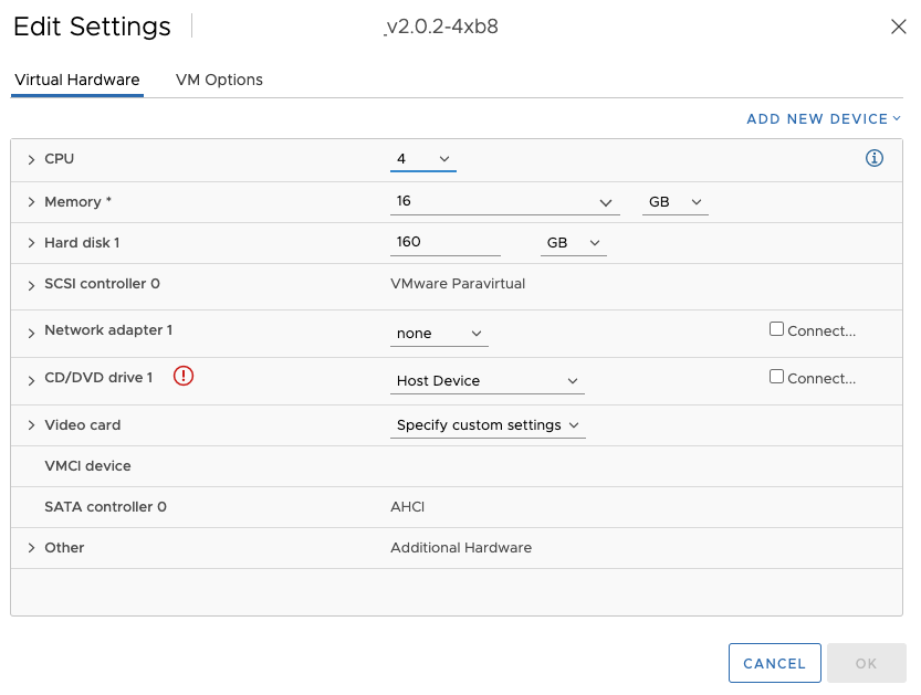
Click the Actions menu of the virtual machine, click Edit Settings and then select the Virtual Hardware tab.
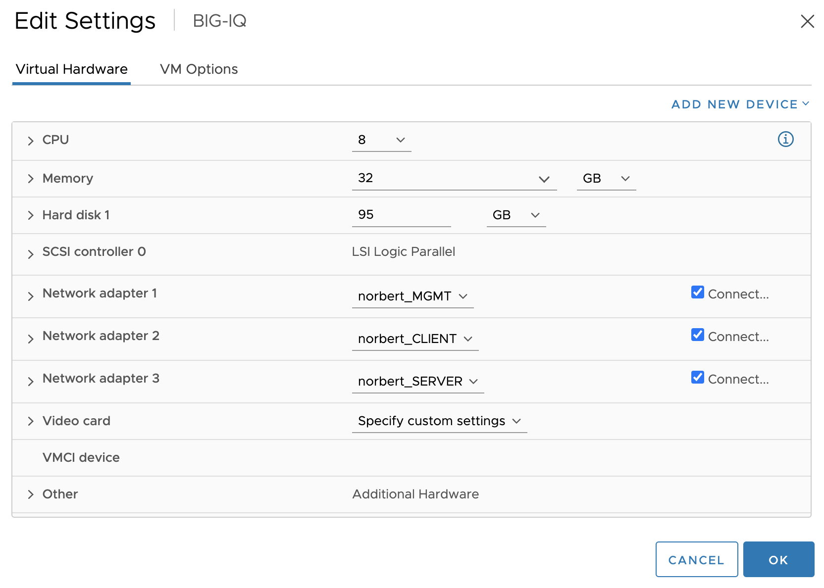
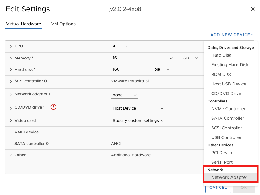
Click Add New Device and select Network Adapter from the list. The New Network section is added to the list in the Virtual Hardware tab.
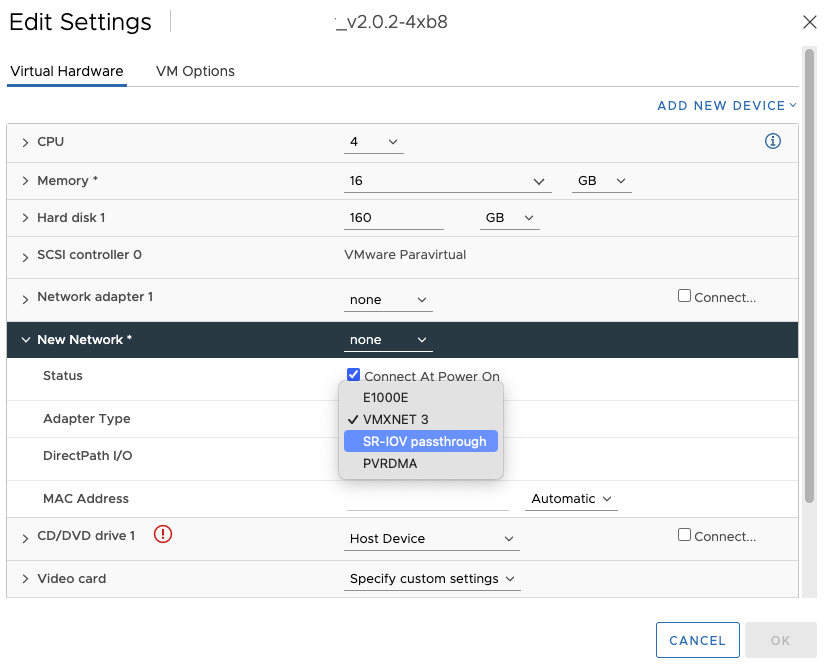
Expand the New Network drop-down menu, connect the virtual machine to a port group.
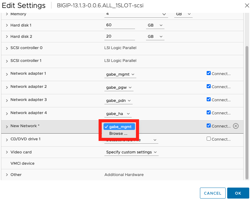
The virtual NIC does not use this port group for data traffic. The port group is used to extract the networking properties, for example VLAN tagging, to apply on the data traffic.
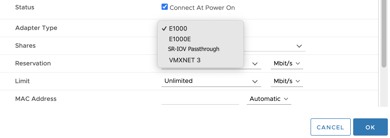
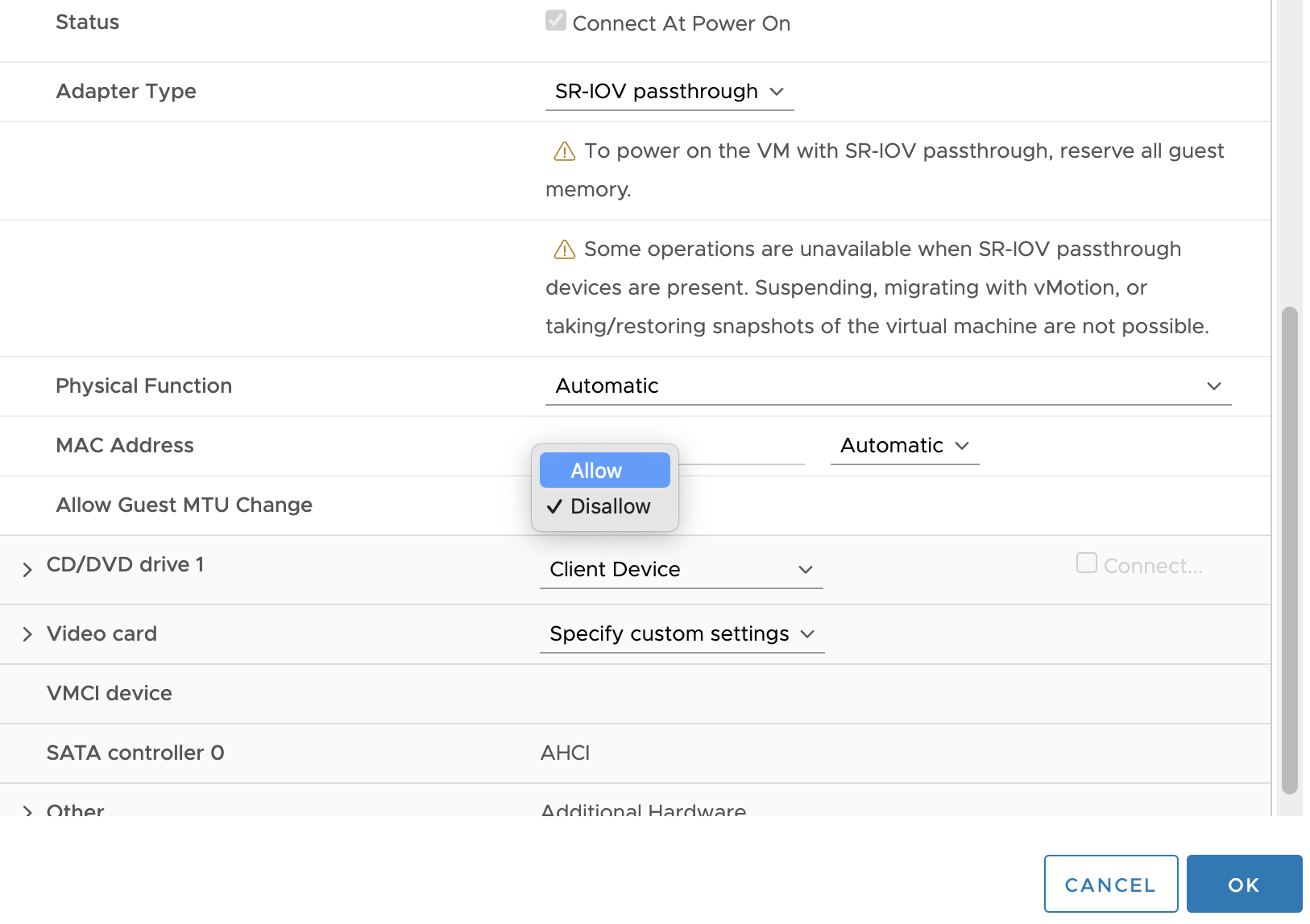
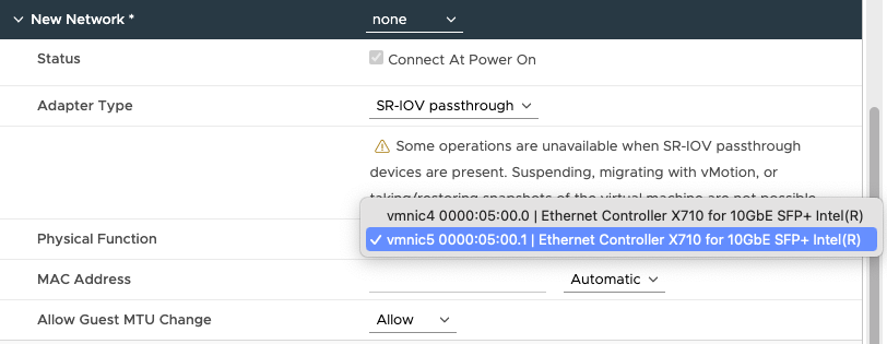
From the Adapter type drop-down menu, select SR-IOV passthrough.
From the Physical function drop-down menu, select the physical adapter to back the passthrough virtual machine adapter.
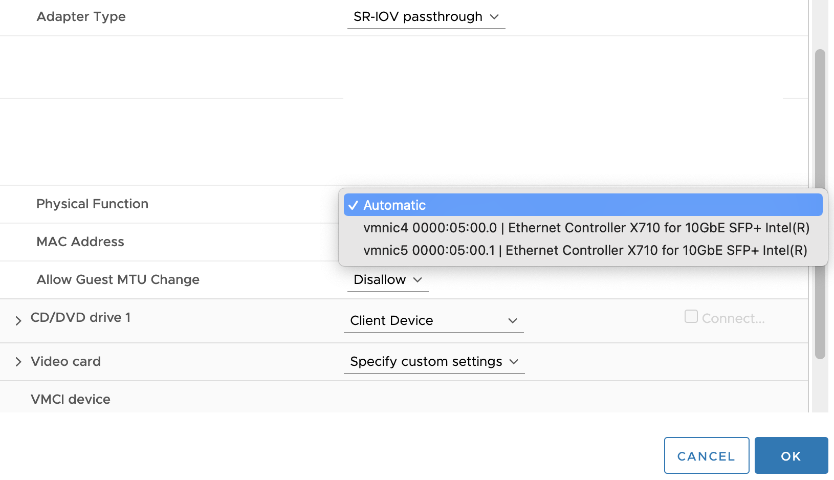
To allow changes in the MTU of packets from the guest operating system, expand the Allow Guest MTU Change drop-down menu, and then select Allow.
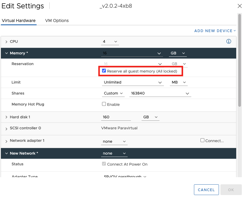
Scroll up the Edit Settings dialog box, expand the Memory section, select Reserve all guest memory (All locked) and click OK.
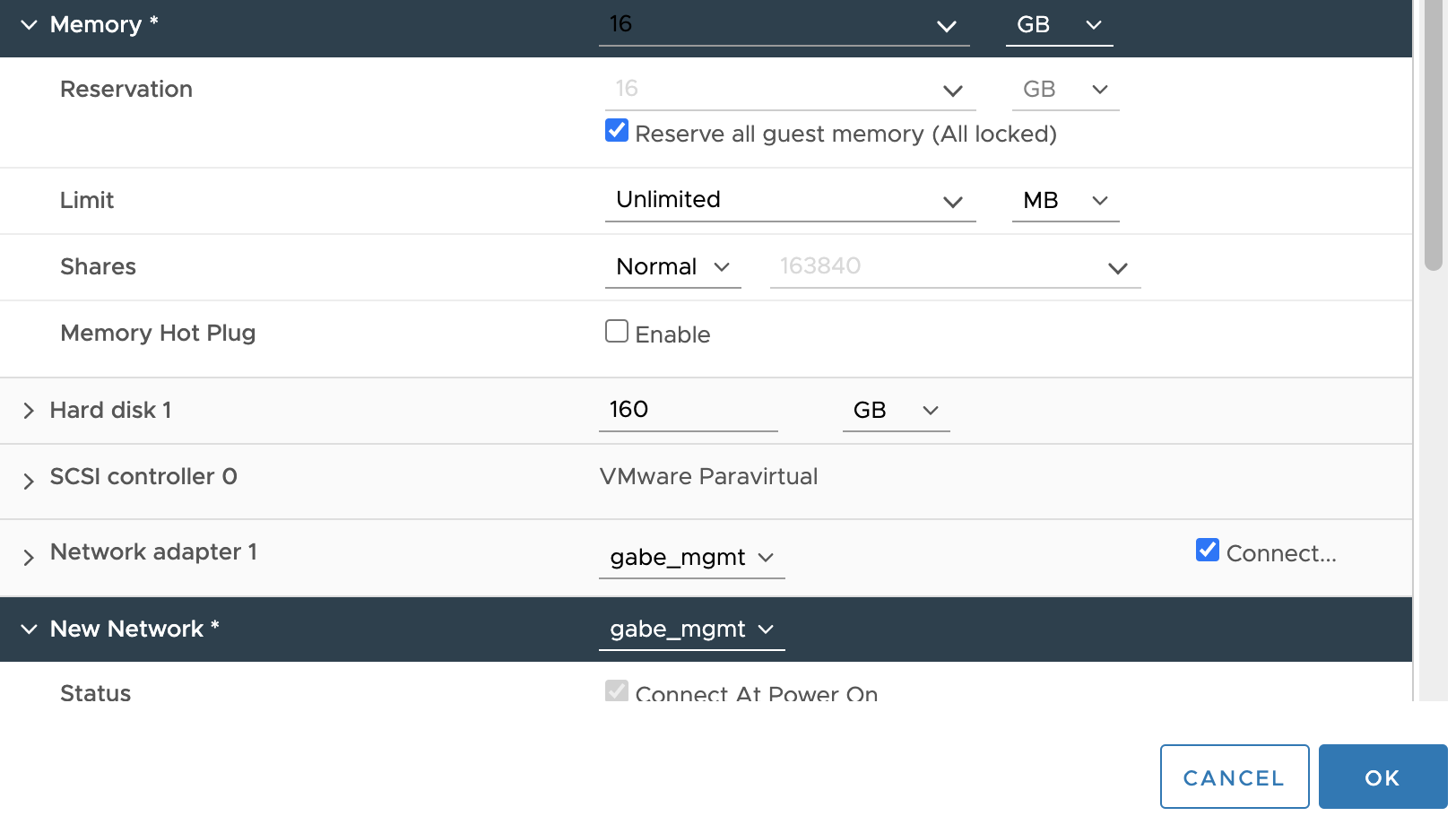
I/O memory management unit (IOMMU) must reach all virtual machine memory so that the passthrough device can access the memory by using direct memory access (DMA).
Power on the virtual machine.
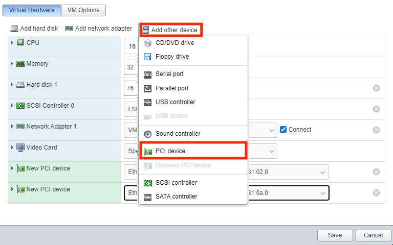
Using ESXi 6.7 and earlier with the i40e driver, enable SR-IOV on PCI device
Open the ESXi UI, verify that the SR-IOV NIC appears in the Settings area of the guest, as a PCI device. If the NIC does not appear, reboot the vSphere UI.
After rebooting (if required), in the ESXi GUI, do the following to configure SR-IOV:
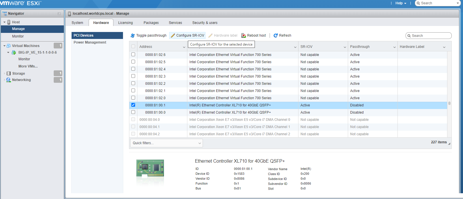
In the left menu, expand Host, select Manage, and then click the Hardware tab.
In the PCI Devices list, click to select the individual PF for the NIC, and then click Configure SR-IOV.
Select Yes, set the Virtual Function value, and then click Save.
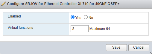
Repeat these steps for each PF on which you want to enable SR-IOV.
Edit or create a new VM, assign a PCI device corresponding to the desired VF, ensuring that the VF matches the correct PF.
OPTIONAL: To enable SR-IOV for supported Intel NICs, you must load the ixgbe driver and block the ixgbevf driver. To troubleshoot, consider the following:
To check the current ixgbe (1G-NIC) driver settings, in vSphere access the command-line tool,
esxcli, and type the following:esxcli system module parameters list -m ixgbeSet the ixgbe driver settings. In this example, 8,8 is for a 2-port card with 16 virtual functions.
esxcli system module parameters set -m ixgbe -p "max_vfs=8,8"
If you do not set the MAX VF value using the driver, then the NIC will default to 64 MAX VFs per interface.
To check the PCI bus and verify that you see the VFs (with the same number of VFs on each port), using the ESXi Console:
# lspci -D | grep IntelThe maximum number of VFs must correlate with the value set. To verify the correct settings, type:
esxcli system module parameters list -m ixgbeTo set or adjust the ixgbe driver max VF settings, type:
esxcli system module parameters set -m ixgbe -p "max_vfs=16,16"In this example, 16,16 is for a 2-port card with a total of 32 virtual functions. The maximum number of VFs per interface set must correlate to the per port VFs set in the driver.
Enable Mellanox NIC SR-IOV on ESXi
For original steps, consult Mellanox documentation for setting the VM in SR-IOV Mode.
Prerequisites:
- The VM version is Rel. 10 or above, otherwise SR-IOV will not appear as an option in the network adapter selection (if not Rel. 10 or above, then upgrade it by accessing the Compatibility section).
- Before you start, power off the VM.
- After you enable the Virtual Functions on the host, each of them becomes available as a PCI device.
Assign Virtual Function to a Virtual Machine in ESXi
Locate the Virtual Machine in the vSphere Web Client.
- Select a data center, folder, cluster, resource pool, or host, click the Summary tab, and then scroll to the Related Objects pane.
- Click Host, click the VM tab, and then select the virtual machine from the list.
Power off the Virtual Machine.
Click Actions, and then select Edit Settings.
Click Add New Device, and then select Network Adapter from the list.
Expand the New Network drop-down menu, and do the following:
Connect the virtual machine to a port group. The virtual NIC does not use this port group for data traffic. The port group is used to extract the networking properties, for example VLAN tagging, to apply on the data traffic.
Expand Adapter Type, and then select the SR-IOV passthrough connectivity option.
Expand the Physical function drop-down menu, select the physical adapter to back the passthrough virtual machine adapter.
Scroll up the Edit Settings dialog window, expand the Memory menu, and then select the Reserve all guest memory (All locked) checkbox.
I/O memory management unit (IOMMU) must reach all Virtual Machine memory so that the passthrough device can access the memory by using direct memory access (DMA).
Power on the VM.
Open the VM command line and verify that you have the interface connected. On the guest VM install the OS Mellanox driver (OFED, WinOF, etc.), and then configure the IP address and check network connectivity.
Troubleshooting tips:
Configure at least one more VF on the firmware than is configured on the driver. This example has eight VFs configured on the firmware while four are configured on the driver.
Perform
mlxconfigfor each PCI device (adapter). Also for the driver, the configuration is per module; therefore, applying to all adapters installed on the server.Verify the VM version is Rel. 10 or later, otherwise SR-IOV will not appear in the network adapter list (if not, upgrade it using the Compatibility section).
If the maximum number of VFs appears incorrect in the GUI, then check the driver using the CLI:
esxcli system module parameters list -m nmlx5_coreEnable SR-IOV in the
nmlx5_coredriver and set themax_vfsmodule parameter:esxcli system module parameters set -m nmlx5_core -p "max_vfs=8,8"In this example, 8,8 is for a 2-port card with a total of 16 virtual functions.
To check the PCI bus and verify that there are the same number of VFs on each port, use the ESXi CLI:
# lspci -D | grep Mellanox
Virtual machine memory requirements
The guest should have a minimum of 4 GB of RAM for the initial 2 virtual CPUs. For each additional CPU, you should add an additional 2 GB of RAM.
If you license additional modules, you should add memory.
| Provisioned memory | Supported modules | Details |
|---|---|---|
| 4 GB or fewer | Two modules maximum. | AAM can be provisioned as standalone only. |
| 4-8 GB | Three modules maximum. | BIG-IP DNS does not count toward the module limit. Exception: Application Acceleration Manager (AAM) cannot be provisioned with any other module; AAM is standalone only. |
| 8 GB | Three modules maximum. | BIG-IP DNS does not count toward the module-combination limit. |
| 12 GB or more | All modules. | N/A |
Important
To achieve licensing performance limits, all allocated memory must be reserved.
Virtual machine storage requirements
The amount of storage you need depends on the BIG-IP modules you want to use, and whether or not you intend to upgrade.
| Provisioned storage | Supported modules | Details |
|---|---|---|
| 9 GB (LTM_1SLOT) | Local Traffic Manager (LTM) module only; no space for LTM upgrades. | You can increase storage if you need to upgrade LTM or provision additional modules. |
| 40 GB (LTM) | LTM module only; space for installing LTM upgrades. | You can increase storage if you decide to provision additional modules. You can also install another instance of LTM on a separate partition. |
| 60 GB (ALL_1SLOT) | All modules except Secure Web Gateway (SWG); no space for installing upgrades. | The Application Acceleration Manager (AAM) module requires 20 GB of additional storage dedicated to AAM. If you are not using AAM, you can remove the datastore disk before starting the VM. |
| 82 GB (ALL) | All modules except SWG and space for installing upgrades. | The Application Acceleration Manager (AAM) module requires 20 GB of additional storage dedicated to AAM. If you are not using AAM, you can remove the datastore disk before starting the VM. |
For production environments, virtual disks should be deployed Thick (allocated up front). Thin deployments are acceptable for lab environments.
Note
To change the disk size after deploying the BIG-IP system, see Increase disk space for BIG-IP VE.
Virtual machine network interfaces
When you deploy BIG-IP VE, a specific number of virtual network interfaces (vNICs) are available.
Four vNICs are automatically defined for you.
- For management access, one VMXNET3 vNIC or Flexible vNIC.
- For dataplane access, three VMXNET3 vNICs.
Each virtual machine can have a maximum of 10 virtual NICs.
Deploy BIG-IP Virtual Edition in ESXi
To deploy BIG-IP VE, download a template from F5 and deploy it in your environment.
In a browser, open the F5 Downloads page and log in.
On the Downloads Overview page, click Find a Download.
Under Product Line, click the link similar to BIG-IP v.x/Virtual Edition.
Click the link similar to x.x.x_Virtual-Edition.
If the End User Software License is displayed, read it and then click I Accept.
Click one of the VMware files that ends with
scsi.ova.Start the vSphere client and log in.
From the vSphere File menu, choose Deploy OVF Template.
Browse to the .ova file and click Next.
The template is verified.
Click Next and complete the wizard. Note the following.
Section Details Configuration Choose from the available configurations. You can change CPU or RAM later. Storage If you decide to increase storage later, you must also adjust the BIG-IP directories to use the extra storage space. See Increase disk space for BIG-IP VE. Datastore Choose Thick for production environments. Thin is sufficient for lab environments. Source Networks The wizard leads you through creating four networks: internal, external, management, and high availability (HA). Ready to Complete If you want to deploy with the four default networks, then select the Power on after deployment check box. If you want a single NIC deployment, do not select this check box. Click Finish.
For a single NIC deployment, edit the virtual machine’s properties and remove Network adapter 2, 3, and 4. Then power on the virtual machine.
The virtual machine is created, as well as two user accounts:
- The
rootaccount provides access locally, using SSH, or the F5 Configuration utility. Therootaccount password isdefault. - The
adminaccount password isadmin. Theadminaccount provides access through the web interface.
You should change passwords for both accounts before bringing a system into production.
If you need to create a redundant configuration, place the two BIG-IP VE virtual appliances (the active-standby pair) on separate physical hosts. You can accomplish this in one of two ways:
- Manually create a virtual machine peer on each host.
- If you are using VMware Dynamic Resource Scheduler (DRS), create a DRS rule with the Separate Virtual Machine option that includes each BIG-IP VE in the pair.
Set the BIG-IP VE management IP address and passwords
When you deploy BIG-IP VE:
- If you have DHCP in your environment, a management IP address is assigned.
- If you lack DHCP, a generic management IP address (
192.168.1.245) is assigned. - A password is assigned to the default accounts:
root(default) andadmin(admin).
In ESXi 5.5 u2, 6.0, 6.5, and later, you can specify a specific management IP address (IPv4 or IPv6) and different default passwords.
There are many ways to do this.
- Before deploy, by editing the OVA file’s properties:
- Using the Common OVF Tool (COT)
- Editing the OVA descriptor file
- Using the VMware OVF tool
- Using the tool of your choice
- During deploy, by using the API of your choice to set the vApp properties
- After deploy:
- Manually updating the vApp properties
- Using a Custom Specification
- Using the BIG-IP management config tool
Important
This functionality is supported in a multi-NIC environment only.
Use Common OVF Tool to set management IP address and default passwords
You can edit the OVA (template) properties so that when you deploy BIG-IP VE, you can specify values for the management IP address and default passwords. To edit the OVA, you can use the Common OVF Tool (COT).
For more information about COT, see Common OVF Tool (COT) documentation.
Copy the OVA to a machine with enough free space (at least two times the OVA file size).
Run a command like the following:
cot edit-properties <source filename>.ova -p net.mgmt.addr=""+string -p net.mgmt.addr6=""+string -p net.mgmt.gw=""+string -p net.mgmt.gw6=""+string -p user.root.pwd=""+string -p user.admin.pwd=""+string -u -o <destination filename>.ovaNote
+stringspecifies the type of each parameter, but leaves the value for each parameter empty.
The OVA properties are updated.
Then, when you deploy the OVA file, you can specify the values.
Note
After you set the IP address and password, if you want to set it again, you must first delete this file on BIG-IP: /shared/vadc/.ve_cust_done
OVA properties file for setting management IP address and default passwords
You can edit the OVA (template) properties so that when you deploy BIG-IP VE, you can specify values for the management IP address and default passwords.
Before deploy, you can extract the contents of the OVA file to edit the OVF properties directly.
Modify the OVF file and add the following properties to the <ProductSection> area of the descriptor file.
<Category>Network properties</Category>
        <Property ovf:key="net.mgmt.addr" ovf:type="string" ovf:value="" ovf:userConfigurable="true">
        <Label>mgmt-addr</Label>
        <Description>F5 BIG-IP VE's management address in the format of "IP/prefix"</Description>
        </Property>
        <Property ovf:key="net.mgmt.addr6" ovf:type="string" ovf:value="" ovf:userConfigurable="true">
        <Label>mgmt-addr6</Label>
        <Description>F5 BIG-IP VE's management address in the format of "IPv6"</Description>
        </Property>
        <Property ovf:key="net.mgmt.gw" ovf:type="string" ovf:value="" ovf:userConfigurable="true">
        <Label>mgmt-gw</Label>
        <Description>F5 BIG-IP VE's management default gateway</Description>
        </Property>
        <Property ovf:key="net.mgmt.gw6" ovf:type="string" ovf:value="" ovf:userConfigurable="true">
        <Label>mgmt-gw6</Label>
        <Description>F5 BIG-IP VE's management default IPv6 gateway</Description>
        </Property>
<Category>User properties</Category>
        <Property ovf:key="user.root.pwd" ovf:type="string" ovf:value="" ovf:userConfigurable="true">
        <Label>root-pwd</Label>
        <Description>F5 BIG-IP VE's SHA-512 shadow or plain-text password for "root" user</Description>
        </Property>
        <Property ovf:key="user.admin.pwd" ovf:type="string" ovf:value="" ovf:userConfigurable="true">
        <Label>admin-pwd</Label>
        <Description>F5 BIG-IP VE's SHA-512 shadow or plain-text password for "admin" user</Description>
        </Property>
OVF tool for setting management IP address and default passwords
You can edit the OVA (template) properties so that when you deploy BIG-IP VE, you can specify values for the management IP address and default passwords.
Using VMware’s OVF tool, here is an example of code you would use to deploy BIG-IP VE with these settings.
ovftool
            --sourceType=OVA \
            --acceptAllEulas \
            --noSSLVerify \
            --diskMode=thin \
            --skipManifestCheck \
            --X:logToConsole \
            --X:logLevel=verbose \
            --datastore='mylab' \
            --name='vmname' \
            --vmFolder='myfolder' \
            --deploymentOption='dualcpu' \
            --net:"Internal=Internal" \
            --net:"Management=Management" \
            --net:"HA=HA" \
            --net:"External=External" \
            --X:injectOvfEnv \
            --prop:net.mgmt.addr="10.10.10.124/22" \
            --prop:net.mgmt.addr6="2001:db8:a::123" \
            --prop:net.mgmt.gw="10.10.11.254" \
            --prop:net.mgmt.gw6="2001:db8:a::124" \
            --prop:user.root.pwd="mypassword" \
            --prop:user.admin.pwd="mypassword" \
            <path_to_bigip.ova> \
            "vi://user[@userdomain]:password@domain.com/<datacenter-name>/host/<esxi-host>"
Edit vApp to set the management IP address and default passwords
After you deploy a VM running BIG-IP VE, you can manually assign a management IP address and root and admin passwords. Use this procedure if you want to set these values one time on a specific VM.
Note
These instructions may differ slightly, based on your version of vSphere.
Stop the VM.
Right-click the VM and choose Edit Settings.
Click the vApp Options tab.
In the Authoring section, expand the Properties area.
Click New.
On the Edit Property Settings window, complete the fields.
Category Label Key ID Type BIG-IP VE admin-pwd user.admin.pwd String Important: The password can be plain text or SHA-512 encrypted.
Click OK.
Create three more properties, using these values:
Category Label Key ID Type BIG-IP VE root-pwd user.root.pwd String BIG-IP VE mgmt-addr net.mgmt.addr String BIG-IP VE mgmt-addr6 net.mgmt.addr6 String BIG-IP VE mgmt-gw net.mgmt.gw String BIG-IP VE mgmt-gw6 net.mgmt.gw6 String Important: The Key ID must be the exact value shown in the table.
Scroll up and you should now have these settings available:
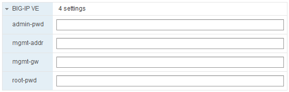
Populate these fields and click OK.
Start the VM. The properties are applied.
After you set the IP address and password, if you want to set it again, you must first delete this file: /shared/vadc/.ve_cust_done
Use Customization Specification to set management IP address
You can prompt the user to enter an IP address and mask after BIG-IP VE is deployed. To do this, you can create a VMware Custom Specification that you can reuse on multiple VMs.
Note
- These instructions may differ slightly, based on your version of vSphere.
- This procedure is for setting the management IP address; not for setting default passwords.
- You can do this procedure after you deploy, not during.
Ensure the BIG-IP VE instance is powered off.
Create a Custom Specification policy.
Open the vSphere Client Home page.
In the Navigator pane, under Policies and Profiles, click Customization Specification Manager.
Click Create a new specification.
Page Setting Value Specify Properties Target VM Operating System Linux Set Computer Name Use the virtual machine name Recommended Set Computer Name Domain Your domain Time Zone Area Your area/time zone Configure Network Manually select custom settings Create four NICs (management, internal, external, HA). For the management NIC, click Edit the selected adapter. Then for IPv4 or IPv6, click Prompt the user for an address when the specification is used and click OK.
If you enter static values, they are applied. However, if you want to re-use this Custom Spec, then prompt the user.
Note: For IPv6, you must set values for both IPv4 and IPv6.
Enter DNS and Domain Settings Not supported. You may have to enter a value to move past this page.
Edit the VM to use this policy.
- Right-click the VM and choose .
- Select your specification from the list and click OK.
Note
After you set the IP address and password, if you want to set it again, you must first delete this file: /shared/vadc/.ve_cust_done
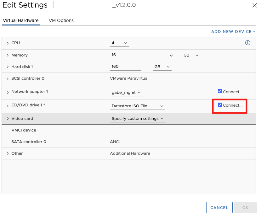
Important
After customizing your guest OS, verify that your VM interfaces are still connected. Click the Configure tab, expand the Settings blade, click Virtual Hardware menu, and then click Edit. Verify that each network adapter is still connected. If disconnected, then click to select the Connected checkbox for each disconnected interface ID.
Advanced configuration using Cloud-Init
Beginning with BIG-IP version 13.0, you can leverage Cloud-Init to pass user data (typically a startup script) to the BIG-IP. Create an ISO (Config-Drive format which was initially created for OpenStack), containing your startup script and deploy your Virtual Machine with that ISO attached as CD/DVD. For more details about the script format, see Cloud-Init and BIG-IP VE.
Upload your .ISO file into your datastore, and then launch your virtual machine.
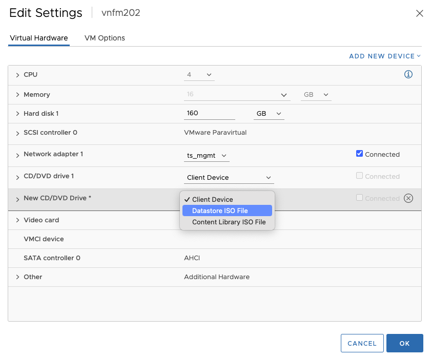
Select your VM in the list, at the top of the pane click Actions, select Edit Settings, click the Virtual Hardware tab, and then click Add New Device.
Select CD/DVD Drive from the list.
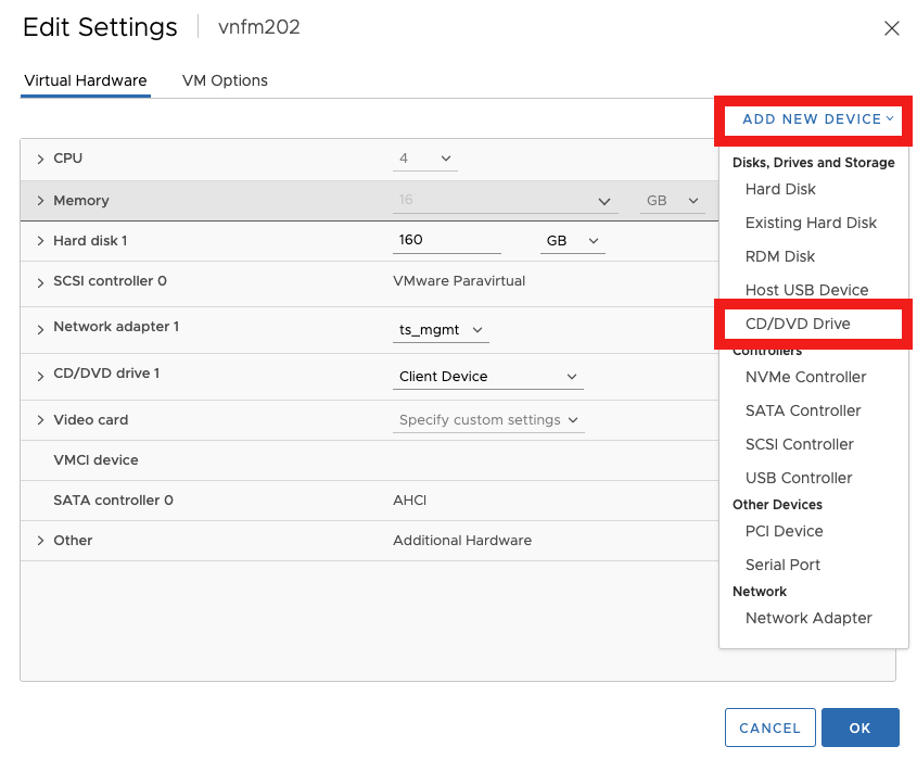
On the Edit Settings dialog window, in the New CD/DVD Drive row, expand the Client Device dropdown menu, select the Datastore ISO file option, and then browse to and select your .ISO file and click OK.
Power on your Virtual Machine.

Your startup .ISO script for the BIG-IP is attached as a CD/DVD drive.
Use BIG-IP configuration utility tool to set management IP address
If your network has DHCP, an IP address is automatically assigned to BIG-IP VE during deployment. You can use this address to access the BIG-IP VE Configuration utility or tmsh command-line utility.
If no IP address was assigned, you can assign one by using the BIG-IP Configuration utility tool.
Connect to the virtual machine by using the hypervisor’s console.
At the login prompt, type
root.At the password prompt, type
default.Note
If prompted, change your password.
Type
configand press Enter.The F5 Management Port Setup screen opens.
Click OK.
Select No and follow the instructions for manually assigning an IP address and netmask for the management port.
You can use a hypervisor generic statement, such as
tmsh show sys management-ipto confirm that the management IP address was set properly.You can now log into the BIG-IP VE Config utility using a browser, and license and provision BIG-IP VE.
Configure SR-IOV on the guest
Before you can complete these steps, you must have configured Single Root I/O Virtualization (SR-IOV) on the hypervisor.
After deploying BIG-IP VE, to configure SR-IOV on the guest, you must add three PCI device NICs and map them to your networks.
In vSphere, delete the existing Source Networks for: External, Internal, and HA.
Important: Leave the Source Network for Management.
Edit the settings for the virtual machine to add a PCI device.
If your hypervisor was set up correctly, there will be 16 virtual functions on each port (05:10.x and 05:11:x).
Map the new device to the VLAN for your internal subnet.
Repeat steps 2 and 3 for the external and HA VLANs.
When all four destination networks are correctly mapped, click Next.
The Ready to Complete screen opens.
See Also
- Update BIG-IP VE
- VMware ESXi: BIG-IP VE User’s Guide
- Best practices for deploying BIG-IP VE on VMware
- Knowledge Article K17204 about SR-IOV NIC adapters