F5 BIG-IP SSL Orchestrator Training Lab > All SSL Orchestrator Lab Guides > SSLO 202: More Use Cases with F5 BIG-IP SSL Orchestrator (AppWorld 2025 | 2 hours) > 2. Lab 1: Inbound Gateway Topology Source | Edit on
2.3. Create an Inbound Gateway Mode Topology
Now that the pre-requisite configuration has been added, you can begin creating your first SSL Orchestrator Topology.
2.3.1. Create Topology
Scroll to the bottom of the Configuration introduction page and click on the Next button to start creating a new Topology.
Enter
l3_inbound_gwas the topology name.Select the L3 Inbound topology type.
Select the Gateway mode.
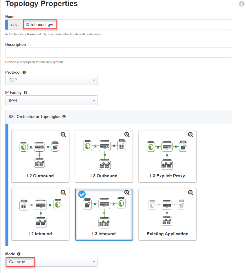
Scroll down to the bottom of the page and click on the Save & Next button to proceed to the next step in the configuration workflow.

2.3.2. Create SSL Configuration
On the SSL Configurations page, create the Client-side SSL profile for the first application (jsapp1.f5labs.com).
In the Name field, enter
jsapp1_f5labs_com(overwrite the default value).In the SNI Server Name (FQDN) field, enter
jsapp1.f5labs.com. This will be used to match the SNI provided by the client to this profile.Since you will be attaching multiple client SSL profiles, you must make one of them the default to handle the case when no SNI match is found. Enable the checkbox for Default SNI.
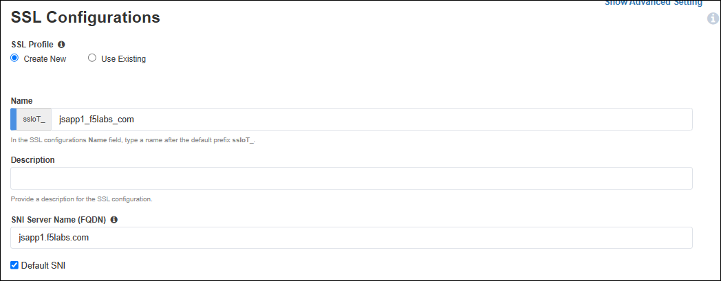
In the Certificate Key Chain section, click on the Edit (pencil) icon.
In the Certificate drop-down list, select jsapp1.f5labs.com to replace the default value.
In the Key drop-down list, select jsapp1.f5labs.com to replace the default value.
In the Chain drop-down list, select subrsa.f5labs.com.
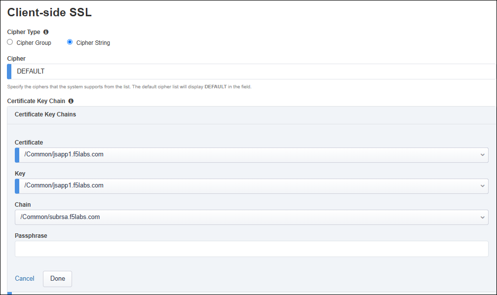
Click on the Done button to apply the config change.
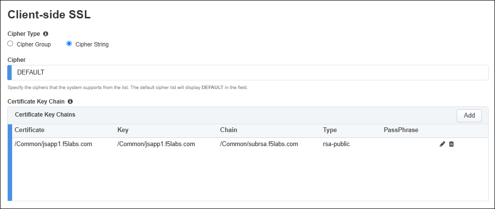
Note
You will create the Client-side SSL profile for the second application (jsapp2.f5labs.com) later.
Leave the default Server-side SSL settings.
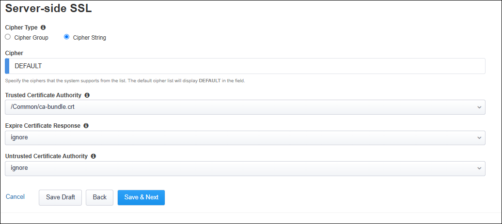
Click on the Save & Next button to continue.
2.3.3. Create Services
Now, you will create two inspection services: FireEye NX Inline Layer 2 and F5 Advanced WAF (On-box).
Click on the Add Service button to create the first service.

Double-click on the FireEye NX Inline Layer 2 service catalog icon to add it.
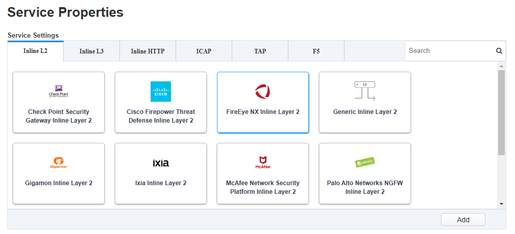
Leave the default Name of FEYE.
Click on the Add button in the Network Configuration section and use the following settings:
Under From BIGIP VLAN, click on the Create New radio button.
Enter
FEYE_inin the Name field.Select 1.4 from the Interface drop-down list.
Leave the Tag field empty.
Under To BIGIP VLAN, click on the Create New radio button.
Enter
FEYE_outin the Name field.Select 1.5 from the Interface drop-down list.
Leave the Tag field empty.
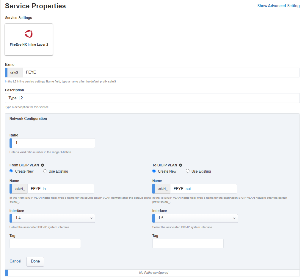
Click on the Done button to apply the settings.
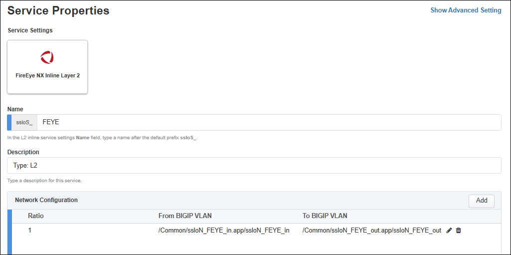
Leave the default gateway_icmp Device Monitor selection.
Select Enable Port Remap and set the port to
8080.

Click on the Save button to return to the Services list.
Click on the Add Service button to create the second service.
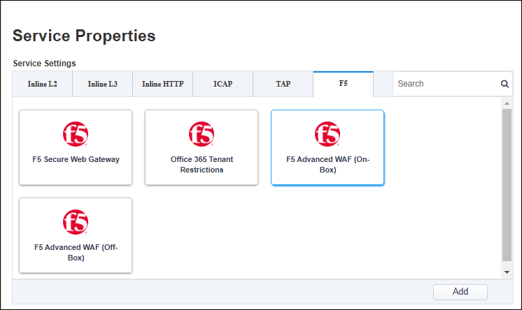
Click on the F5 tab to display F5-specific services.
Double-click on the F5 Advanced WAF (On-Box) service catalog icon to add it.
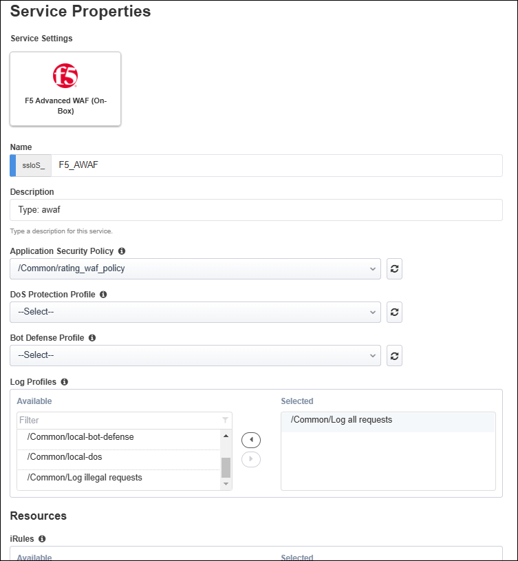
Leave the default Name of F5_AWAF.
From the Application Security Policy drop-down list, select the rating_waf_policy policy that you created earlier.
Note
You have the option to create the WAF policy within this workflow. Clicking on Create New opens a new browser tab to the WAF configuration menu. To avoid introducing any confusion in the current workflow, you created the WAF policy object prior to starting any SSL Orchestrator configuration.
Leave the default settings for the DoS Protection Profile and Bot Defense Profile options. You will not use these in this lab exercise.
In the Log Profiles section, double-click on the Log all requests profile to move it to the Selected list.
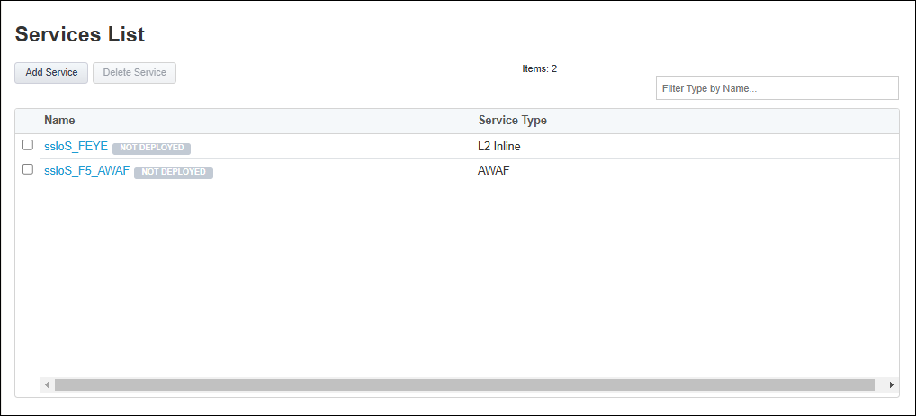
Click on the Save button to return to the Services List. You should now see both services.
Scroll down to the bottom of the page and click on the Save & Next button to proceed to the next step in the configuration workflow.
2.3.4. Create Service Chains
Create two service chains. The first one will include only the FEYE service.
From the Service Chain List, click on the Add button.

Enter
service_chain_1in the name field.Add the ssloS_FEYE service to the service chain.
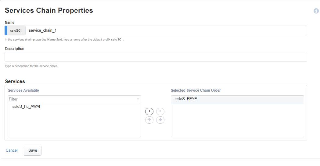
Click on the Save button.
Add a second service chain containing the FEYE and F5_AWAF service.
From the Service Chain List, click on the Add button.
Enter
service_chain_2in the name field.Add the ssloS_FEYE and the ssloS_F5 AWAF services to the service chain.
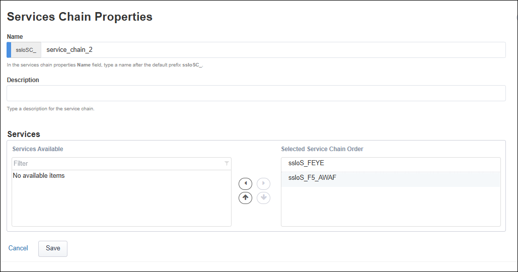
Click on the Save button.
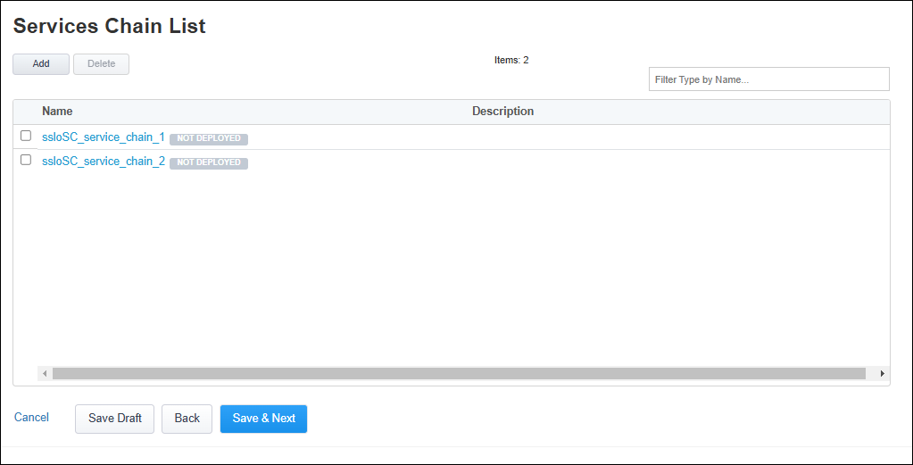
Click on the Save & Next button to continue.
2.3.5. Create Security Policy
Notice that the Security Policy contains a default All Traffic rule.

Create a new rule for the first application.
Click on the Add button on the right side of the page.
Enter
jsapp1in the rule Name field.Select the Server Name (TLS ClientHello) condition.
Enter
jsapp1.f5labs.comfor the SNI value and click on the + button to apply it.
Set SSL Proxy Action to Intercept.
Set Service Chain to ssloSC_service_chain_1.
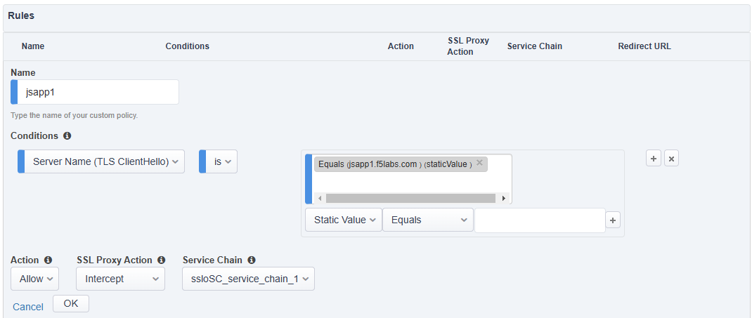
Click on the OK button to save the new rule.
Another rule will be needed for the second application.
Click on the Add button on the right side of the page.
Enter
jsapp2in the rule Name field.Select the Server Name (TLS ClientHello) condition.
Enter
jsapp2.f5labs.comfor the SNI value and click on the + button to to apply it.Set SSL Proxy Action to Intercept.
Set Service Chain to ssloSC_service_chain_2 (ensure that you select the second service chain).
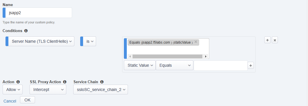
Click on the OK button to save the new rule.
Now, edit the default rule.
Click on the Edit (pencil) icon for the All Traffic rule.
Set Service Chain to ssloSC_service_chain_2.

Click on the OK button.
Your Security Policy rules should now look like the following:
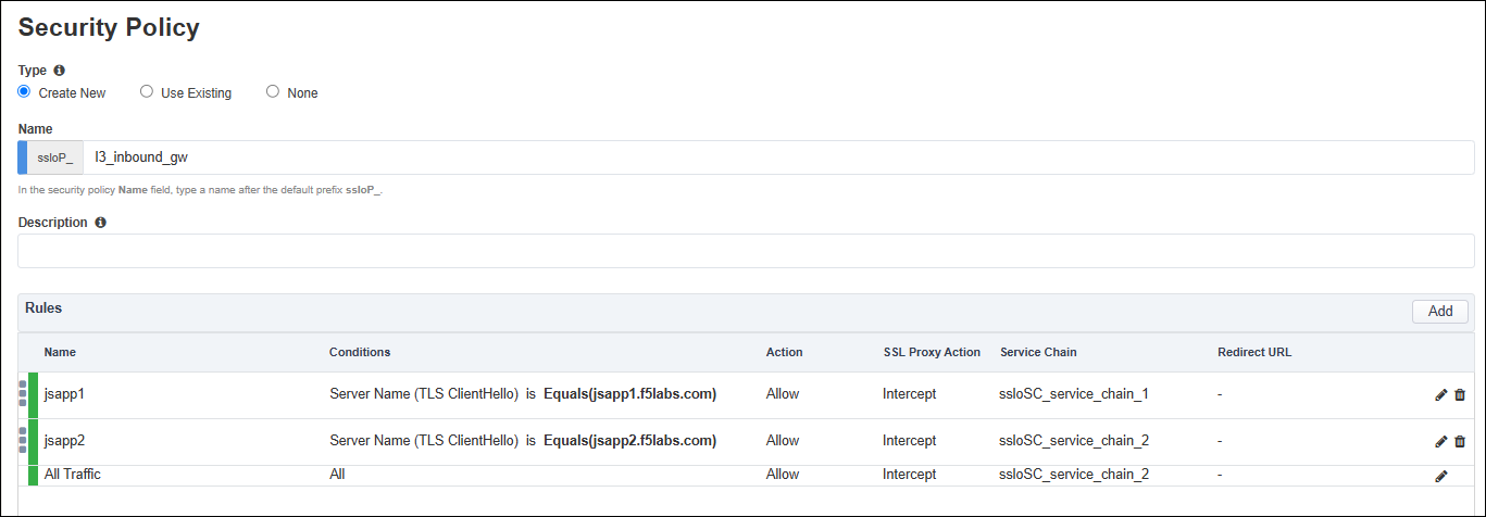
Click on the Save & Next button to continue.
2.3.6. Create Interception Rule
The Interception Rule determines what traffic to process. Since there might be a need for an L3 Outbound topology (as the outbound default route), you will define the inbound listener to match the application subnet (192.168.100.0/24).
Enter
192.168.100.0%0/24in the Destination Address/mask field.Leave the default value (0) in the Port field.
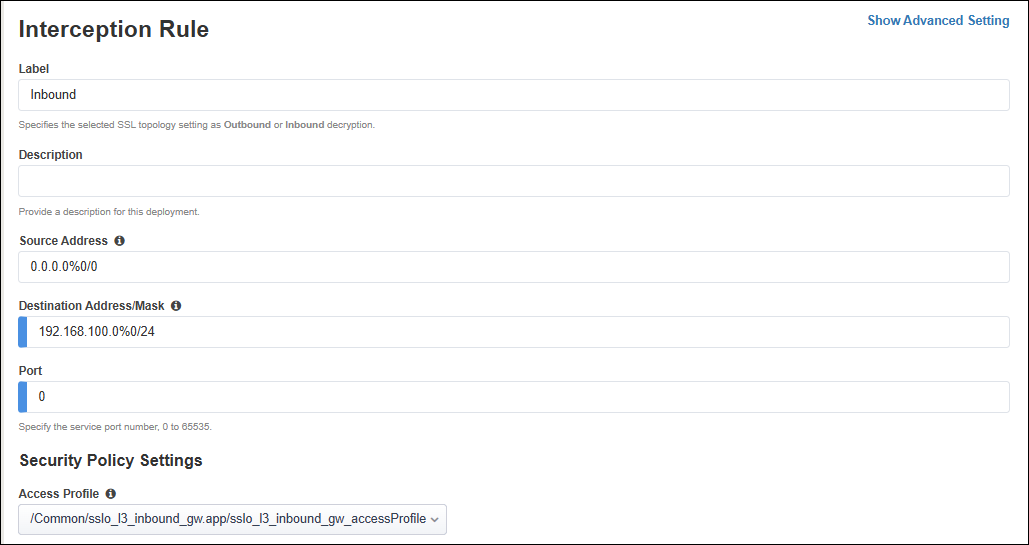
In the Ingress Network section, select the client-vlan VLAN.

In the Protocol Settings section, you should see that the jsapp1_f5labs_com SSL configuration is already selected.
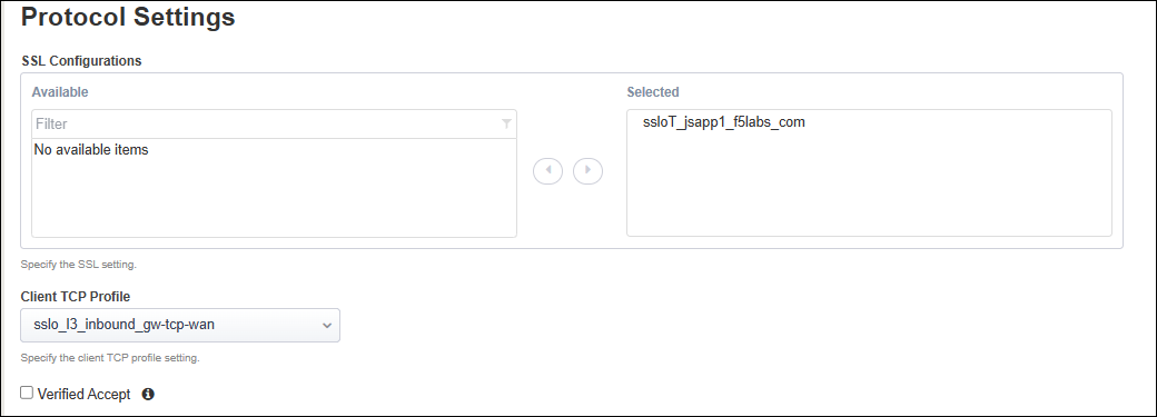
Note
You will add the second SSL Profile in a later step.
For the L7 Profile, select /Common/http.

Click on the Save & Next button to continue.
2.3.7. Create Egress Settings
You will use SNAT all egress traffic and use the default route as a gateway.
In the Manage SNAT Settings drop-down list, select Auto Map.
Leave the default Gateways setting.

Click on the Save & Next button to continue.
2.3.8. Create Log Settings
Leave the default log settings.
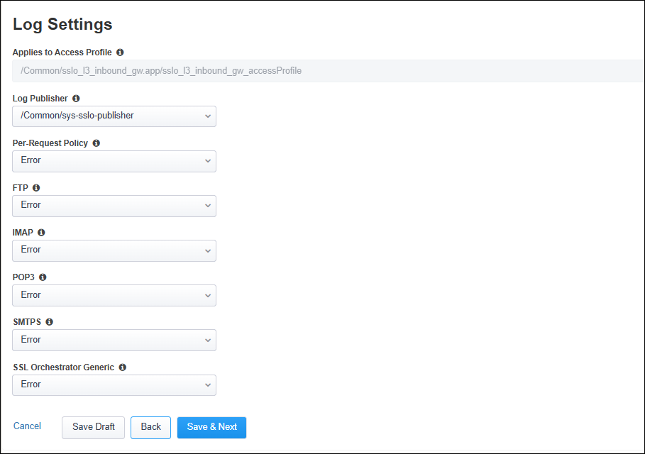
Click on the Save & Next button to continue.
2.3.9. Deploy Topology
Click on the Deploy button to create the new topology configuration.
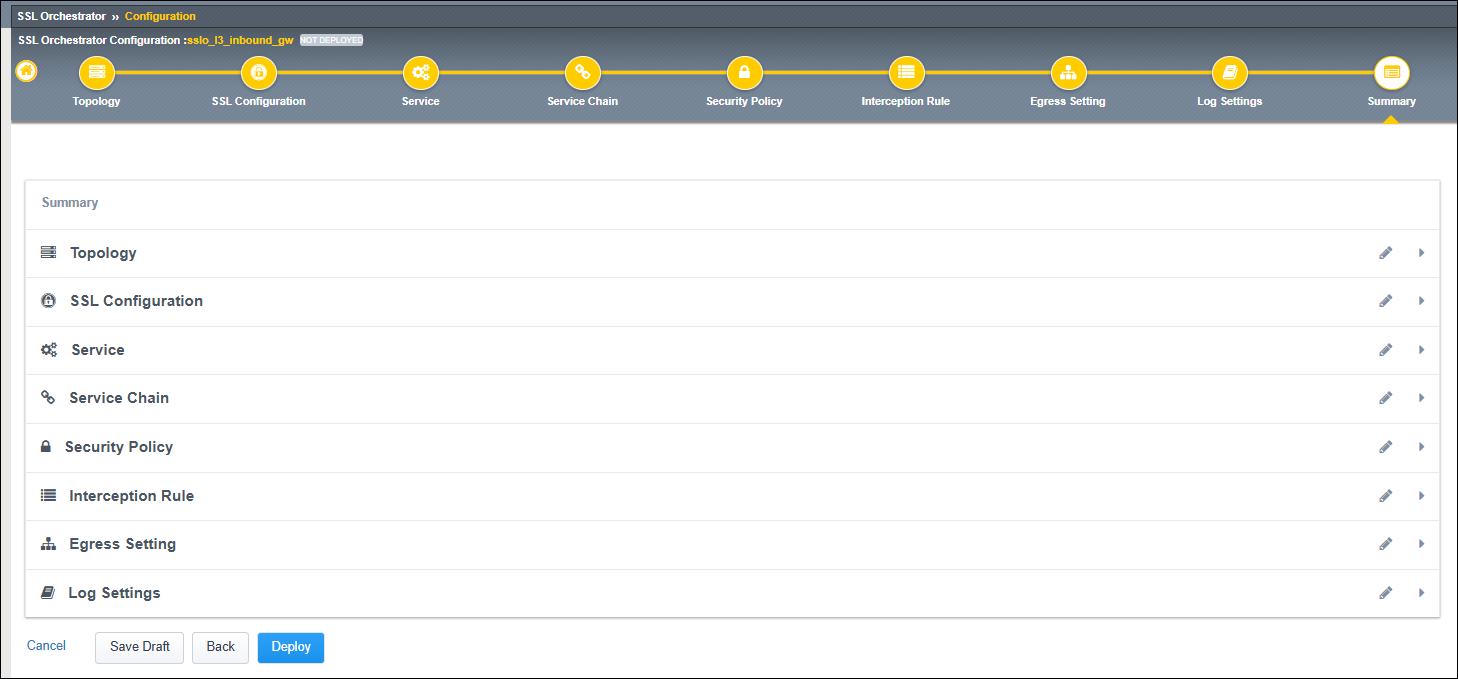
When the deployment has completed, click on the OK button to continue. You should see the new Topology in the Topologies tab.
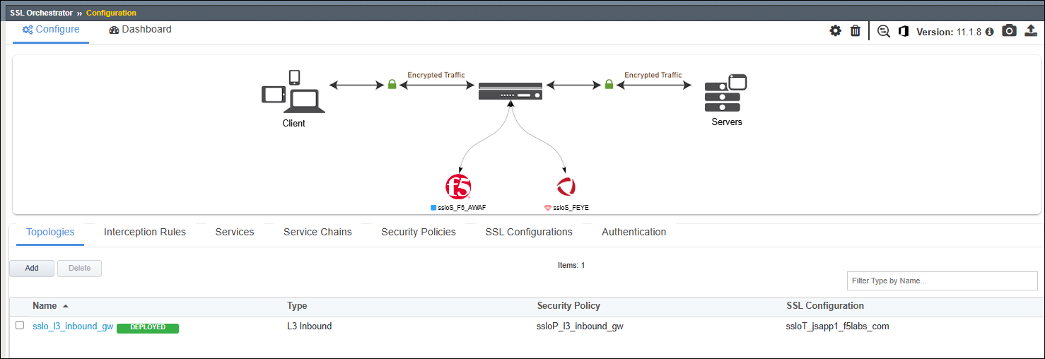
2.3.10. Create SSL Configuration for Second Application
The guided workflow only allows you to create one SSL Configuration, so you will now need to create one for the second application (jsapp2.f5labs.com) and add it to the Interception Rules.
Click on the SSL Configurations tab.
Click on the Add button.
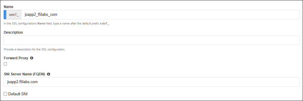
In the Name field, enter
jsapp2_f5labs_com.Disable (uncheck) the setting for SSL Forward Proxy (it is enabled by default).
Warning
If the SSL Forward Proxy option is enabled when you deploy this SSL profile, you will have to delete and re-build it. You cannot change this setting after it has been deployed.
In the SNI Server Name (FQDN) field, enter
jsapp2.f5labs.com. This will be used to match the SSL profile to the SNI value sent by the client.Since you enabled the Default SNI setting in the SSL Configuration for the first application (jsapp1.f5labs.com), DO NOT ENABLE it here.
In the Certificate Key Chain section, click on the Edit (pencil) icon.
In the Certificate drop-down list, select jsapp2.f5labs.com to replace the default value.
In the Key drop-down list, select jsapp2.f5labs.com to replace the default value.
In the Chain drop-down list, select subrsa.f5labs.com.
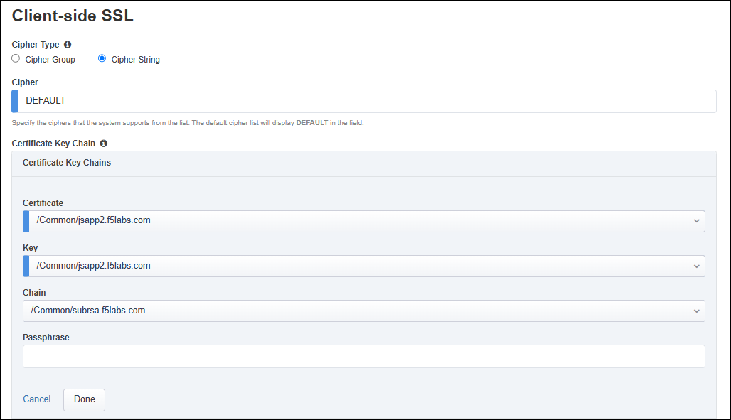
Click on the Done button to apply the config change.
Leave the default Server-side SSL settings.
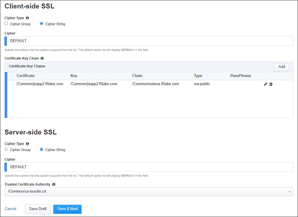
Click on the Save & Next button to continue.
Click on the Deploy button to finish creating the new SSL profile.

When the deployment has completed, click on the OK button to close the dialog box and return to the Topologies list.
Click on the SSL Configurations tab to return to the SSL profiles list.

2.3.11. Update the Interception Rule
Now, you need to add the second SSL Configuration to the Interception Rule.
Click on the Interception Rules tab.

Click on sslo_l3_inbound_gw and then click on the Edit (pencil) icon to edit the settings.

Scroll down to the Protocol Settings section and add the jsapp2 Client SSL and corresponding jsapp2 Server SSL profiles to the Selected list.
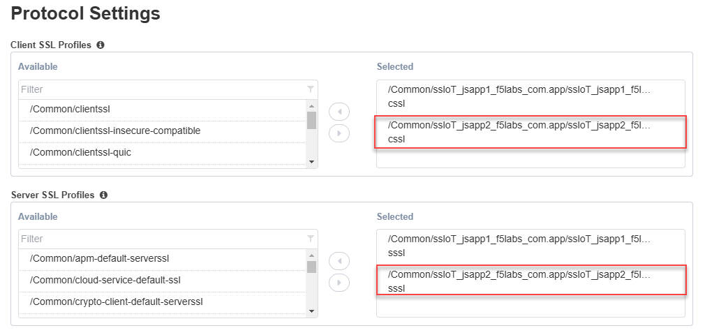
Click on the Save & Next button to return to the Interception Rules Summary.
Click on the Deploy button.
When the deployment has completed, click on the OK button to close the dialog box and return to the Topologies list.
This completes the Topology configuration.