Amazon Web Services: High Availability F5 BIG-IP Virtual Edition
If a F5® BIG-IP® Virtual Edition (VE) becomes unavailable for any reason, it can fail over to another BIG-IP VE. In the AWS environment, if the active BIG-IP VE suddenly goes offline, BIG-IP VE drops the active connections. The other BIG-IP VE processes new connections when it becomes active.
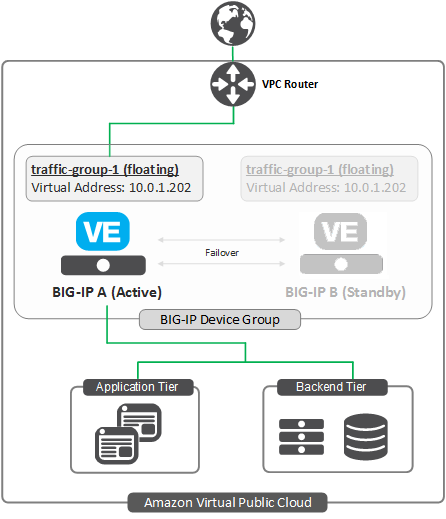
The following illustration shows an example of two BIG-IP VE instances in an Amazon VPC. The two BIG-IP VEs are members of a BIG-IP device group, which means that the BIG-IPs trust each other, they synchronize their configurations, and they can fail over to one another.
Each BIG-IP VE has the default floating traffic group, traffic-group-1, that contains a floating virtual IP address.
Application traffic is going to the virtual IP address on BIG-IP A. If BIG-IP A goes offline, the virtual IP
address becomes active on BIG-IP B and the traffic redirects to it.
Complete the tasks in this guide to create this deployment.
Alternately, you can use F5 BIG-IP Cloud Formation Templates (CFT) to create this deployment. For more information about F5 CFTs, visit https://github.com/F5Networks.
High availability configuration overview
This illustration shows the additional network objects you must create for a typical BIG-IP VE high availability (HA) configuration in AWS.
In this configuration, the BIG-IP VEs continually communicate their availability status to one another through the HA VLAN and the associated static self IP address on each BIG-IP VE.
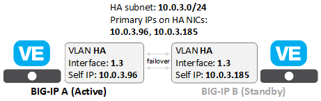
To create this configuration, in AWS, you create an HA subnet with primary private IP addresses and network interfaces. Then in BIG-IP VE, you create corresponding objects, represented by the shaded boxes in the diagram.
Task List: Create two BIG-IP VE instances
Follow the steps in the Amazon Web Services: Multi-NIC Configuration guide to create and deploy two BIG-IP VE instances (BIG-IP A and BIG-IP B) in an Amazon VPC with multiple subnets using these HA networking objects.
Note: Both BIG-IP VE instances must be in the same availability zone. For HA across availability zones, see the CFTs on https://github.com/F5Networks.
Task List: Create HA interfaces for both BIG-IP instances (A and B)
Once deployed, these instances will require you to add the following AWS resources for HA:
| Step | Task | Description |
|---|---|---|
| 1 | OPTIONAL version-dependent: Create an IAM role/policy to enable communication between BIG-IP VE and AWS and apply the role to both instances (A and B). |
|
| 2 | Create an Elastic IP address (EIP) for each BIG-IP Self-IP on the external interface. | Once a default route is configured on the external subnet, BIG-IP will use these EIPs (publically routable addresses) to communicate with the AWS API. |
| 3 | Create a subnet for HA communication. | The BIG-IPs will use a separate subnet for HA communication.
|
| 4 | Create a network interface (NIC) on the HA subnet for each BIG-IP. | These two NICs are used for HA communication.
|
| 5 | Reboot both BIG-IP instances, so they can discover the additional HA NIC. | You can use the BIG-IP CLI or the AWS UI. |
Task List: Configure high availability on BIG-IP VE
To set up high availability (HA), create these resources. This is a specific example, which you can use to test an HA configuration.
| Step | Task | Description |
|---|---|---|
| 1 | Create VLANs for HA communication. | On each BIG-IP VE, create a VLAN that corresponds to the HA subnet.
|
| 2 | Create static self IP addresses for the HA VLANs. | On each BIG-IP VE, create a static self IP address used for failover communication. These IP addresses must match the private IP addresses assigned to the HA subnet in AWS.
|
| 3 | Establish device trust. | The BIG-IP VEs must establish trust by exchanging certificates. Use management IP addresses to do this.
|
| 4 | Specify config sync and failover addresses. | These are the static self IP addresses that you want the BIG-IP VEs to use for config sync and failover operations to one another. Config sync static self IP for internal VLAN:
Static self IP for the HA VLAN:
|
| 5 | Create a Sync-Failover device group. | BIG-IP VEs in a Sync-Failover device group can sync their configurations and fail over to one another.
|
| 6 | Synchronize the BIG-IP configuration. | Log into BIG-IP A and sync its configuration to BIG-IP B. |
| 7 | Configure the F5 Cloud Failover Extension (CFE). | For BIG-IP VE 14.1.0 and LATER, use the F5 BIG-IP Cloud Failover Extension (CFE) and download the RPM from F5 GitHub repository for the following AWS HA scenarios: |
| 8 | Trigger failover to the standby BIG-IP VE | To test HA configuration, force the active BIG-IP VE to fail over to the standby peer, and then view the HA status of each BIG-IP VE. |
Create a subnet for HA communication
Each BIG-IP VE instance uses three VPC subnets, for management, external, and internal traffic. Note the availability zone for these subnets (for example, us-west-2a).
Now, in the same availability zone, create a subnet for high availability (HA) communication between the two instances. This subnet corresponds to the BIG-IP VLAN named HA that you will create later on each BIG-IP VE.
- In the AWS Management Console, from the Services menu at the top of the screen, select VPC.
- In the Navigation pane, under Virtual Private Cloud, select Subnets.
- Click Create Subnet.
- In the Name tag field, type
HA. - In the VPC field, select the VPC.
- In the Availability Zone field, select the zone where the other subnets reside.
- In the CIDR block field, type
10.0.3.0/24. - Click Yes, Create.
Your VPC should now have four subnets:
- management:
10.0.0.0 - external:
10.0.1.0 - internal:
10.0.2.0 - HA:
10.0.3.0
Create HA network interfaces
Each of your BIG-IP VE instances should have three network interfaces, one per subnet (management, external, and internal). Now create another network interface for each instance and associate it with the HA subnet.
In the AWS Management Console, from the Services menu at the top of the screen, select EC2.
In the Navigation pane, under NETWORK & SECURITY, select Network Interfaces.
Click Create Network Interface and populate the appropriate fields.
Field Value Description HA-ASubnet 10.0.3.0/24Private IP 10.0.3.96Security groups InternalTrafficNote: You do not need to create a separate security group for the HA network interfaces.
Click Yes, Create.
AWS adds the network interface to the list.
Update the name in the list to
HA-A.Right-click the new network interface and select Attach.
From the Instance ID list, select the instance for BIG-IP A and click Attach.
Repeat this task for BIG-IP B, using these values and attaching the NIC to the BIG-IP B instance:
Field Value Description HA-BSubnet 10.0.3.0/24Private IP 10.0.3.185Security groups InternalTrafficReboot both BIG-IP VEs so that they can register the new NICs. To do this, right-click each instance in the Instances list and choose .
Create VLANs for HA communication
You must create a VLAN on each BIG-IP VE. The two BIG-IP VEs will use this VLAN for high availability communication with each other.
Log in to the BIG-IP Configuration utility on BIG-IP A.
On the Main tab, click . The VLAN List screen opens.
Click Create and fill in the appropriate fields for the HA VLAN.
Field Value Name HAInterface 1.3Tagging UntaggedClick Finished.
Now log in to the BIG-IP Configuration utility on BIG-IP B.
Repeat this task, using the same name for the VLAN:
Field Value Name HAInterface 1.3Tagging UntaggedClick Finished.
After you complete this task, each BIG-IP VE has a VLAN for high availability communications that corresponds to the HA subnet in your Amazon Virtual Private Cloud (VPC).
Create static self IP addresses for the HA VLANs
Each BIG-IP VE needs a static self IP address to send failover communications to the other BIG-IP VE. This self IP address must match the primary private IP address of the instance’s network interface for the HA subnet.
Log in to the BIG-IP Configuration utility on BIG-IP A.
On the Main tab, click .
Click Create and populate the appropriate fields.
Field Value Name HASelfIP_AIP Address 10.0.3.96Netmask 255.255.255.0VLAN/Tunnel HAPort Lockdown Allow All Traffic Group traffic-group-local-only Click Finished.
Now log in to the BIG-IP Configuration utility on BIG-IP B.
Repeat this task, specifying these values:
Field Value Name HAselfIPBIP Address 10.0.3.185Netmask 255.255.255.0VLAN/Tunnel HAPort Lockdown Allow All Traffic Group traffic-group-local-only
- Click Finished.
The two BIG-IP VEs can now monitor each other’s availability status through the HA VLAN.
Establish trust between the BIG-IP VEs
Before joining a Sync-Failover device group, both BIG-IP VEs must authenticate each others’ certificates to create trust.
Note: Do this task on BIG-IP A only.
Log in to the BIG-IP Configuration utility on BIG-IP A.
On the Main tab, click , and then select Peer List.
Click Add.
For the IP address, type the management address for BIG-IP B,
10.0.0.201.This is the primary private IP address associated with BIG-IP B’s management subnet.
Type the administrative user name (admin).
Click Retrieve Device Information.
BIG-IP A discovers BIG-IP B and displays information about it.
Confirm that BIG-IP B’s certificate is correct.
Confirm that the management IP address and name of BIG-IP B are correct.
Click Finished.
BIG-IP A and BIG-IP B now trust each other.
Specify config sync, failover, and mirroring addresses
Each BIG-IP VE needs to synchronize its configuration with and assess the health of the other BIG-IP VE.
- Log in to the BIG-IP Configuration utility on BIG-IP A.
- On the Main tab, click .
- In the Name column, click BIG-IP A.
- From the Device Connectivity menu, choose ConfigSync.
- For the Local Address setting, select the static self IP address for BIG-IP A’s internal VLAN,
10.0.2.200, and click Update. - From the Device Connectivity menu, choose Failover Network.
- For the Failover Unicast Configuration settings, click Add and specify the static self IP address for BIG-IP A’s HA VLAN,
10.0.3.96. - Click Finished.
Now log in to BIG-IP B.
- On the Main tab, click .
- In the Name column, click BIG-IP B.
- From the Device Connectivity menu, choose ConfigSync.
- For the Local Address setting, select the static self IP address for BIG-IP B’s internal VLAN,
10.0.2.201, and click Update. - From the Device Connectivity menu, choose Failover Network.
- For the Failover Unicast Configuration settings, click Add and specify the static self IP address for BIG-IP B’s HA VLAN,
10.0.3.185. - Click Finished.
Now each BIG-IP VE can use the IP addresses of the other BIG-IP VE to sync its configuration and fail over.
Create a Sync-Failover device group
You must put the two BIG-IP-IP VEs into a Sync-Failover device group. If an active BIG-IP VE in the Sync-Failover device group becomes unavailable, its configuration objects fail over to the other BIG-IP VE and traffic processing resumes.
Note: Do this task on BIG-IP A only.
- Log in to the BIG-IP Configuration utility on BIG-IP A.
- On the Main tab, click .
- On the Device Groups list screen, click Create.
- Type a name for the device group, like
bigip_ve_dg. - Select the device group type Sync-Failover.
- In the Configuration area of the screen, select both BIG-IP VEs from the Available list and click the Move button.
- The BIG-IP VEs are now in the Includes list.
- Select the Network Failover check box.
- Click Finished.
You now have a Sync-Failover device group that contains both BIG-IP VEs.
Sync the BIG-IP configuration to the device group
You must synchronize the BIG-IP configuration data from BIG-IP A to BIG-IP B. This data includes the floating virtual IP address, 10.0.1.202.
Note: Do this task on BIG-IP A only.
Log in to the BIG-IP Configuration utility on BIG-IP A.
On the Main tab, click .
In the Device Groups area of the screen, from the Name column, select the device group you created earlier, such as
bigip_ve_dg.The screen expands to show a summary and details of the sync status of the device group, as well as a list of the two BIG-IP VEs within the device group.
In the Devices area of the screen, from the Sync Status column, select the device that shows a sync status of Changes Pending.
In the Sync Options area of the screen, select Sync Device to Group.
This syncs the most recent changes on BIG-IP A to the other member of bigip_ve_dg, BIG-IP B.
Configure the Cloud Failover Extension (CFE)
The F5 BIG-IP Cloud Failover Extension (CFE) is an iControl LX extension that provides L3 failover functionality in cloud environments, effectively replacing Gratuitous ARP (GARP). Using F5 CFE involves, downloading the RPM from F5 GitHub repository, uploading the RPM to BIG-IP, tagging/labeling your cloud resources, and then posting your declaration. Consult the F5 BIG-IP Cloud Failover Extension (CFE) user guide for complete steps.
Configure F5 CFE for the following AWS scenarios:
Important
F5 has validated the deployment of VE on AWS Outposts Racks that support instance types as validated in the AWS instances table. As part of this validation, F5 has confirmed that F5 BIG-IP Cloud Failover Extension (CFE) works as expected for the assignment of secondary IP addresses, routes in Outposts deployed subnets, local routes, and customer-owned Ips. F5 CFE on Outposts has the same IAM and S3 requirements as CFE running in the region, including access to region-based S3 resources. If you require no data be stored outside of AWS Outposts, then non-HA deployments are supported.
Trigger failover to the standby BIG-IP VE
Before doing this task, confirm in AWS that both BIG-IP VE instances are running.
You can test your HA configuration by forcing the active BIG-IP VE to fail over to the standby peer and then viewing the HA status of each BIG-IP VE.
Log in to the Configuration utility for both BIG-IP VEs.
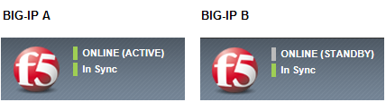
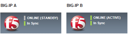
In the upper left corner, BIG-IP A should show a status of ACTIVE, while BIG-IP B shows a status of STANDBY:
In the AWS Management Console, from the Services menu at the top of the screen, select EC2.
In the Navigation pane, under NETWORK & SECURITY, select Network Interfaces.
This displays the list of EC2 network interfaces.
Find the secondary private IP address, which you will use for the virtual IP address (
10.0.1.202); this is the private IP address associated with BIG-IP A’s external interface: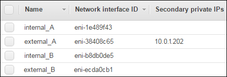
On the active BIG-IP VE (BIG-IP A), from the Main tab, click .
To the left of
traffic-group-1, select the check box.Click Force to Standby.
A confirmation message appears.
Click Force to Standby again.
In the upper left corner of the BIG-IP Configuration utility, BIG-IP A now shows a status of STANDBY, while BIG-IP B shows a status of ACTIVE:
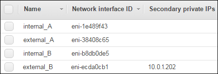
Now view the AWS list of network interfaces and find the secondary private IP address again. You can see that the IP address floated to BIG-IP B’s external interface during failover:
Troubleshooting the HA configuration
There are a few things you can do if failover is not working:
- Confirm that the Port Lockdown setting on each self IP address is Allow All.
- For the external, internal, and HA VLANs, confirm that the interface assigned to each VLAN matches the device index assigned to the corresponding subnet. For example, the internal subnet in AWS should have a device index of
eth2, and the internal VLAN in the BIG-IP software should have interface1.2assigned to it. - Check the log messages by using SSH to log in to the BIG-IP VEs. At the system prompt, type the command
tail -n 20 /var/log/ltm. This shows the most recent twenty rows of log messages. - Confirm that the two instances show the same date and time.
If none of the above solves the problem, use the BIG-IP Configuration utility to do the following:
- Delete the peer authority in the local trust domain.
- Remove the BIG-IP VEs from the device group and then delete the empty device group.
- On BIG-IP A, re-establish trust with BIG-IP B, specifying BIG-IP B’s management address,
10.0.0.201. - Re-create the Sync-Failover device group with the Network Failover setting enabled.
- On BIG-IP A, sync the configuration to the device group (in this case, BIG-IP B).
High availability networking objects
If you are having issues with your HA configuration, ensure you have all of these object properly configured.
In AWS, a VPC with:
- Network address translation (NAT)
- A subnet for the management, external, internal, and HA networks
- A security group for each subnet
- A route table entry to provide Internet access for the management and external subnets
A running instance of BIG-IP VE (called BIG-IP A) with the following:
| Location | Object | Details |
|---|---|---|
| AWS | NICs |
|
| AWS | Elastic IP | For the management interface, an Elastic IP (EIP) address, for example 52.x.x.x |
| AWS | Secondary Private IP address | For the virtual server, a secondary private IP address attached to NIC external_A: 10.0.1.202 |
| BIG-IP VE | VLANs |
|
| BIG-IP VE | Self IP addresses |
|
| BIG-IP VE | Virtual server | 10.0.1.202 |
| BIG-IP VE | Load balancing pool | HA_pool |
A running instance of BIG-IP VE (called BIG-IP B) with the following:
| Location | Object | Details |
|---|---|---|
| AWS | NICs |
|
| AWS | Elastic IP | For the management interface, an Elastic IP (EIP) address, for example 52.x.x.x |
| BIG-IP VE | VLANs |
|
| BIG-IP VE | Self IP addresses |
|
Troubleshooting failover
- If experiencing failover issues, consult the F5 BIG-IP Cloud Failover Extension troubleshooting tips.