F5 BIG-IP SSL Orchestrator Training Lab > All SSL Orchestrator Lab Guides > SSLO 203: F5 BIG-IP SSL Orchestrator: Plug, play, automate (AppWorld 2026 | 2 hours) > 2. Lab 1: Outbound Transparent Forward Proxy with User Coaching Source | Edit on
2.3. Deploy a Basic L3 Outbound Proxy Topology
In this section, you will create a basic SSL Orchestrator Topology to verify that outbound client traffic is being intercepted before enabling the user coaching function.
2.3.1. Create Topology
In the SSL Orchestrator UI, click on the Topologies tab.
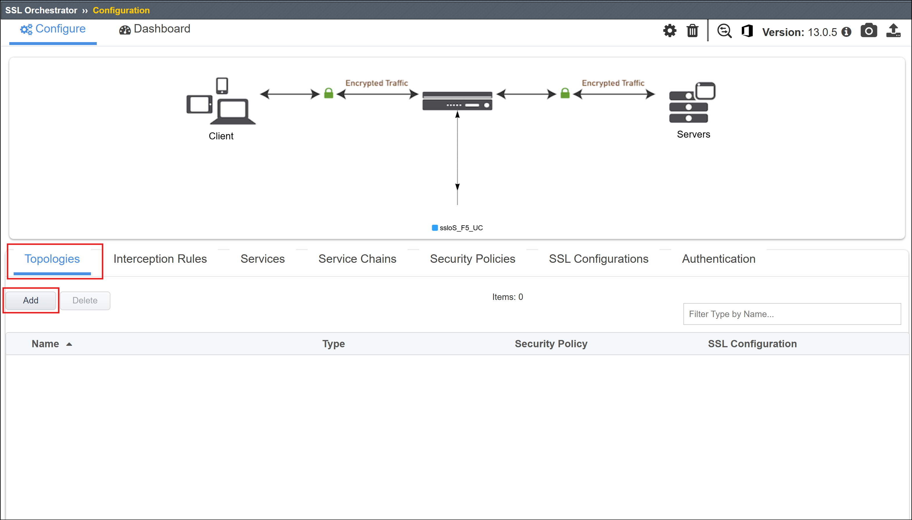
Click on the Add button to start creating a new Topology.
Scroll to the bottom of the Configuration introduction page and click on the Next button to start creating a new Topology.
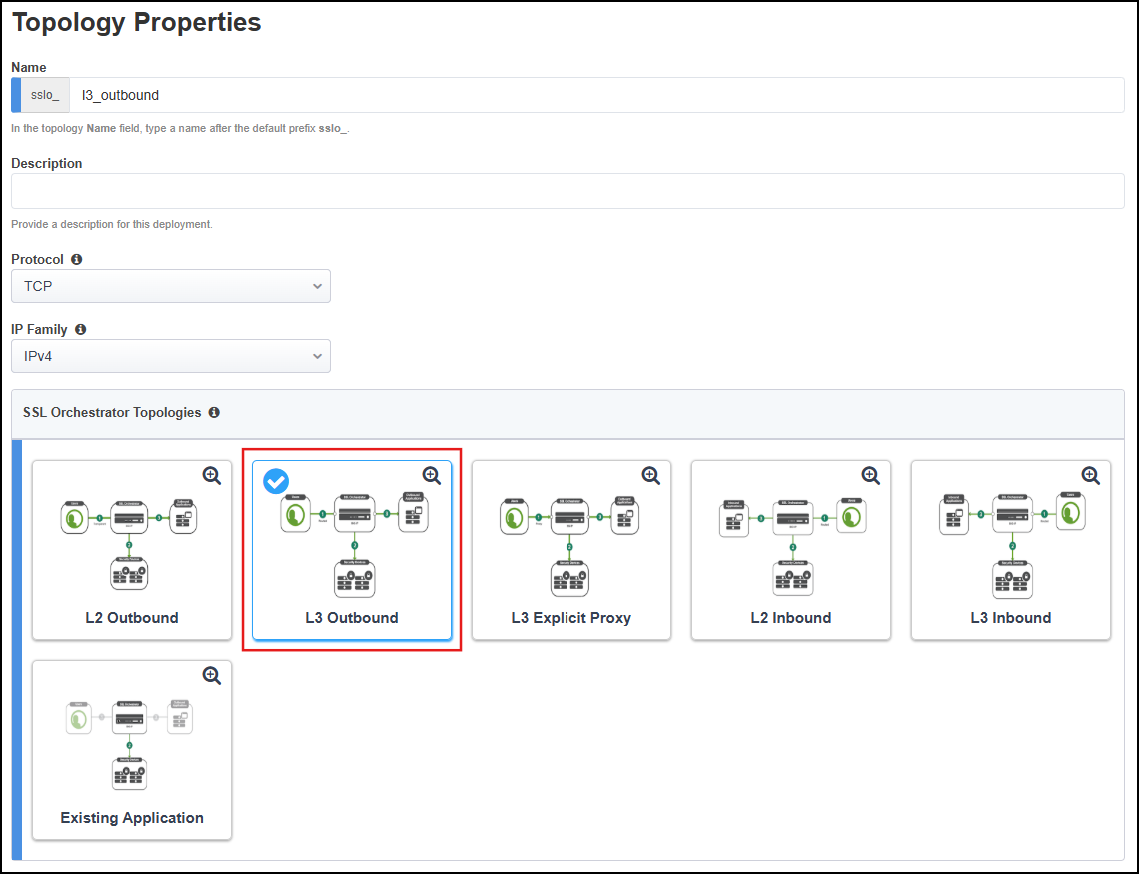
Enter
l3_outboundas the topology name.Select the L3 Outbound topology type.
Scroll down to the bottom of the page and click on the Save & Next button to proceed to the next step in the configuration workflow.
2.3.2. Create SSL Configuration
On the SSL Configurations page, create the Client-side SSL profile for the L3 outbound (transparent) forward proxy.
In the Name field, leave the default value as
l3_outbound.In the Certificate Key Chain section, leave the default settings as is (default certificate and key).
Important
Since this is an outbound forward proxy deployment, the SSL Orchestrator will be using a subordinate CA certificate and private key to sign the re-issued ('forged') certificates delivered to clients for outbound traffic. This is configured in the CA Certificate Key Chains section, not the Certificate Key Chains section.
Note
When using subordinate CA certificates, both the subordinate and root CA certificates must be imported into the client's browser certificate store. The Ubuntu-Client machine in the lab environment trusts has these already installed.
In the CA Certificate Key Chain section, click on the Edit (pencil) icon.
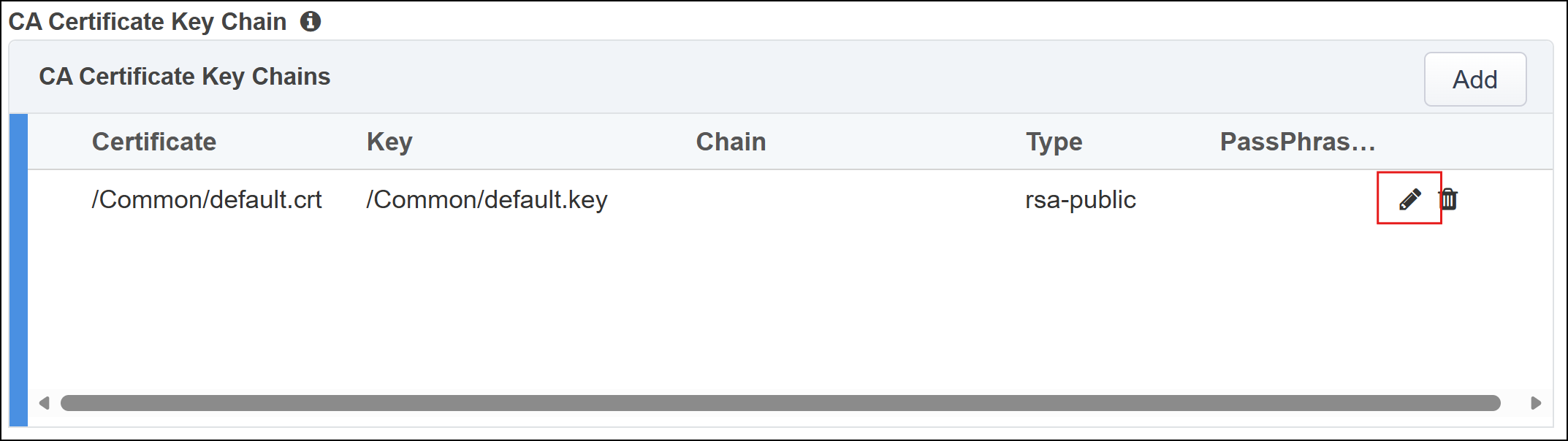
In the Certificate drop-down list, select subrsa.f5labs.com to replace the default value.
In the Key drop-down list, select subrsa.f5labs.com to replace the default value.
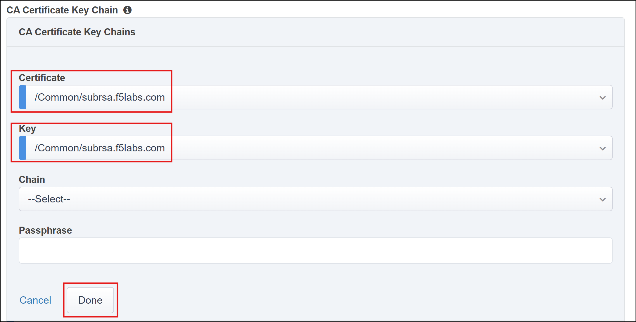
Click on the Done button to apply the config change.
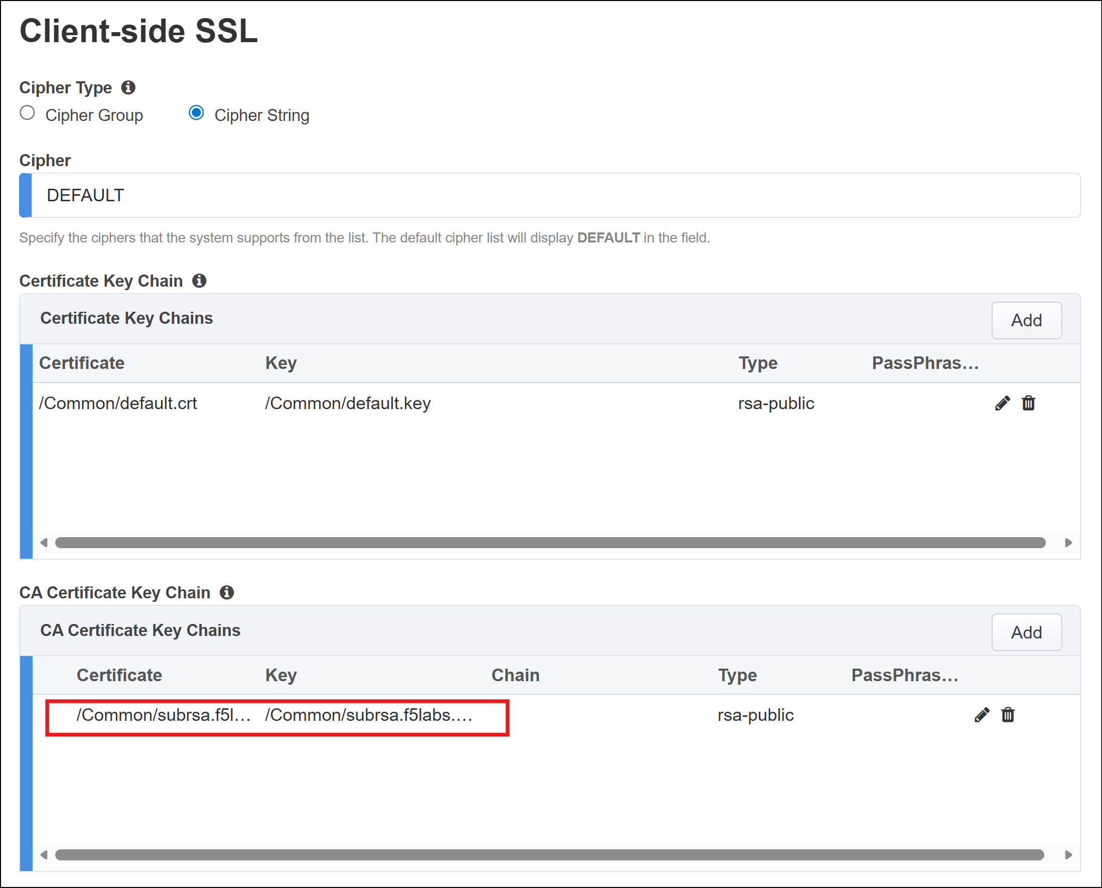
Leave the default Server-side SSL settings.
Click on the Save & Next button to proceed to the next step in the configuration workflow.
2.3.3. Authentication List
No user authentication will be enabled at this time.
Click on the Save & Next button to proceed to the next step in the configuration workflow.
2.3.4. Services List
There will be one Inspection Service ssloS_F5_UC. Recall that this service was created by the SSL Orchestrator User Coaching script.
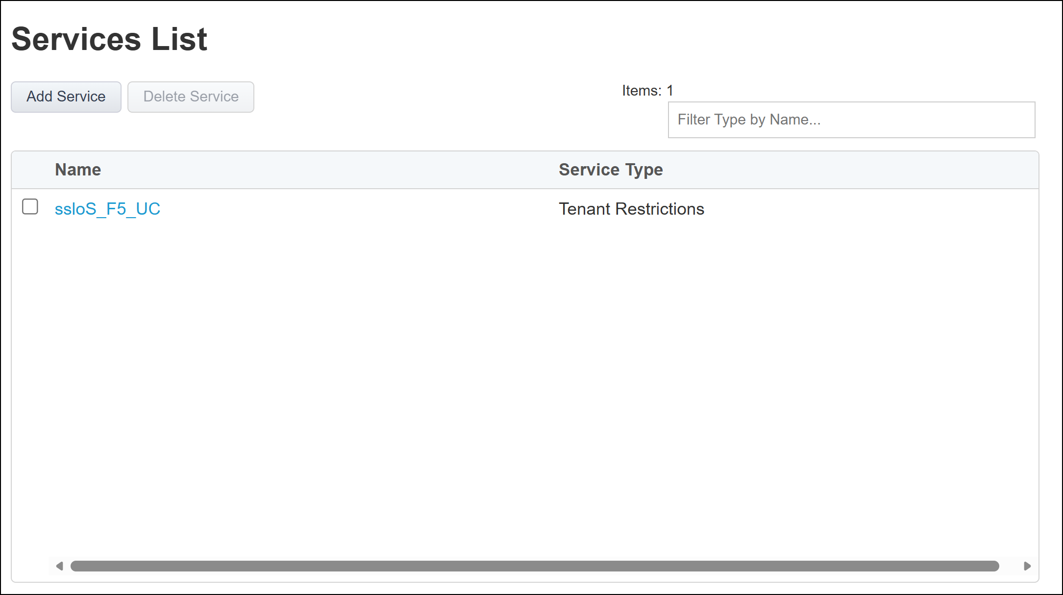
No additional services need to be created at this time.
Scroll down to the bottom of the page and click on the Save & Next button to proceed to the next step in the configuration workflow.
2.3.5. Service Chains List
This section is blank, because we have not yet created any Service Chains. We will create one in a upcoming section to demonstrate the user coaching function.
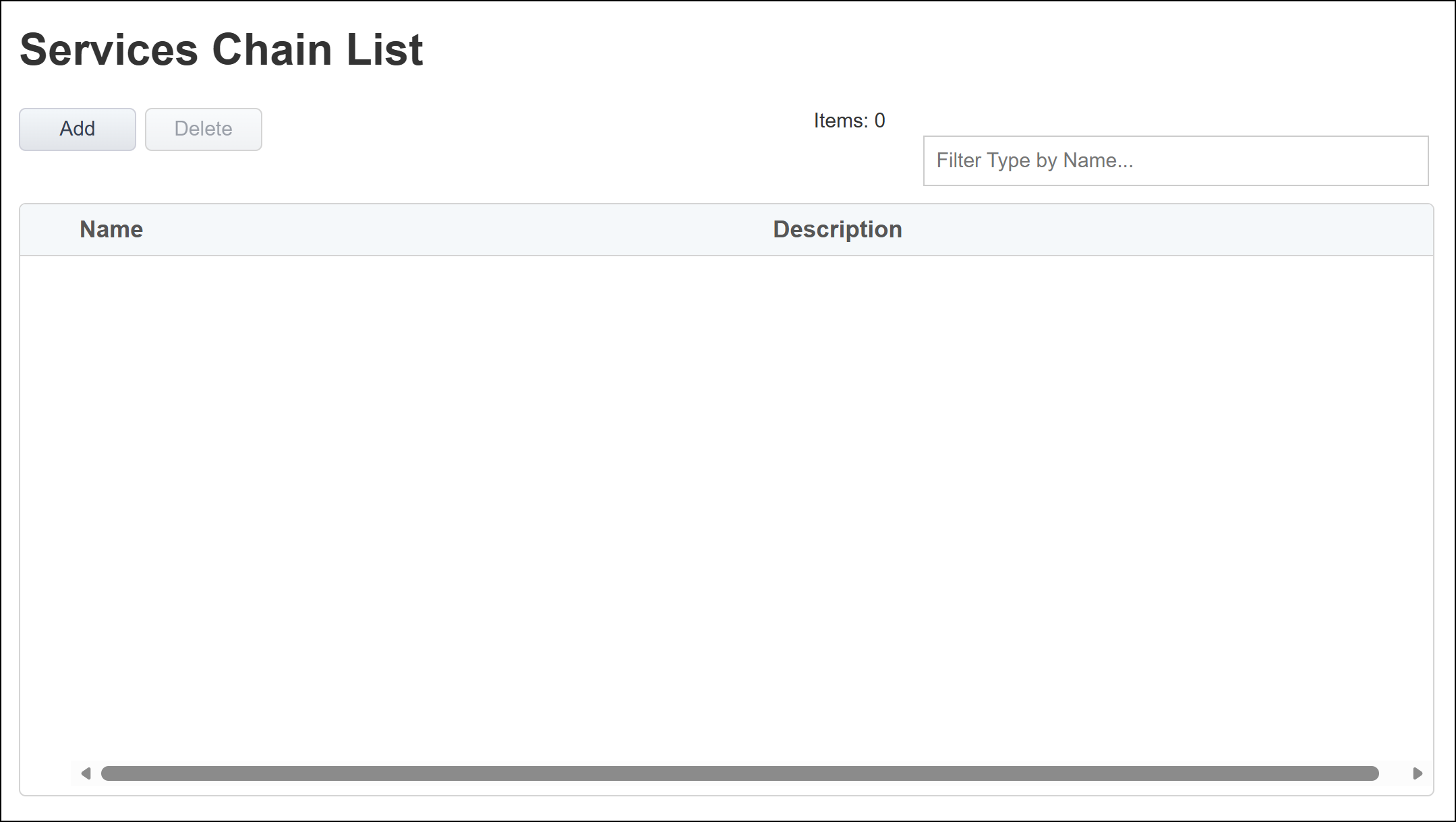
Scroll down to the bottom of the page and click on the Save & Next button to proceed to the next step in the configuration workflow.
2.3.6. Create Security Policy
The Security Policy contains 2 default rules: Pinners_Rule and All Traffic.
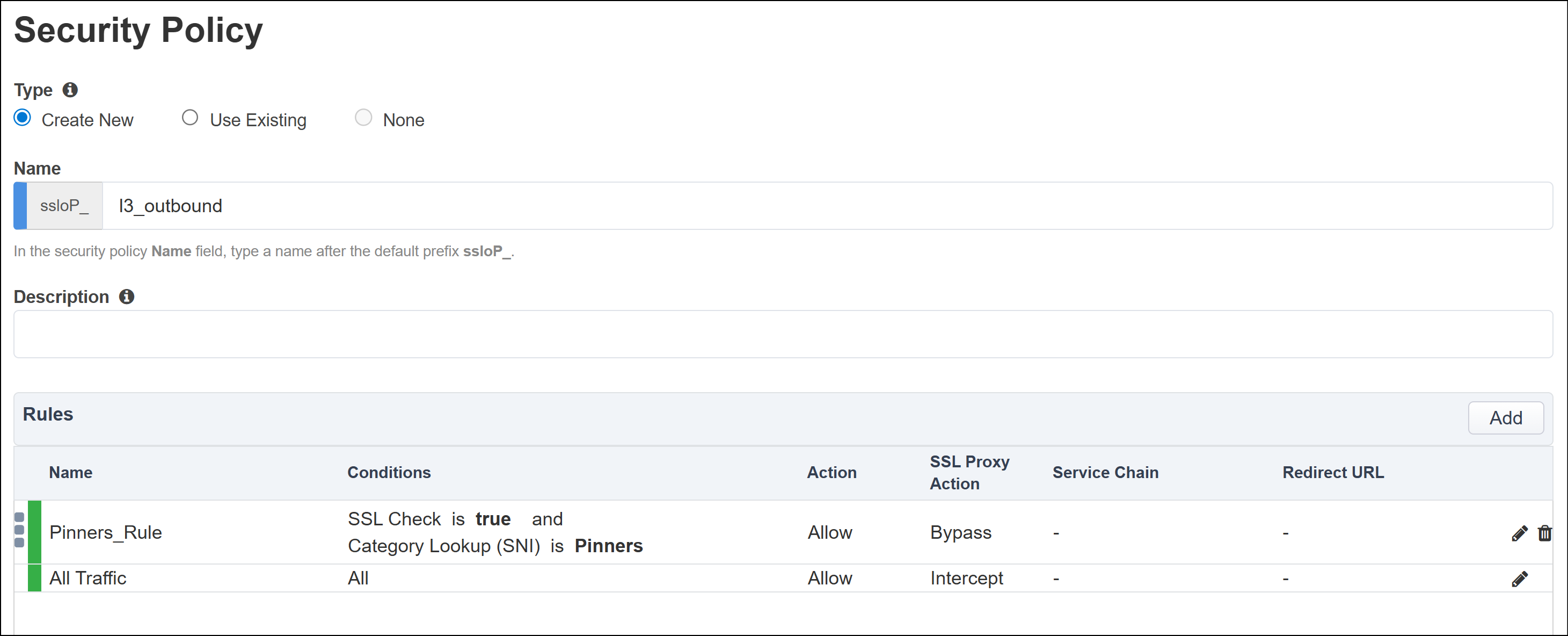
We will not be making any changes to the Security Policy at this time.
Scroll down to the bottom of the page and click on the Save & Next button to proceed to the next step in the configuration workflow.
2.3.7. Create Interception Rule
The Interception Rule determines which traffic to process. For an L3 Outbound topology, you will accept traffic for all destinations and ports.
Leave the default Destination Address/mask value as
0.0.0.0%0/0.Leave the default Port as
0.In the Ingress Network section, select the client-vlan VLAN.
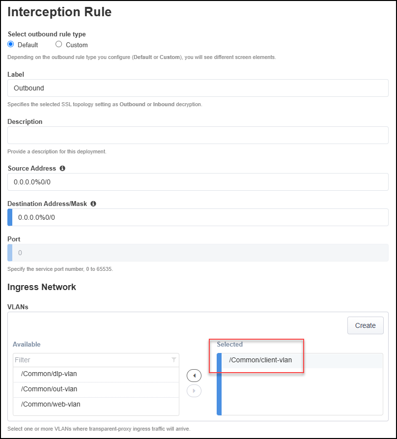
Leave the default values for the remaining sections:
Protocol Settings
Security Policy Settings
Authentication
L7 Interception Rules
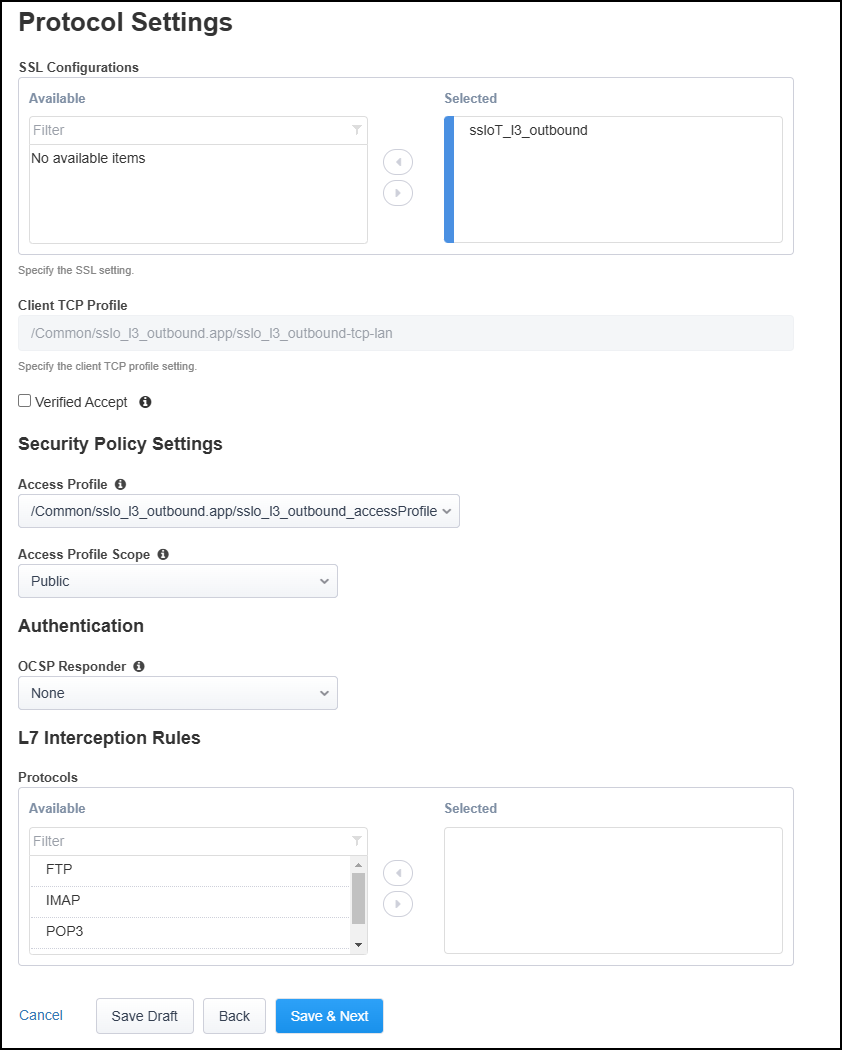
Click on the Save & Next button to continue.
2.3.8. Create Egress Settings
You will use SNAT all egress traffic and use the default route as a gateway.
In the Manage SNAT Settings drop-down list, select Auto Map.
Leave the default Gateways setting.
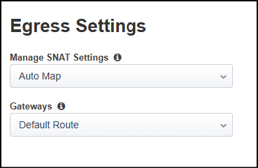
Click on the Save & Next button to continue.
2.3.9. Create Log Settings
Leave the default log settings.
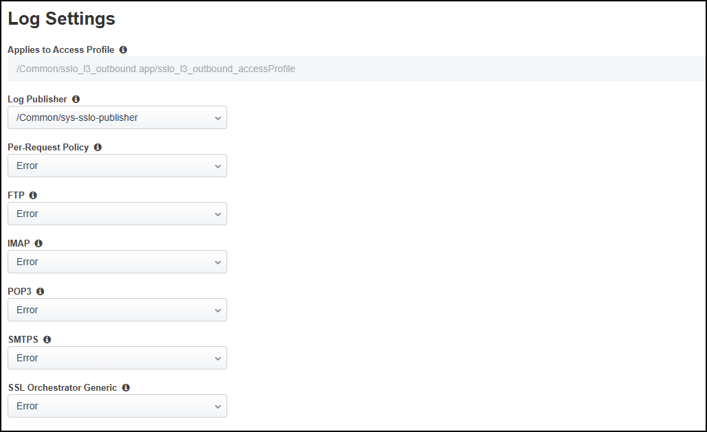
Click on the Save & Next button to continue.
2.3.10. Deploy Topology
Click on the Deploy button to create the new topology configuration.
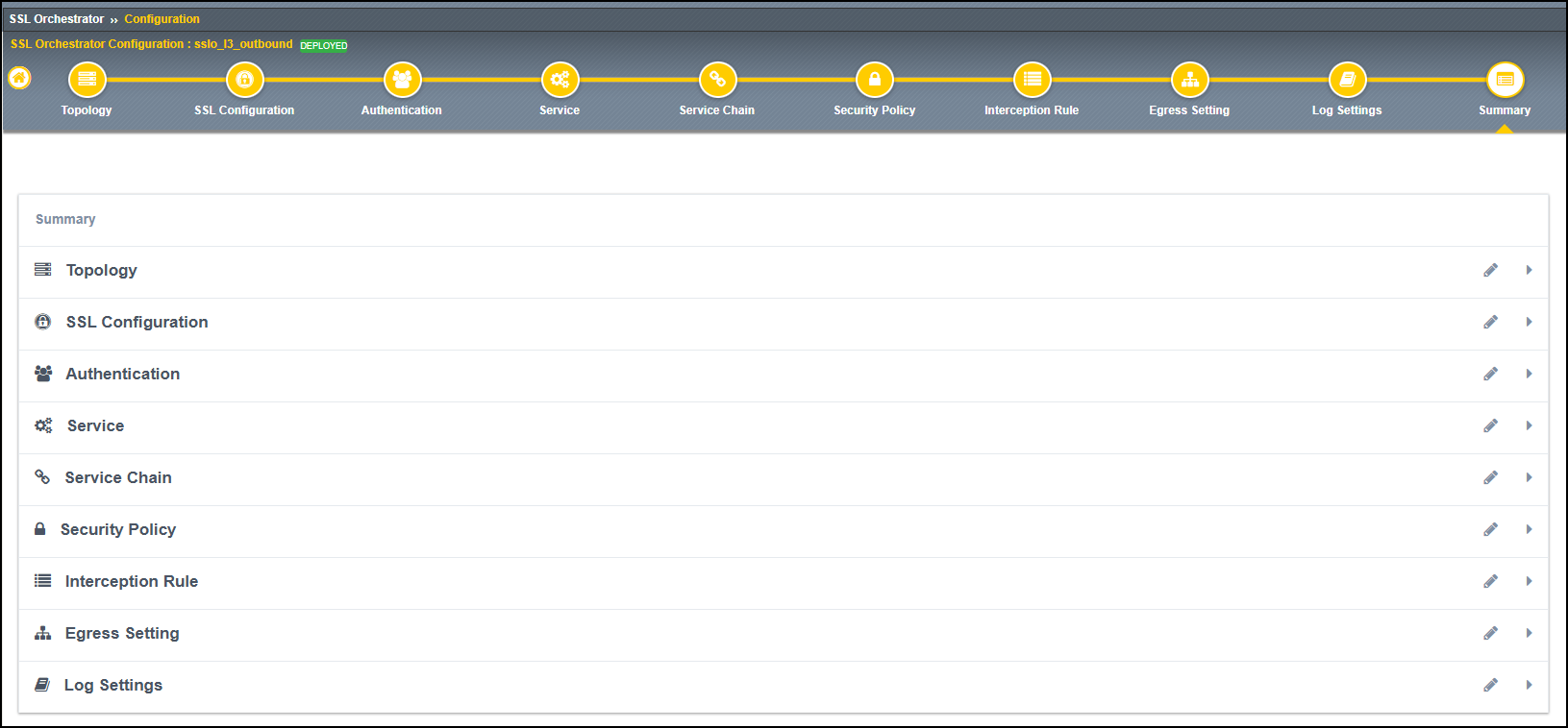
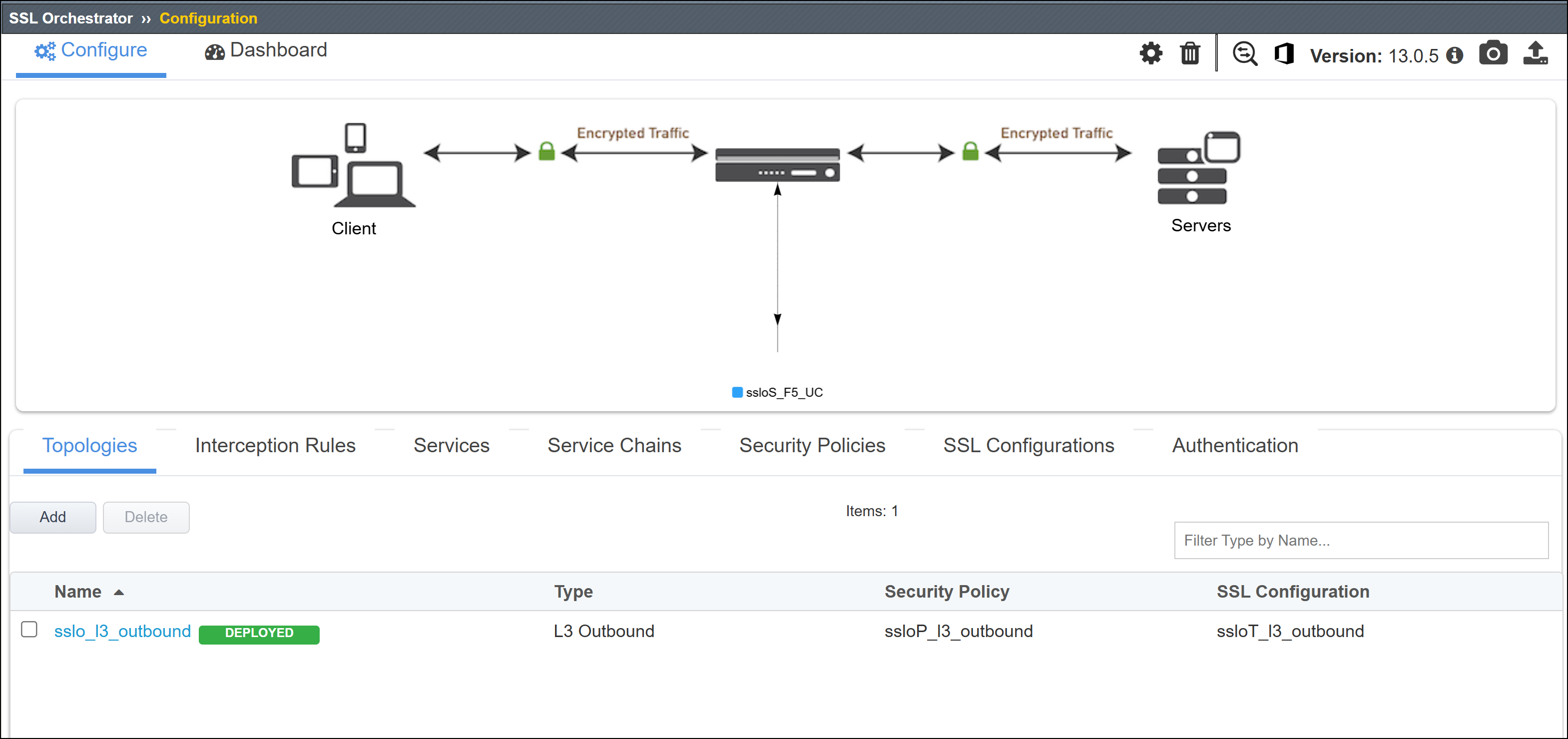
When the deployment has completed, click on the OK button to close the dialog box and return to the Topologies list.