Planning for VELOS Guide Source |
VELOS Networking
Platform Layer Isolation
Management of the new F5OS-C platform layer is completely isolated from in-band traffic networking and VLANs. It is purposely isolated, so that it is only accessible via the out-of-band management network. In fact, there are no in-band IP addresses assigned to either the system controllers or the chassis partitions (The F5OS layer); only tenants will have in-band management IP addresses and access. Tenants also have out-of-band connectivity.
This allows customers to run a secure/locked-down out-of-band management network, where access is tightly restricted. The diagram below shows the out-of-band management access entering the VELOS chassis through the system controllers on the left. The system controllers bridge those external out-of-band connections to an internal out-of-band network, that connects to all chassis partitions and tenants within the VELOS chassis.
Out-of-Band Management Network
All out-of-band networking for VELOS is handled through the system controllers. Each system controller has its own static IP address, and there is also a floating IP address that will follow the active system controller. The system controller will also act as a bridge between the outside out-of-band network, and the out-of-band management VLAN inside the chassis. By default, there is one common network/VLAN for out-of-band networking inside the chassis. All chassis partitions, and tenants will connect to this VLAN, and their default gateway should be pointed to a router on the outside of the chassis. You can attempt to isolate partitions and tenants on the OOB network by using separate IP networks that are multi-netted, but this does not provide true network isolation that a VLAN would provide.
In F5OS-C 1.8.0, 802.1Q VLAN tagging support was added for the out-of-band management ports on VELOS. This new option allows for system controllers, chassis partitions and tenants to be assigned to specific VLANs. This will allow for greater separation on the management VLAN which in previous releases had to be a single shared VLAN. The external ports are configured with specific tagged or untagged VLANs and then those VLANs are presented to the system controllers, partitions, and tenants as untagged, meaning no special configuration is needed to convert to tagged management VLANs inside tenants.
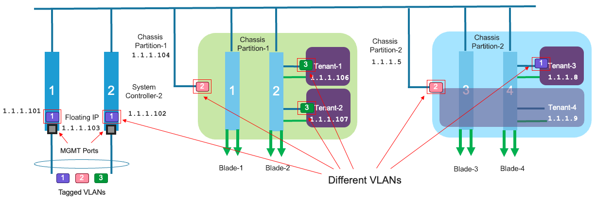
Below is an example deployment; where each system controller has its own unique IP address, and an administrator can connect to either system controller (active/standby) directly, but the standby will be in a read-only mode. It is recommended that a floating IP address be configured, and that IP address will follow the active system controller, so that an admin using the F5OS API, CLI, or webUI can always connect to the active system controller. Note, the individual interfaces on each system controller can be bonded together into a single LAG for added redundancy.
It is recommended to connect both management interfaces from controller-1 and controller-2 to your switching infrastructure for resiliency and for increased bandwidth. Link Aggregation (LAG) is recommended when setting up the system controller management ports. This will provide a better failover/reachability experience as well as double the bandwidth than having both ports connected to an upstream switch in an un-aggregated fashion. When un-aggregated the port on the standby system controller will be put in a blocking mode to prevent a bridge loop from occurring so you will be limited to 10Gb of bandwidth. The internal switchd process monitors the HA status of the local controller and will disable forwarding on the mgmt port if the system controller is in standby mode. If a controller’s mgmt interface goes down, it will fail over to the other system controller and will not assume the active role.
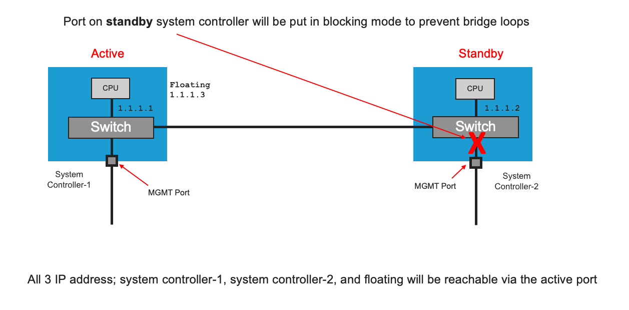
Even though each system controller has a static IP address, they will still both be reachable even if one of the controller mgmt interfaces is down. This is due to the fact that there is an internal switch connecting the two system controllers so they both have equal external connectivity, even if one of the interfaces is down. As an example, if the mgmt interface for controller-2 is disconnected, you might assume that controller-2 would be unreachable via its static IP address. But this is not the case. Since each mgmt port on the system controller is wired internally to a local controlplane switch and the two switches are cross-connected, you can still reach the fixed address of either controller even if only one mgmt interface is available.
You can see this behavior when in an un-aggregated mode by looking at the mgmt interfaces of each controller in F5OS. The example below filters on the properties of interest and uses ‘repeat’ to watch how the counters change.
syscon-2-active# show interfaces interface */mgmt0 state admin-status | select state oper-status | select state counters in-pkts | select state counters out-pkts | repeat 1
        ADMIN   OPER              OUT
NAME     STATUS  STATUS  IN PKTS   PKTS
--------------------------------------------
1/mgmt0  UP      UP      18715364  9974457      <-- out-pkts does not increment while a controller is standby.
2/mgmt0  UP      UP      13286300  3112348
Controller-2 is active, and controller-1 is standby. The mgmt interface on each controller is ‘UP’. While both controllers show incrementing ingress packets, only the active controller shows egress packets incrementing. This is because the front-panel mgmt port on the standby controller has forwarding disabled, so there is no egresses traffic. Yet the standby controller still has full L2 connectivity since its traffic is ultimately carried over the management port of the active controller.
Chassis Partitions and Networking
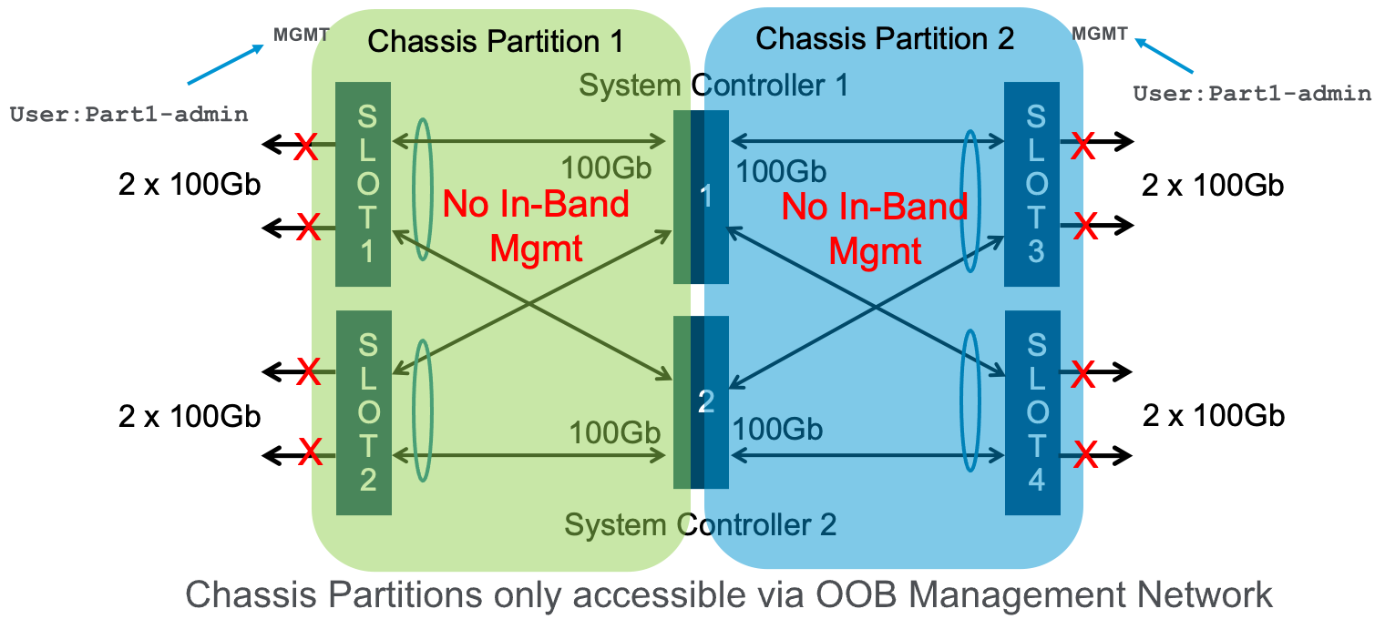
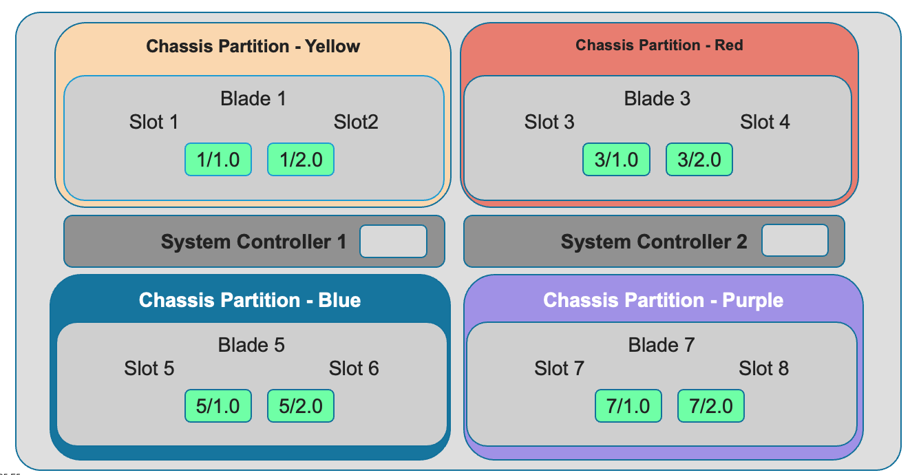
Each chassis partition is a unique entity that has its own set of (local/remote) users and authentication. It is managed via a dedicated out-of-band IP address with its own F5OS CLI, webUI, and API access. A chassis partition can be dedicated to a specific group, and that group will only be able to access networking and tenants within their partition. They will not be able to access or share resources within other chassis partitions in the system. This is an added level of isolation that VIPRION did not have. Below are some examples:
Note: The environment above would require external networking connections between the chassis partitions if a tenant in one chassis partition needed to communicate with a tenant in another chassis partition.
In addition to management access being completely isolated and unique, in-band networking (for use by tenants) is configured and completely contained within the chassis partition. Each chassis partition will have its own set of networking components such as PortGroups, VLANs, LAGs, and interfaces. This means that networking within one chassis partition is not accessible or viewable from another chassis partition.
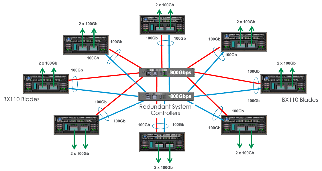
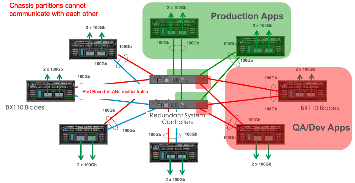
Isolation at the network level is also enforced via the centralized switch fabrics that reside in the dual system controllers. In the VELOS system each blade has multiple connections into the centralized switch fabrics for redundancy and added bandwidth. Each BX110 blade has 2 x 100Gb backplane connections (one to each system controller), that are bonded together in a static LAG (Link Aggregation Group). This star-wired topology provides fast and reliable backplane connections between all the blades and also allows for complete isolation at the networking layer. The same is true with the BX520 blade which has 4 x 100Gb backplane connections (two to each controller).
When chassis partitions are created, the administrator will assign one or more blades, which are then isolated from all other blades in the chassis. The centralized switch fabrics are automatically configured with port based VLANs and VLAN tagging to enforce network isolation between chassis partitions. The diagrams below provide a visual of how this is enforced.
In the example below, the chassis partition Production is completely isolated from the QA/Dev Apps chassis partition.
Network Isolation
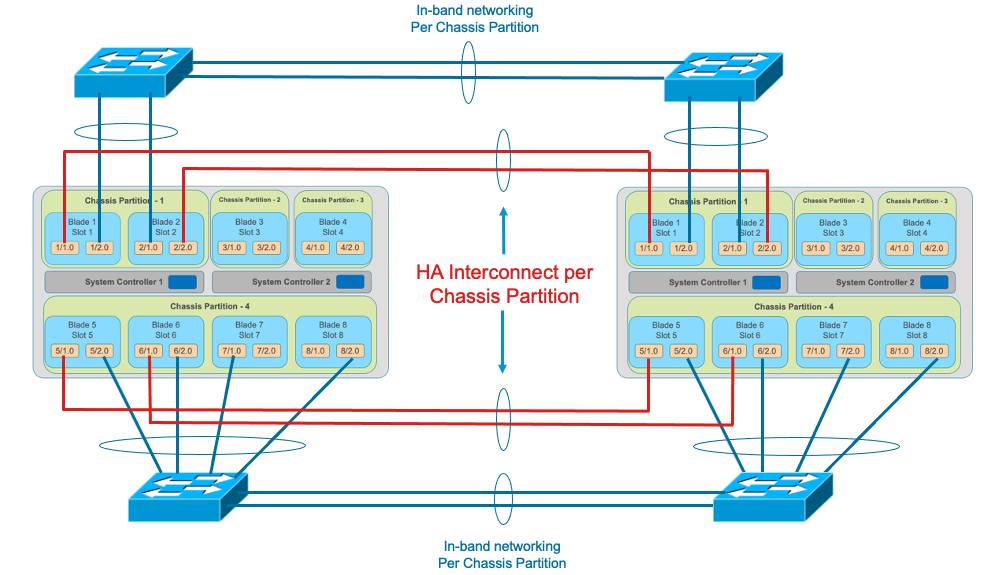
To illustrate the point of how isolated chassis partitions are, the diagram below shows two VELOS chassis with multiple chassis partitions in each. Since there is no sharing of in-band network resources, each chassis partition must have its own network connectivity to the in-band networks, and for optional dedicated HA interconnects between the two chassis. There is no way to share interfaces, VLANs, or LAGs between chassis partitions.
Port Groups
The portgroup component is used to control the mode of the physical port. This controls whether the port is bundled or unbundled, and the port speed. The term portgroup is used rather than simply “port” because some front panel ports may accept different types of optics. Depending on the portgroup mode value, a different FPGA version is loaded, and the speed of the port is adjusted accordingly. The user can modify the portgroup mode as needed through the F5OS CLI, webUI, or API.
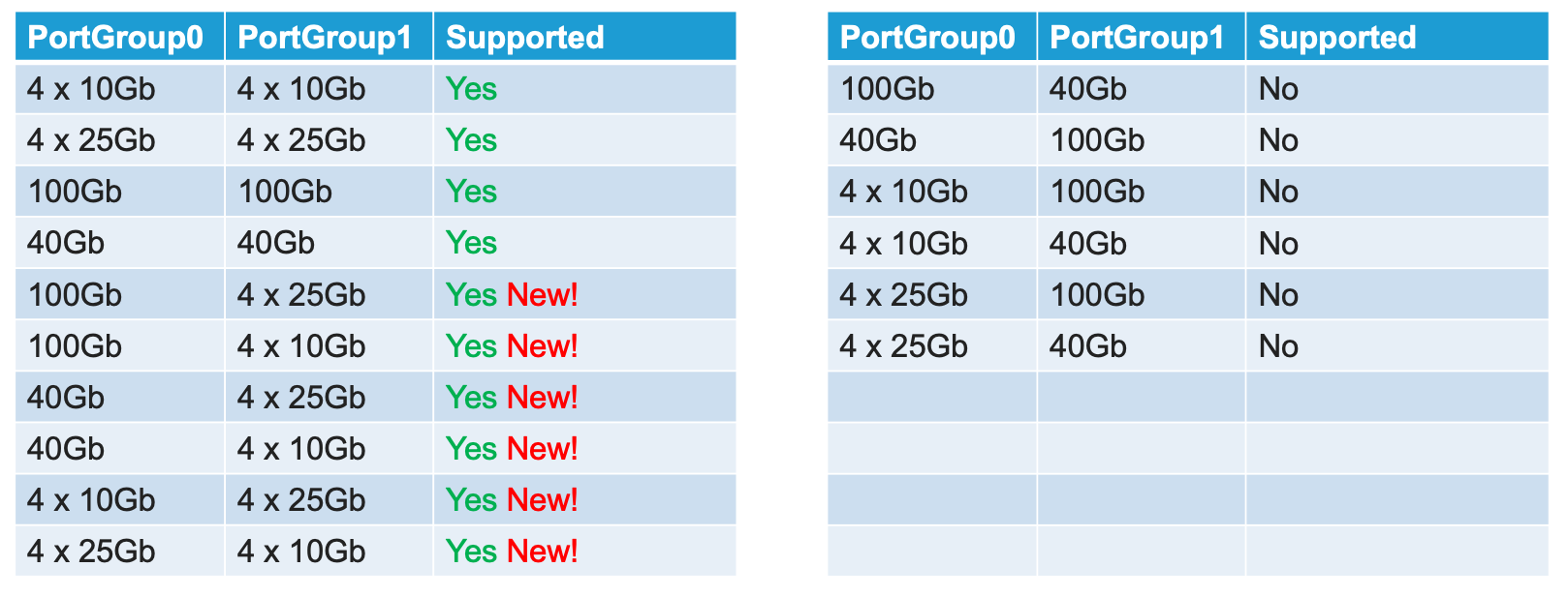
In releases prior to F5OS-C 1.5.1 both ports on a BX110 blade must be configured for the same mode, both ports must be either 100GB, 40GB, 4 x 25GB, or 4 x 10GB; there was no support for mixing modes on the same blade. You could have different options across different blades within the same chassis partition, but within a single blade, the ports had to be the same. F5OS-C 1.5.1 introduced more flexible options for port group configurations within the same blade. The table below shows the new heterogeneous port modes that were introduced in F5OS-C 1.5.1.
Below is an example of the chassis partition webUI Port Groups screen with BX110 blades. Note that any changes in configuration will require a reboot of the blade to load a new FPGA bitstream image.

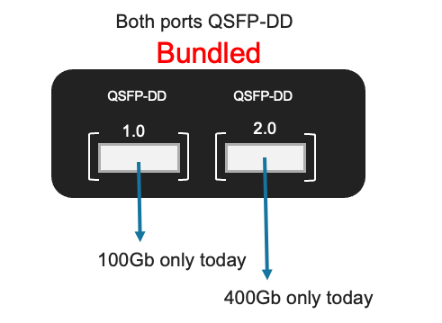
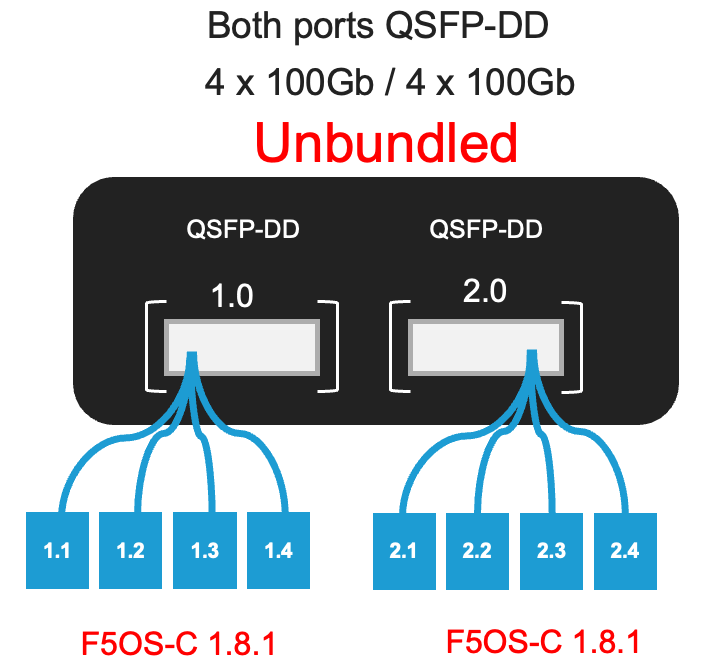
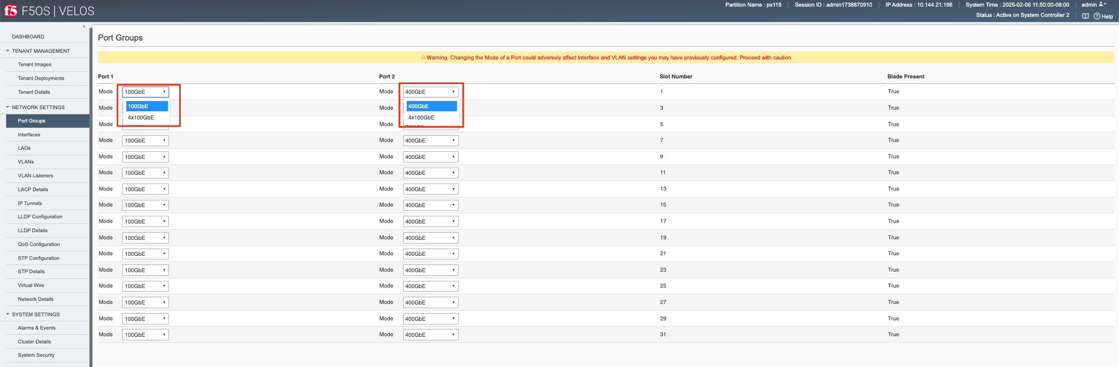
For the BX520 blade there are two physical ports (1.0 & 2.0). Port 1.0 is a QSFP-DD port, that supports either 100Gb optics or 4 x 100Gb (targeted to be generally available F5OS-C 1.8.1 release) connections with the proper optic and breakout cable. For the current release, 100Gb connectivity (SR-4 & LR-4) is supported, 4 x 100Gb support is targeted to be generally available in a the F5OS-C 1.8.1 release. The second port (2.0) is also a QSFP-DD port; however it supports 400Gb optics today (FR-4), and the option of 4 x 100Gb with the proper optic and breakout cables is targeted to be generally available in the F5OS-C 1.8.1 release.
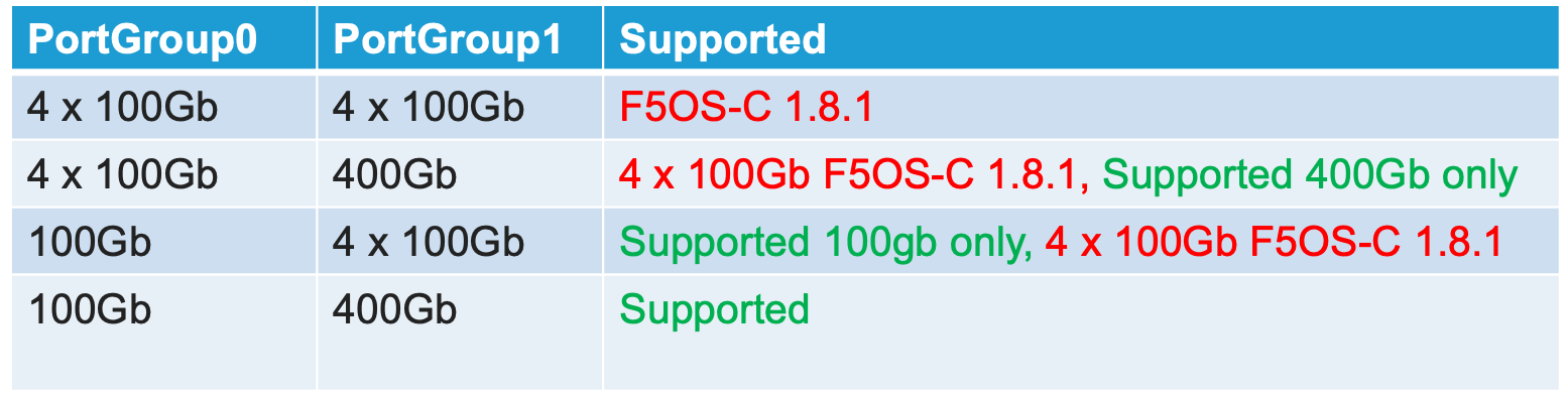
Below is an example of the chassis partition webUI Port Groups screen with BX520 blades. Note that any changes in configuration will require a reboot of the blade to load a new FPGA bitstream image. Port1 is currently hardcoded for 100Gb, and port2 is currently hard coded at 400gb. Breakout support for 4 x 100Gb is targeted to be generally available in F5OS-C 1.8.1.
Interfaces
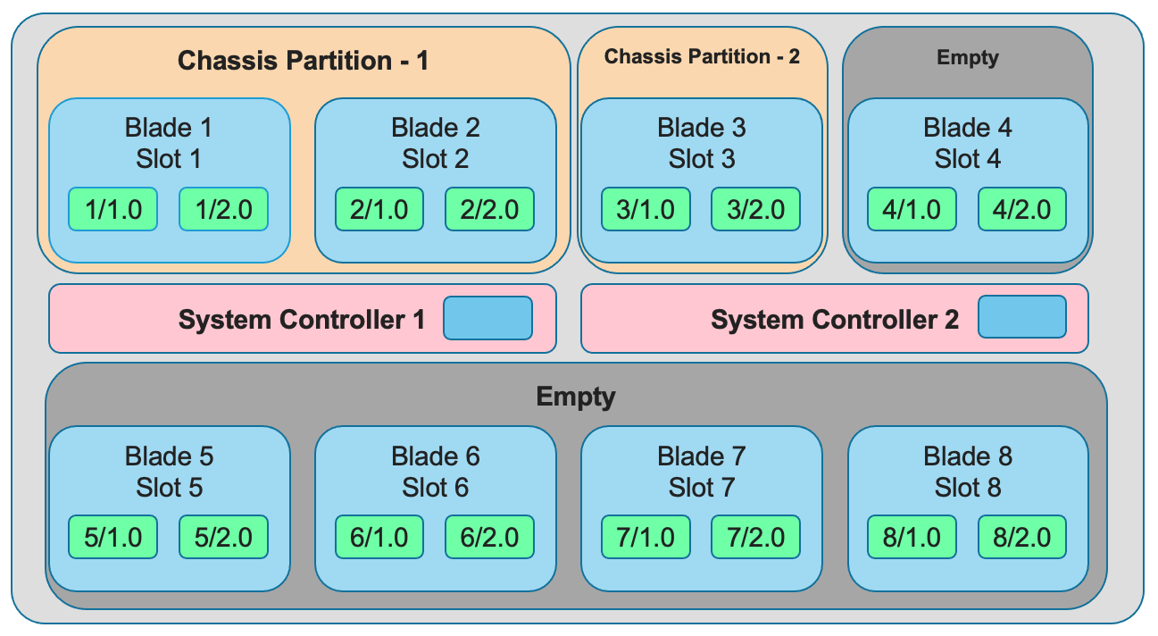
Interface numbering will vary depending on the current portgroup configuration. Interfaces will always be numbered by <blade#>/<port#>. The number of ports on a blade will change depending on if the portgroup is configured as bundled, or unbundled. If the ports are bundled then ports will be 1/1.0 and 1/2.0 for slot 1, and 2/1.0 and 2/2.0 for slot 2.
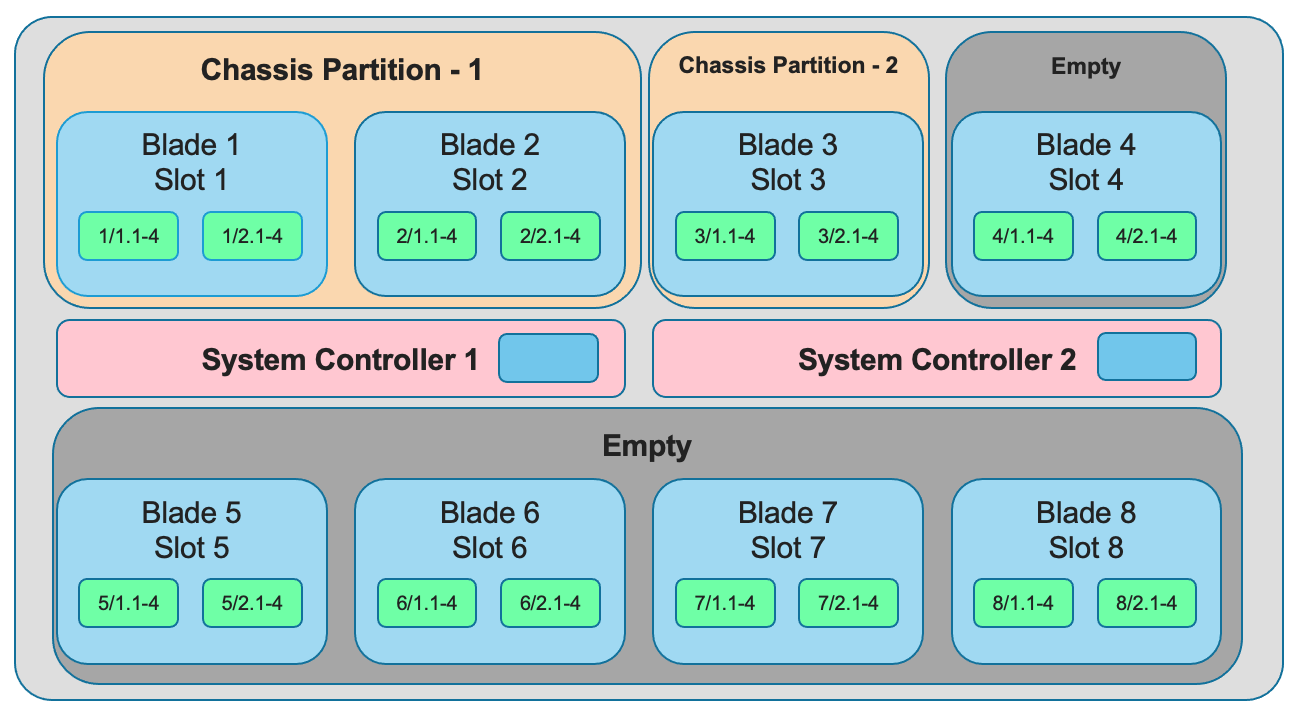
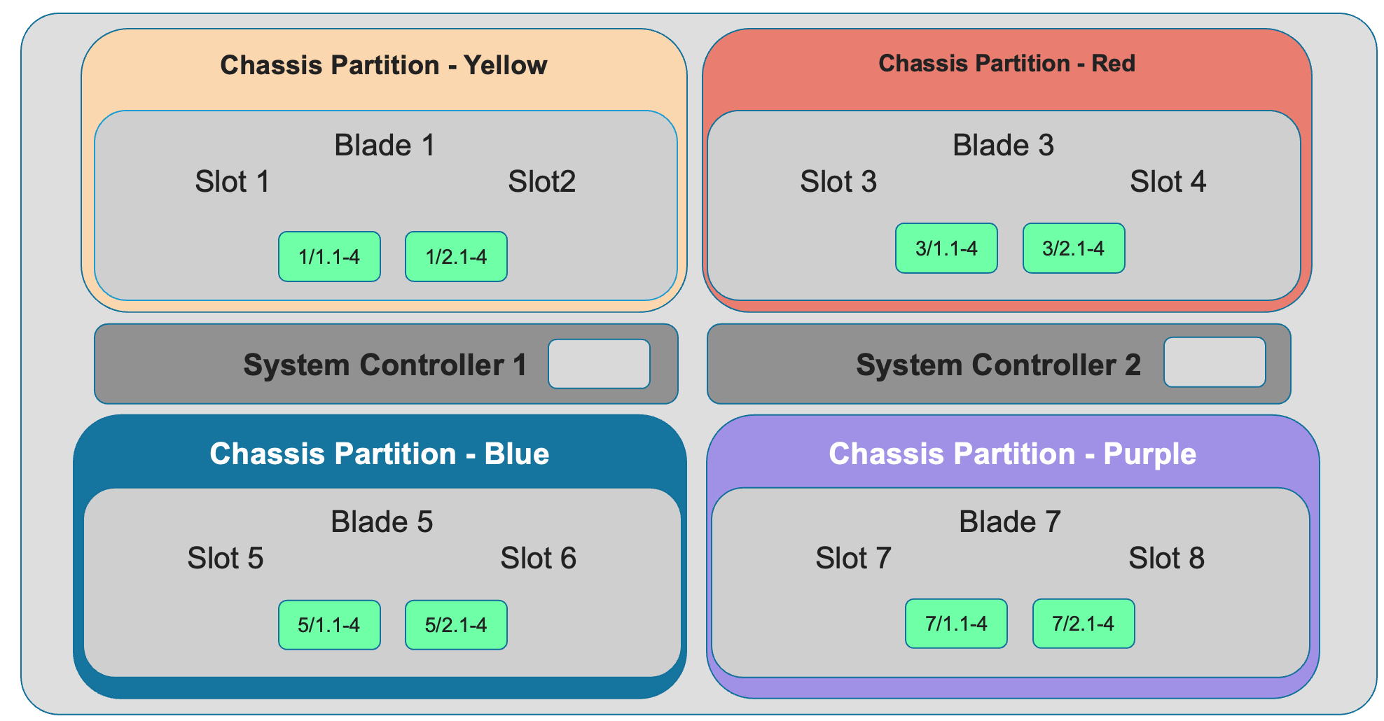
If ports are unbundled, then the port numbering will be 1/1.1, 1/1.2, 1/1.3, and 1/1.4 for the first physical port and 1/2.1, 1/2.2, 1/2.3, and 1/2.4 for the second physical port. Breakout cables will be needed to support the unbundled 25Gb, or 10Gb configurations. Even when multiple chassis partitions are used, the port numbering will stay consistent starting with the blade number. Below is an example of BX110 blade port numbering when all interfaces are bundled.
Below is an example of BX110 port numbering when all interfaces are unbundled.
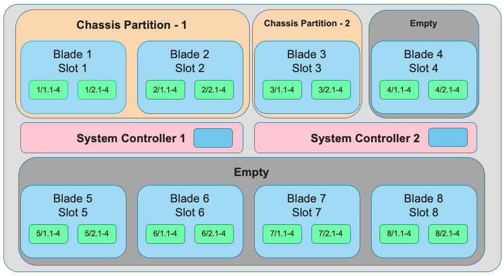
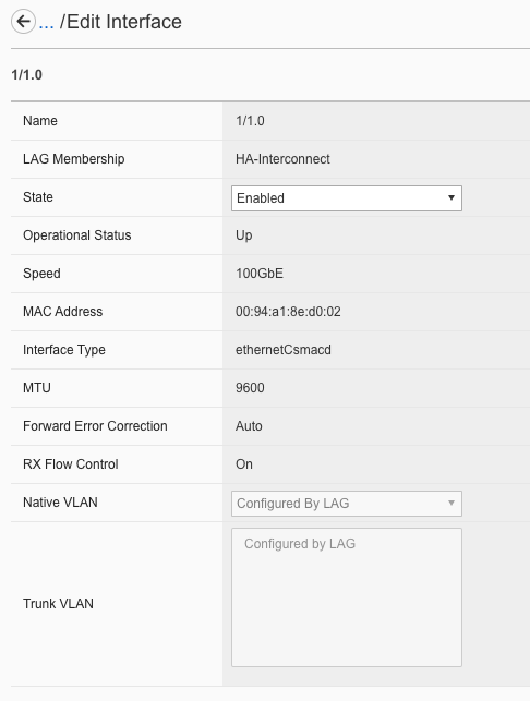
For the BX520 blades interface numbering is different because the BX520 blade takes up two slots. The slot reference for the blade will always be the first of the two slots where the blade is inserted, which will always be an odd number. If the ports are bundled, then ports will be 1/1.0 and 1/2.0 for a blade that occupies slot 1 and slot 2, and 3/1.0 and 3/2.0 for a blade that occupies slots 3 and 4. Below is an example of four BX520 blades within the CX410 chassis and their interface numbering when all ports are bundled.
Below is an example of BX520 port numbering when all interfaces are unbundled into 4 x 100gb interfaces.
Supported Optics
Only F5 branded optics are officially supported on VELOS per F5’s third party hardware components policy. The BX110 blade supports speeds of 40Gb and 100Gb as well as 4 x 10Gb and 4 x 25Gb through the use of breakout cables. You must have the proper optic type inserted (and optional breakout cables) as well as the proper port group configuration for links to be established. The BX520 blade supports speeds of 400Gb or 4 x 100Gb (with proper breakout cable). VELOS interfaces will accept F5 approved QSFP+, QSFP28, or QSFP-DD optics depending on the blade type. 3rd party optics are not officially supported per F5’s support policies:
K8153: F5 support of third-party hardware components
More details on each optic can be found in the F5 Platforms Accessories guide & in the solution article below:
BX110 40Gb QSFP+ options:
| 40GBASE-LR4 (QSFP+) | OPT-0030 | TRANSCEIVER, QSFP+, 40G-LR4, 10KM, LC, SMF, DDM, F5 BRANDED |
| 40GBASE-SR4 (QSFP+) | OPT-0036 | TRANSCEIVER, QSFP+, 40GIG-SR4, 850NM, 100M, MPO, RESET, MMF, DDM, F5 BRANDED |
| 40G-PSM4 (QSFP+) | OPT-0045 | TRANSCEIVER, QSFP+, 40GIG-PSM4, 1310NM, 10KM, MPO, SMF, DDM, F5 BRANDED |
BX110 Dual Rate 40Gb/100Gb BiDi QSFP28 (Backward compatible with QSFP+):
The transceiver below can be used in QSFP28 or QSFP+ slots, or as 40G QSFP+ in QSFP28 slot.
Note
The OPT-0060 SKU (40G/100G dual rate BiDi) below replaces the previous OPT-0043 SKU (40G BiDi).
| Dual Rate 40G/100G BIDI (QSFP28 backward compatible with QSFP+) | OPT-0060 | VELOS Field Upgrade Transceiver QSFP28/QSFP+, dual rate 40G/100G SR BIDI, 100M, LC, MMF |
BX110 100Gb QSFP28 options:
| 100GBASE-SR4 (QSFP28) | OPT-0031 | TRANSCEIVER, QSFP28, 100G-SR4, 850NM, MMF, MPO, DDM, BRANDED |
| 100GBASE-LR4 (QSFP28) | OPT-0052 | TRANSCEIVER, QSFP28, 100G-LR4, 10KM, LC, SMF, 4.5W, DDM, VELOCITY SDK, BRANDED |
| 100G-PSM4 (QSFP28) | OPT-0055 | TRANSCEIVER, QSFP28, 100GIG-PSM4, 1310NM, 500M, MPO, SMF, F5 BRANDED |
Note: OPT-0039 QSFP28 LR4 used in VIPRION/iSeries are compatible with VELOS, but default optics for 100G LR4 VELOS is OPT-0052 (as shown above).
BX520 400Gb QSFP-DD options:
The optics below are only supported on the BX520 blade. 400Gb optics are not supported on the BX110 blade.
| 400GBASE-FR4 (QSFPDD) | OPT- | TRANSCEIVER, QSFPDD, (400G-FR4 1310NM, 2KM, LC, SMF, DDM Support) |
| 400GBASE-DR4 (QSFPDD) | OPT- | TRANSCEIVER, QSFPDD, (400G-DR4+ 1310NM, 2KM, MPO-12, SMF, DDM Support) |
| 400GBASE-LR4 (QSFPDD) | OPT- | TRANSCEIVER, QSFPDD, (400G-LR4 13xxNM, 10KM, LC, SMF, DDM Support) |
| 400GBASE-BDSR42 (QSFPDD) | OPT- | TRANSCEIVER, QSFPDD (400G-SR4.2 BiDi, 150M OM5, MPO-12, MMF) |
Below are the current VELOS optic SKUs:
Note
Some older SKU’s may operate in VELOS, but are no longer available to purchase. They are listed in the following document.
| F5-UPGVELQSFP28LR4 | VELOS Field Upgrade: QSFP28 Transceiver (100G-LR4, 10KM, LC, SMF, DDM) ROHS | F5-UPG-QSFP28-LR4 (OPT-0039-01) - QSFP28 TRANSCEIVER (100G-LR4, 10KM, LC, SMF, 4.5W, DDM) |
| F5-UPGVELQSFP28PSM4 | VELOS Field Upgrade: QSFP28 Transceiver (100G-PSM4, 500M, MPO/APC, SMF, DDM) ROHS | F5-UPGVELQSFP28PSM4 (OPT-0055-01) - QSFP28 TRANSCEIVER (100G-PSM4, 1310nm, 500M, MPO/MTP, DDM) |
| F5-UPGVELQSFP28-SR4 | VELOS Field Upgrade: QSFP28 Transceiver (100G-SR4, 100M, MPO MMF, DDM) ROHS | F5-UPG-QSFP28-SR4 (OPT-0031-01) - QSFP28 TRANSCEIVER (100G-SR4, 850NM, 100M, MMF, MPO, DDM) |
| F5-UPG-VELQSFP28SRBD | VELOS Field Upgrade Transceiver QSFP28/QSFP+, dual rate 40G/100G SR BIDI, 100M, LC, MMF | F5-UPG-QSFP28-SRBD (OPT-0060-XX) - QSFP28 TRANSCEIVER (100G BIDI, 850-910 nm, 100M, MMF, Duplex LC, DDM) |
| F5-UPG-VEL-QSFP+LR4 | VELOS Field Upgrade: QSFP+ Transceiver (40G-LR, 1310NM, 10KM, LC, SMF, DDM Support) | F5-UPG-QSFP+LR4 (OPT-0030-01) - 40GBase-LR4 10km QSFP+ 40G Transceiver with DDM Support |
| F5-UPG-VEL-QSFP+PSM4 | VELOS Field Upgrade: QSFP+ Transceiver (40G-PSM4, 1310NM, 10KM, MPO/APC, SMF, DDM ) | F5-UPG-QSFP+PSM4 (OPT-0045-01) - 40GBase-LR-PSM4 QSFP+ 4x10LR PSM4 40G Transceiver with DDM Support |
| F5-UPG-VEL-QSFP+SR4 | VELOS Field Upgrade: QSFP+ Transceiver (40G-SR4, 850NM, 100M, MPO, DDM Support) | F5-UPG-QSFP+SR4 (OPT-0036-01) - 40GBase-SR4 100m QSFP+ 40G Transceiver with DDM Support |
| F5-UPGVELQSFP28LR4B | VELOS Field Upgrade: QSFP28 Transceiver (100G-LR4, 10KM, LC, SMF, DDM) | F5-UPGVELQSFP28LR4B (OPT-0052-01) - QSFP28 TRANSCEIVER (100G-LR4, 1295-1310 nm, 10KM, LC, SMF, DDM) |
| F5-UPG-VELQSFP28LRSL | VELOS Field Upgrade: QSFP28 Transceiver (100G-LR Single Lambda, 10KM, LC, SMF, DDM Support) | F5-UPG-QSFP28-LR-SL (OPT-0061-01) - TRANSCEIVER, QSFP28, 100G, LR, SINGLE LAMBDA, 10KM, LC UPC, SMF, F5 BRANDED |
| F5-UPG-VEL-QSFP28-DR | Field Upgrade: QSFP28 Transceiver (100G-DR Single Lambda, 500M, LC, SMF, DDM) (rSeries ONLY) | F5-UPG-QSFP28-DR (OPT-0062-01) - TRANSCEIVER, QSFP28, 100G, DR, SINGLE LAMBDA, 500M, LC UPC, SMF, F5 BRANDED |
| F5-UPG-VEL-QDD-DR4+ | VELOS Field Upgrade: QSFP-DD Transceiver (400G-DR4+ 1310NM, 2KM, MPO-12, SMF, DDM Support) | |
| F5-UPG-VEL-QDD-FR4 | VELOS Field Upgrade: QSFP-DD Transceiver (400G-FR4 1310NM, 2KM, LC, SMF, DDM Support) | |
| F5-UPG-VEL-QDD-LR4 | VELOS Field Upgrade: QSFP-DD Transceiver (400G-LR4 13xxNM, 10KM, LC, SMF, DDM Support) | |
| F5-UPG-VEL-QDDBDSR42 | VELOS Field Upgrade: QSFP-DD Transceiver (400G-SR4.2 BiDi, 150M OM5, MPO-12, MMF) | |
| F5-UPG-VEL-QSFP28-FR | VELOS Field Upgrade: QSFP28 Transceiver (100G-FR Single Lambda, 2KM, LC, SMF, DDM Support) | |
| F5-UPG-VELQSFP28SR12 | VELOS Field Upgrade: QSFP28 Transceiver (100G-SR1.2 BiDi, 150M OM5, LC, MMF) |
The QSFP+ and QSFP28 optics when configured for unbundled mode, will break out into either 4 x 25Gb (with a 100Gb QSFP28 optic) or 4 x 10Gb (with a 40Gb QSFP+ optic). You will need to utilize a breakout cable to allow the single physical port to break out into 4 lower speed ports. The following breakout cable SKUs can be ordered and utilized on the BX110 blade for either 4 x 25Gb, or 4 x 10GB depending on the optic installed. Note, they come in different lengths (1 meter, 3 meters, or 10 meters) and each of the SKUs is a 2 Pack.
| F5-UPGVELSR4XSR3M | VELOS Field Upgrade: QSFP28-QSFP+ Breakout Cable for SR4 ONLY MPO to 4LC (3 Meter 2 Pack) |
| F5-UPGVELSR4XSR1M | VELOS Field Upgrade: QSFP28-QSFP+ Breakout Cable for SR4 ONLY MPO to 4LC (1 Meter 2 Pack) |
| F5-UPGVELSR4XSR10M | VELOS Field Upgrade: QSFP28-QSFP+ Breakout Cable for SR4 ONLY MPO to 4LC (10 Meter 2 Pack) |
Breakout for 40G PSM4 or 100G PSM4 transceivers ONLY (Note these are not 2 pack):
| F5-UPG-VELPSMXLR10M | VELOS Field Upgrade: QSFP28-QSFP+ Breakout Cable for PSM4 ONLY. MPO/APC to 4LC (10 Meter) |
| F5-UPG-VELPSM4XLR3M | VELOS Field Upgrade: QSFP28-QSFP+ Breakout Cable for PSM4 ONLY. MPO/APC to 4LC (3 Meter) |
Below are the breakout cables for the BX520 QSFP-DD (400Gb) ports to support 4 x 100Gb connectivity. The QSFP-DD optics when configured for unbundled mode will break out into or 4 x 100Gb (with a 400Gb QSFP-DD optic). You will need to utilize a breakout cable to allow the single physical port to break out into 4 lower speed ports. The following breakout cable SKUs can be ordered and utilized on the BX520 blade for 4 x 100Gb connectivity. Note, they come in different lengths (3 meters, or 10 meters).
| F5-UPG-VEL-QDD-4X-3M | VELOS Field Upgrade: QSFP-DD Breakout Cable 400G to 4x100G, MPO-12 to 4LC (3 Meter) |
| F5-UPG-VEL-QDD-4X10M | VELOS Field Upgrade: QSFP-DD Breakout Cable 400G to 4x100G, MPO-12 to 4LC (10 Meter) |
VLANs
VELOS supports both 802.1Q tagged and untagged VLAN interfaces. In the current F5OS releases, double VLAN tagging (802.1Q-in-Q) is not supported. Any port within a chassis partition, even across blades can be added to a VLAN, and VLANs are specific to that chassis partition. VLAN IDs (which may or may not be the same logical VLAN) can be re-used across different chassis partitions, and tenants within a chassis partition can share the same VLANs. Any VLANs that are configured on different chassis partitions will not be able to communicate inside the chassis, they will need to be connected via an external switch to facilitate communication between them.
Link Aggregation Groups
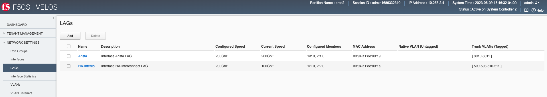
VELOS allows for bonding of interfaces into Link Aggregation Groups or LAGs. LAGs can span across blades, as long as blades are in the same chassis partition. Links within a LAG must be the same type and speed. LAGs may be configured for static or lacp mode. The maximum number of members within a single LAG is 32.
An admin can configure the LACP Type to LACP or Static, the LACP Mode to be Active or Passive, and the LACP Interval to Slow or Fast.