Enabling Egress Traffic Using SNAT
Learn how to enable egress traffic from pods specified in the watchNamespace value when installing the SPK Controller.
This guide walks through configuration options when enabling egress traffic on pods deployed to the watchNamespace namespaces.
Important
Egress traffic being proxied through f5-tmm from namespaces watched by f5ingress are disabled by default.
Note
The SPK Controller contains multiple pods. We will refer to the controller pod as f5ingress.
Overview
We will be detailing how to enable egress traffic from pods in the namespaces watched by f5ingress by using one of the standard Service Proxy for Kubernetes (SPK) Custom Resource Definitions (CRD), f5-spk-egresses.k8s.f5net.com.
On a standard Kubernetes cluster, a pod’s egress traffic going outside the cluster is handled by the default network CNI. Some examples of CNI networks are Flannel or Calico for a generic Kubernetes cluster or ovn-kubernetes for OpenShift. This guide assumes you are using ovn-kubernetes on OpenShift. When egress traffic from a pod need to reach an external source outside the cluster, the network CNI will typically SNAT that traffic using the node IP where the pod is deployed. So if egress traffic from a pod deployed to, say, worker-1 with a management IP address of, say, 192.168.1.10, the cluster’s network CNI will SNAT outgoing traffic using IP address 192.168.1.10 as the source IP.
But when the SPK Controller is installed specifying the namespaces to watch, all egress traffic from pods in that namespace will get proxy through the f5-tmm pod instead of the default network CNI. And by default, the f5-tmm pod is not configured to enable egress traffic. The config to enable this is by creating a f5-spk-egresses Custom Resource (CR). This allows the administrator to enable egress (outbound) traffic via Source Network Address Translation (SNAT) rule on f5-tmm. Once that is configured properly, pods in the watch namespaces will now be able to initiate egress traffic. There are a couple SNAT options that can be configured:
SNAT Automap
SNAT Pools
When an application from the namespaces watched by SPK makes an outbound request, the source IP is translated to either a Self-IP address configured with f5-spk-vlan CRs or one of the available IP addressees in a SNAT Pool configured with f5-spk-snatpool CRs. This ensures all returning inbound responses are routed to the application through the same outbound path, which is through f5-tmm. Additional configuration details for the IngressRouteSnatpool and F5SPKVlan can be found in the Service Proxy for Kubernetes documentation.
Now, we will go through configuring both these options.
Prerequisites
Administration access to the OpenShift Cluster
Ovn-Kubernetes CNI
SPK installed
F5SPKVlan configuration created
Existing external server
What Is Egress and Ingress Traffic
The term ingress and egress refers to the direction of the traffic flow. Generally when working with OpenShift and Kubernetes this traffic originates or terminates at the pod. In this guide, egress traffic can be defined as packets that originate from a pod inside the OpenShift or Kubernetes CNI network and travel out through switches and routers to an external destination. Ingress is simply the opposite; traffic that originates outside of a given network and travels to a pod inside the CNI network.
Enable Egress SNAT
Since egress traffic is not enabled by default, you will need to create a f5-spk-egresses CR to enable this. This section will go through the two ways of configuring egress traffic.
Enable Egress Traffic Using SNAT Automap
Enabling egress traffic with the SNAT Automap option is the simplest option. A Self-IP configured from your F5SPKVlan CR will be used as the outbound source IP. Below is an example of the yaml config used to enable egress with SNAT Automap.
apiVersion: "k8s.f5net.com/v1"
kind: F5SPKEgress
metadata:
  name: egress-crd
  namespace: <namespaceOfSpk>
Note
This CR must be created in the same namespace where the SPK Controller is installed.
After applying this configuration, your environment setup should look like the diagram shown below.
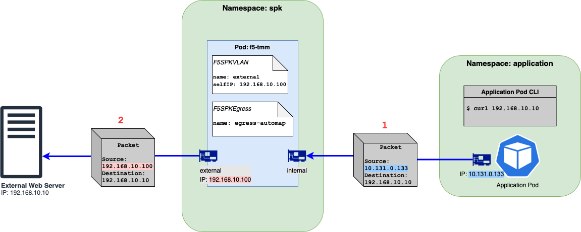
Figure 1: Egress traffic flow from client to external server using SNAT Automap.
Note
The Figure 1 diagram does have an F5SPKVLAN CR config for the internal f5-tmm interface but it is omitted from the diagram.
The diagram shows a packet’s source and destination IP addresses when an outgoing request is made. In the example above, the Application Pod issues a curl to the external web server.
The packet going out of the Application Pod will show a destination of 192.168.10.10 and a source IP address of 10.131.0.133, the IP of the Application Pod. This packet will get routed to f5-tmm.
Now that egress is enabled, f5-tmm will send this packet out the external network interface AND will do a SNAT using a source IP of 192.168.10.100, the IP address of the external IP address.
Enable Egress Traffic Using SNAT Pool
Another SNAT option when enabling egress is using SNAT Pool. The main advantage of using this option is to provide scalability for your use case. When using the SNAT Automap option, the number of active connections are limited by the number of ephemeral ports handled by the worker node’s OS. If you are expecting to see more active connections than that, then using a SNAT Pool is the next best option. The SNATPool CR, which will be created here, is used to define multiple IPs for f5-tmm to SNAT. So when egress traffic from an application pod is proxied through f5-tmm, instead doing SNAT using an IP from a F5SPKVLan CR, it will pick an IP address from the list of IPs on the IngressRouteSnatpool CR. The IPs an administrator would use are typically IP ranges from the same subnet. We will be going through a couple cases when using SNAT Pools.
Using SNAT Pool with IPs from the same subnet
Using SNAT Pool with IPs from different subnets
SNAT Pool Using IPs From Single Subnet
Take the following steps to create a SNAT Pool with IPs from one subnet.
Assumptions
Single f5-tmm deployment (no horizontal scaling)
External interface on 1.2
External subnet: 192.168.10.0/24
Create a IngressRouteSnatpool CR by applying the example yaml file below. This file is using 2 IPs which belong in the same subnet as 192.168.10.0/24.
apiVersion: "k8s.f5net.com/v1"
kind: IngressRouteSnatpool
metadata:
  name: egress-snatpool-cr
  namespace: <spkNamespace>
spec:
  name: sp1
  addressList:
    - - 192.168.10.200
      - 192.168.10.201
Note
This CR must be created in the same namespace where the SPK Controller is installed.
Create the F5SPKEgress CR where
spec.egressSnatpoolis the name of the SNAT Pool name specified fromspec.nameon the newly create IngressRouteSnatpool CR from step one right above.apiVersion: "k8s.f5net.com/v1" kind: F5SPKEgress metadata: name: egress-snat-pool namespace: <spkNamespace> spec: egressSnatpool: sp1
Note
Like the F5SPKEgress CR using the SNAT Automap option, this CR must be created in the same namespace where the SPK Controller is installed.
Take a look at a diagram below illustrating this config. The SNAT address on packets going outside the cluster will be an IP specified from the SNAT Pool CR.
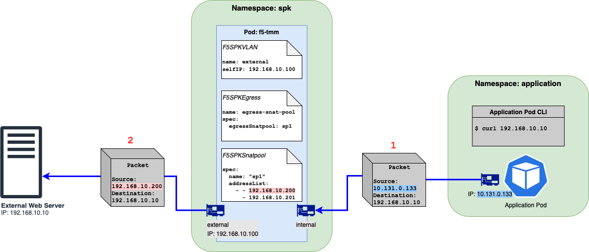
Figure 2: Egress traffic flow from client to external server using SNAT Pool.
Note
The Figure 2 diagram does have an F5SPKVLAN CR config for the internal f5-tmm interface but it is omitted from the diagram.
The diagram shows a packet’s source and destination IP addresses when an outgoing request is made. In the example above, the Application Pod issues a curl to the external web server.
Like the SNAT Automap option, the packet going out of the Application Pod will show a destination of 192.168.10.10 and a source IP address of 10.131.0.133, the IP of the Application Pod.
Now that egress is enabled, f5-tmm will send this packet out the external network interface AND will do a SNAT using the source IP of 192.168.10.200, one of the IP addresses from the IngressRouteSnatpool CR.
SnatPool Using IPs From Multiple Subnets
It is possible to use a list of IPs where each of them can be from different subnets. This section here will go through the configuration needed to make this happen.
Assumptions
Single f5-tmm deployment (no horizontal scaling)
External interface on 1.2
External subnets are:
192.168.10.0/24
192.168.20.0/24
Important
You can only specify one Self-IP per F5SPKVLAN CR per f5-tmm pod.
If your environment have external servers that are on different subnets and you want your egress traffic to proxy through a single SPK deployment, the F5SPKVlan CRs must be configured such that the spec.tag must be different for each subnet. So, subnet A needs to use vlan tag X and subnet B must use vlan tag Y. You cannot use subnet A and B on vlan tag X. An example using real IPs and VLAN values:
A F5SPKVlan CR configured with Self IP 192.168.10.100/24 on vlan tag 100.
A F5SPKVlan CR configured with Self IP 192.168.20.100/24 on vlan tag 101.
You cannot configure an F5SPKVlan CR with Self IPs 192.168.10.100/24 and 192.168.20.100/24 on vlan tag 100.
Take the steps below to configure your SNAT Pool to use a list of IPs from multiple subnets.
Verify your VLAN and Self-IPs are properly configured on the external side. You should have one entry per subnet. An example of valid F5SPKVlan CRs is shown below.
apiVersion: "k8s.f5net.com/v1"
kind: F5SPKVlan
metadata:
  name: "vlan-external-1"
spec:
  tag: 100
  name: external-1
  interfaces:
    - "1.2"
  selfip_v4s:
    - 192.168.10.100
  prefixlen_v4: 24
---
apiVersion: "k8s.f5net.com/v1"
kind: F5SPKVlan
metadata:
  name: "vlan-external-2"
spec:
  tag: 101
  name: external-2
  interfaces:
    - "1.2"
  selfip_v4s:
    - 192.168.20.100
  prefixlen_v4: 24
Create your IngressRouteSnatpool CR so your list have IPs from different subnets.
apiVersion: "k8s.f5net.com/v1"
kind: IngressRouteSnatpool
metadata:
  name: egress-snatpool-cr
  namespace: <spkNamespace>
spec:
  name: sp1
  addressList:
    - - 192.168.10.200
      - 192.168.10.201
      - 192.168.20.200
      - 192.168.20.201
Note
This CR must be created in the same namespace where f5ingress is installed.
Create the F5SPKEgress CR where
spec.egressSnatpoolis the name of the SNAT Pool name specified fromspec.nameon the IngressRouteSnatpool CR from the step right above.apiVersion: "k8s.f5net.com/v1" kind: F5SPKEgress metadata: name: egress-snat-pool namespace: <spkNamespace> spec: egressSnatpool: sp1
Note
Like the F5SPKEgress CR using the SNAT Automap option, this CR must be created in the same namespace where the SPK Controller is installed.
Take a look at a diagram below illustrating the config with multiple external subnets. The SNAT address on packets going outside the cluster will be an IP specified from the IngressRouteSnatpool CR by matching the subnet of the desination with that of external Vlan.
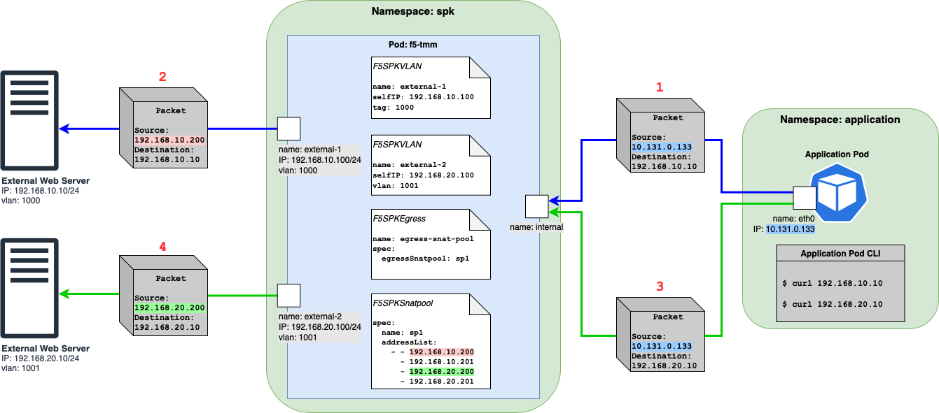
Figure 3: Egress traffic flow from client to external servers with multiple subnets using SNAT Pool.
When the application pod initiates a connection to external server 1 (192.168.10.10) via
curl, the source IP of traffic will be the IP of the application pod (10.131.0.133). You can refer to packet 1 & 2. The f5-tmm pod will then pick an IP from the SNAT pool and then use it for traffic going to the external webserver. Here the SNAT IPs that match the destination (192.168.10.10) subnet are 192.168.10.200 as well as 192.168.10.201 and it can use either. In this case, it picks 192.168.10.200 highlighted in red.When the application pod initiates a connection to external server 2 (192.168.20.10) via
curlthe source IP of traffic will be the IP of the application pod (10.131.0.133). You can refer to packet 3 & 4. Packet 3 has the same source IP as packet 1 but has a different destination. The f5-tmm pod will then pick an IP from the SNAT pool then use it for traffic going to the second external webserver on a different subnet. Here the SNAT IPs that match the destination (192.168.20.10) subnet are 192.168.20.200 as well as 192.168.20.201 and it can use either. In this case, it picks 192.168.20.200 highlighted in green.
Note
The SNAT address is picked based on the subnet matching the nexthop. In above examples the nexthop is the destination IP and so we match the subnet of the destination IP with those of the SNAT IPs. When the network configuration contains static routes, the nexthop is the gateway IP rather than the destination IP, and the matching of subnets occurs between the gateway IP and the SNAT IPs
Note
Here is what happens during a match: If there is an exact match we round robin amongst the matching SNAT IPs, else we pick any arbitrary SNAT IP
Traffic to destination 192.168.10.xx will always pick one of the SNAT IPs matching the subnet (192.168.10.200 and 192.168.10.201) and iterate amongst them using the round-robin algorithm and never pick 192.168.20.200 or 192.168.20.201.
Similarly, traffic to destination 192.168.20.xx will always pick one of the SNAT IPs matching the subnet (192.168.20.200 and 192.168.20.201) and iterate amongst them using the round-robin algorithm and never pick 192.168.10.200 or 192.168.10.201.
If traffic to a destination subnet does not match the subnet of any SNAT IPs in the SNAT Pool (for example, outbound traffic going to external server 3 with IP, say, 192.167.10.10 and in the presence of an additional F5SPKVlan CR named vlan-external-3 configured with Self-IP 192.167.10.100/24), f5-tmm will arbitrarily pick any of the SNAT IPs in the SNAT Pool (192.168.10.200, 192.168.10.201, 192.168.20.200, 192.168.20.201) and no round robin algorithm will be used amongst the SNAT IPs.
Troubleshooting
Configuration Errors
Any CRs created from the F5 CRDs are configuration changes to the f5-tmm pod. Configuration errors are normally found in the f5ingress pod.
Below is an example when I try to create a second Self IP on the same interface.
$ oc logs f5ingress-f5ingress-57b9b467cc-bj555 -c f5ingress-f5ingress
. . .
E1216 00:00:11.875676       1 controller_vlan.go:609] Error with  AddOrUpdateF5Vlan configuration for spk/grpc-svc: Error adding or updating F5Vlan spk/vlan-external-3: Duplicate tag 1203 for vlan 'spk-vlan-external-3', this tag is already used by vlan 'spk-vlan-external-4' 1203
Verifying Configurations
You can verify the CRs created are shown in the f5ingress-f5ingress container from the f5ingress pod as well. You will see a line with Send GRPC Message that corresponds to a GrPC message.
Below is a snippet where a F5SPKEgress CR is actually applied to the f5-tmm pod when looking at the logs from f5ingress-f5ingress.
$ oc logs f5ingress-f5ingress-57b9b467cc-bj555 -c f5ingress-f5ingress
. . .
I1206 23:47:36.314554       1 grpccfg2.go:443] gRPC - Send GRPC Message:
        {
                "embedded": {
                "@type": "declTmm.transaction_start",
                "transaction_number": 0
                }
        }
{
"embedded": {
  "@type": "declTmm.delete_msg",
  "revision": 1,
  "uuid": [

"egress-ipv4-address-list",
"egress-ipv4-port-list",
"egress-ipv4-tmc",
"egress-ipv4",
"egress-ipv4-virtual-server-profile",
"egress-dns-ipv4-port-list",
"egress-dns-pool-member-list",
"egress-dns-pool",
"egress-dns-ipv4-tmc",
"egress-dns-ipv4",
"egress-dns-tcp-ipv4-tmc",
"egress-dns-tcp-ipv4",
"egress-dns-ipv4-dns-profile",
"egress-dns-ipv4-udp-profile",
"egress-dns-ipv4-tcp-profile",
"egress-dns-ipv4-dns-virtual-server-profile",
"egress-dns-ipv4-dns-tcp-virtual-server-profile",
"egress-dns-ipv4-udp-virtual-server-profile",
"egress-dns-ipv4-tcp-virtual-server-profile",
"egress-ipv4-nat46-address-list",
"egress-ipv4-nat46-tmc",
"egress-ipv4-nat46",
"egress-ipv4-nat46-virtual-server-profile"
  ]
}
If you are expecting to see a CR applied to f5-tmm you would need to look at the f5ingress-f5ingress logs. Below is a snippet when the cwc service is not fully configured. Below is an example if you do not have licensing fully configured and is preventing certain CRs from being applied.
$ oc logs f5ingress-f5ingress-57b9b467cc-bj555 -c f5ingress-f5ingress
. . .
I1203 05:19:13.780862       1 manager.go:212] Configs are not allowed since license is not activated