Networking Overview
Overview
To support the high-performance networking demands of communication service providers (CoSPs), Service Proxy for Kubernetes (SPK) requires three primary networking components: SR-IOV, OVN-Kubernetes, and BGP. The sections below offer a high-level overview of each component, helping to visualize how they integrate together in the container platform:
SR-IOV VFs
SR-IOV uses Physical Functions (PFs) to segment compliant PCIe devices into multiple Virtual Functions (VFs). VFs are then injected into containers during deployment, enabling direct access to network interfaces. SR-IOV VFs are first defined in the OpenShift networking configuration, and then referenced using SPK Helm overrides. The sections below offer a bit more detail on these configuration objects:
OpenShift configuration
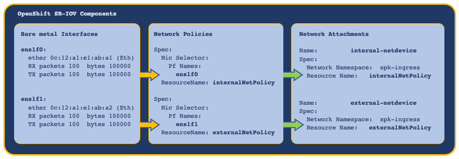
The OpenShift network node policies and network attachment definitions must be defined and installed first, providing SR-IOV virtual functions (VFs) to the cluster nodes and Pods.
In this example, bare metal interfaces are referenced in the network node policies, and the network attachment definitions reference node policies by Resource Name:
SPK configuration
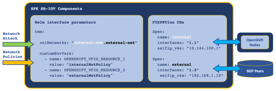
The SPK Controller installation requires the following Helm tmm parameters to reference the OpenShift network node policies and network node attachments:
cniNetworks- References SR-IOV network node attachments, and orders the f5-tmm container interface list.OPENSHIFT_VFIO_RESOURCE- References SR-IOV network node policies, and must be in the same order as the network node attachments.
Once the Controller is installed, TMM’s external and internal interfaces are configured using the F5SPKVlan Custom Resource (CR).
In this example, the SR-IOV VFs are referenced and ordered using Helm values, and configured as interfaces using the F5SPKVlan CR:
OVN-Kubernetes
The OpenShift Cluster Network Operator must use the OVN-Kubernetes CNI as the defaultNetwork, to enable features relevant to SPK such as egress-gw.
 Note: OVN-Kubernetes is referred to as iCNI2.0 or Intelligent CNI 2.0, and is based on Open vSwitch.
The OVN-Kubernetes egress-gw feature enables internal Pods within a specific Project to use Service Proxy TMM’s internal SR-IOV (physical) interface, rather than the default (virtual) network as their egress default gateway.
Annotations
OVN-Kubernetes annotations are applied to Pods in the Project, and are used by the OVN database (DB) to route packets to TMM. Using OVN, IP address allocation and routing behave as follows:
- Each worker node is assigned an IP address subnet by the network operator.
- Pods scheduled on a worker node receive IP addresses from the worker subnet.
- Pods are configured to use their worker node as the default gateway.
- Egress packets sent by Pods to the worker node are routed using the OVN DB, not the kernel routing table.
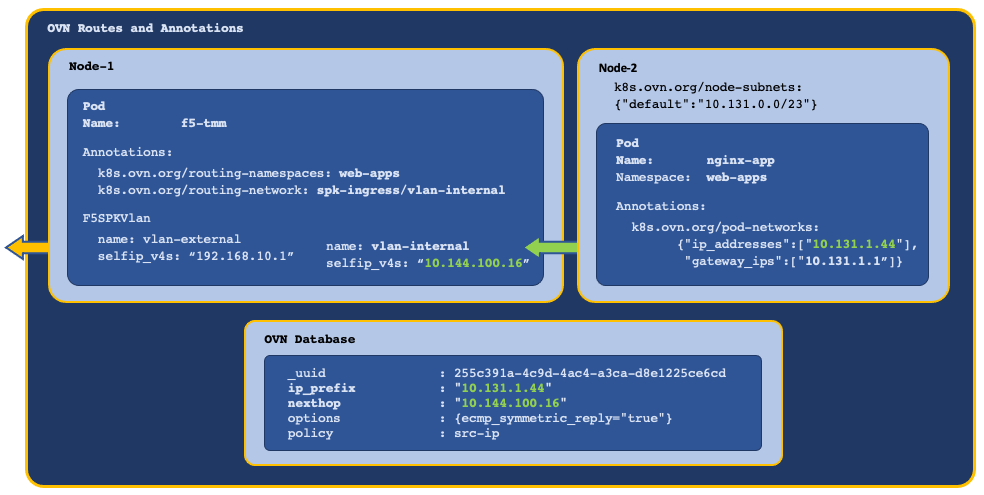
OVN annotations are applied to the Service Proxy TMM Pod using the parameters below:
- k8s.ovn.org/routing-namespaces - Sets the Project for Pod egress traffic using the Controller
watchNamespaceHelm parameter. - k8s.ovn.org/routing-network - Sets the Pod egress gateway using the F5SPKVLan
spec.internalCustom Resource (CR) parameter.
In this example, OVN creates mapping entries in the OVN DB, routing egress traffic to TMM’s internal VLAN self IP address:
Viewing OVN routes
Once the application (Pods) are installed in the Project, use the steps below to verify the OVN DB routes are pointing to Service Proxy TMM’s internal interface.
Note: The OVN-Kubernetes deployment is in the openshift-ovn-kubernetes Project.
 Important: It’s important to note that SPK v1.9.1 supports OpenShift v4.14 and utilizes the ovnkube-node daemon set.
Log in to the OVN DB:
oc exec -it ds/ovnkube-node -n openshift-ovn-kubernetes -- bash
View the OVN routing table entries using TMM’s VLAN self IP address as a filter:
ovn-nbctl --no-leader-only find Logical_Router_Static_Route nexthop=<tmm self IP>
In this example, TMM’s self IP address is 10.144.100.16:
ovn-nbctl --no-leader-only find Logical_Router_Static_Route nexthop=10.144.100.16
In this example, routing entries exist for Pods with IP addresses 10.131.1.100 and 10.131.1.102, pointing to TMM self IP address 10.144.100.16:
_uuid               : 61b6f74d-2319-4e61-908c-0f27c927c450
ip_prefix           : "10.131.1.100"
nexthop             : "10.144.100.16"
options             : {ecmp_symmetric_reply="true"}
policy              : src-ip

_uuid               : 04c121ff-34ca-4a54-ab08-c94b7d62ff1b
ip_prefix           : "10.131.1.102"
nexthop             : "10.144.100.16"
options             : {ecmp_symmetric_reply="true"}
policy              : src-ip
The OVN DB example confirms the routing configuration is pointing to TMM’s VLAN self IP address. If this entry does not exist, OVN annotations are not being applied and further OVN-Kubernetes troubleshooting should be performed.
OVN ECMP
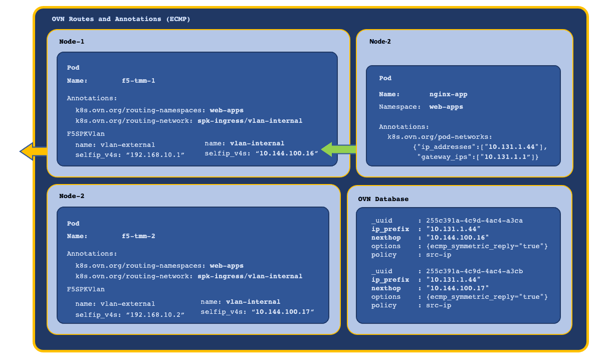
When TMM is scaled beyond a single instance in the Project, each TMM Pod receives a self IP address from the F5SPKVlan IP address list. Also, OVN-Kubernetes creates a routing entry in the DB for each of the Service Proxy TMM Pods and routes as follows:
- OVN applies round robin load balancing across the TMM Pods for each new egress connection.
- Connection tracking ensures traffic arriving on an ECMP route path returns via the same path.
- Scaling TMM adds or deletes OVN DB routing entries for each Running TMM replica.
In this example, new connections are load balanced and connection tracked:
BGP
The SPK CRs that support application traffic, configure Service Proxy TMM with a virtual server IP address and load balancing pool. In order for external networks to learn TMM’s virtual server IP addresses, Service Proxy must deploy with the f5-tmm-routing container, and a Border Gateway Protocol (BGP) session must be established.
Important: The Kubernetes Service object referenced by the SPK CR must have at least one Endpoint for the virtual server IP to be created and advertised.
In this example, the tmm-routing container advertises TMM’s virtual IP address to an external BGP peer:
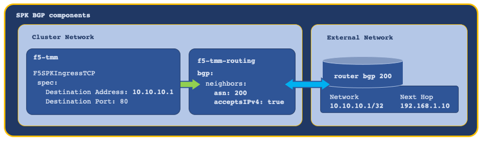
For assistance configuring BGP, refer to the BGP Overview.
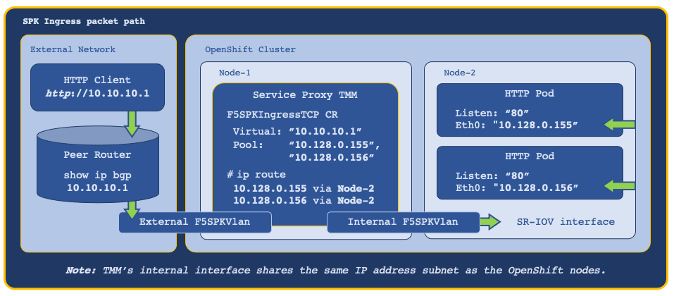
Ingress packet path
With each of the networking components configured, and one of the SPK CRs installed, ingress packets traverse the network as follows:
Feedback
Provide feedback to improve this document by emailing spkdocs@f5.com.