Secure SPK Deployment On Secondary Interfaces Using Macvlan
Overview
Service Proxy for Kubernetes (SPK) can apply security functions using Firewall CRDs to ingress and egress traffic on your application. This only applies to traffic on the default interface, eth0, of your applications. But you might need to also apply security functions to an additional interface on your application. This guide walks you through enabling SPK firewall on the secondary network interface.
 Note: The SPK v1.9.0 Multus Capture is considered Early Access (EA). EA features are unsupported and are made available to get customer feedback on feature functionality and stability.
The firewall CRDs can be found in the SPK Firewall CRDs: Secure SPK section of the SPK CRs page
Requirements
Ensure you have:
- Installed the SPK Cert Manager
- Installed the SPK Software
- Installed the SPK CWC
- Installed the RabbitMQ Pod
- Installed Licensed SPK
- Installed SPK Controller
- Deployed your application in SPK watch namespace
- TCP App used as example in this guide
- A secondary interface using macvlan
- Configured SPK network specific configurations, such as F5SPKVlan
- Access to K8S Cluster with SPK
High Level Network Overview
When you add an additional network interface on a pod using the Multus CNI, traffic going to and from that interface bypasses the default CNI. And for us, it also bypasses SPK. An example illustrating this is shown below.
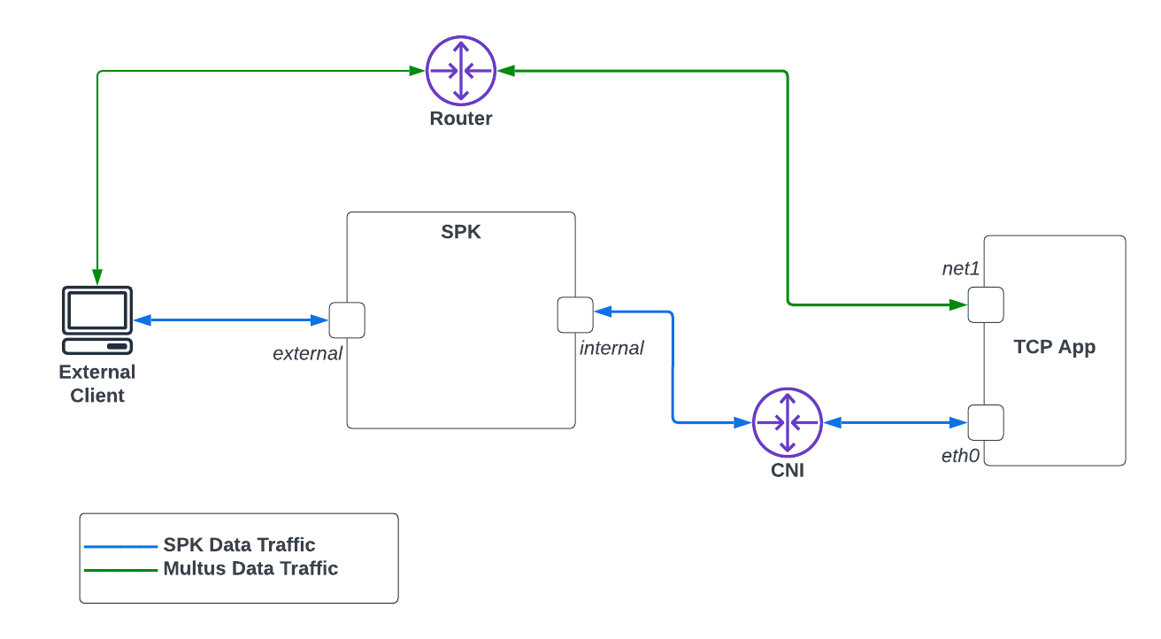 Diagram 1: Traffic on Additional Pod Interfaces
In Diagram 1, traffic from a pod, by default, uses the default CNI for network traffic. In the example here, the default network traffic is through eth0. But when you add an additional interface, say net1, traffic will bypass the default CNI and thus SPK. And in the case here, it is connected to a router. Because of the different network route, you will not be able to apply any SPK security features on net1 by default.
This guide will walk through steps to change network traffic on the secondary interface so that it goes though SPK enabling firewall functions.
This release will route traffic from only ONE additional interface on your application through SPK.
We will assume the following SPK configuration and the overall infrastructure. The network IP address examples throughout this guide will be also be based from the diagram below.
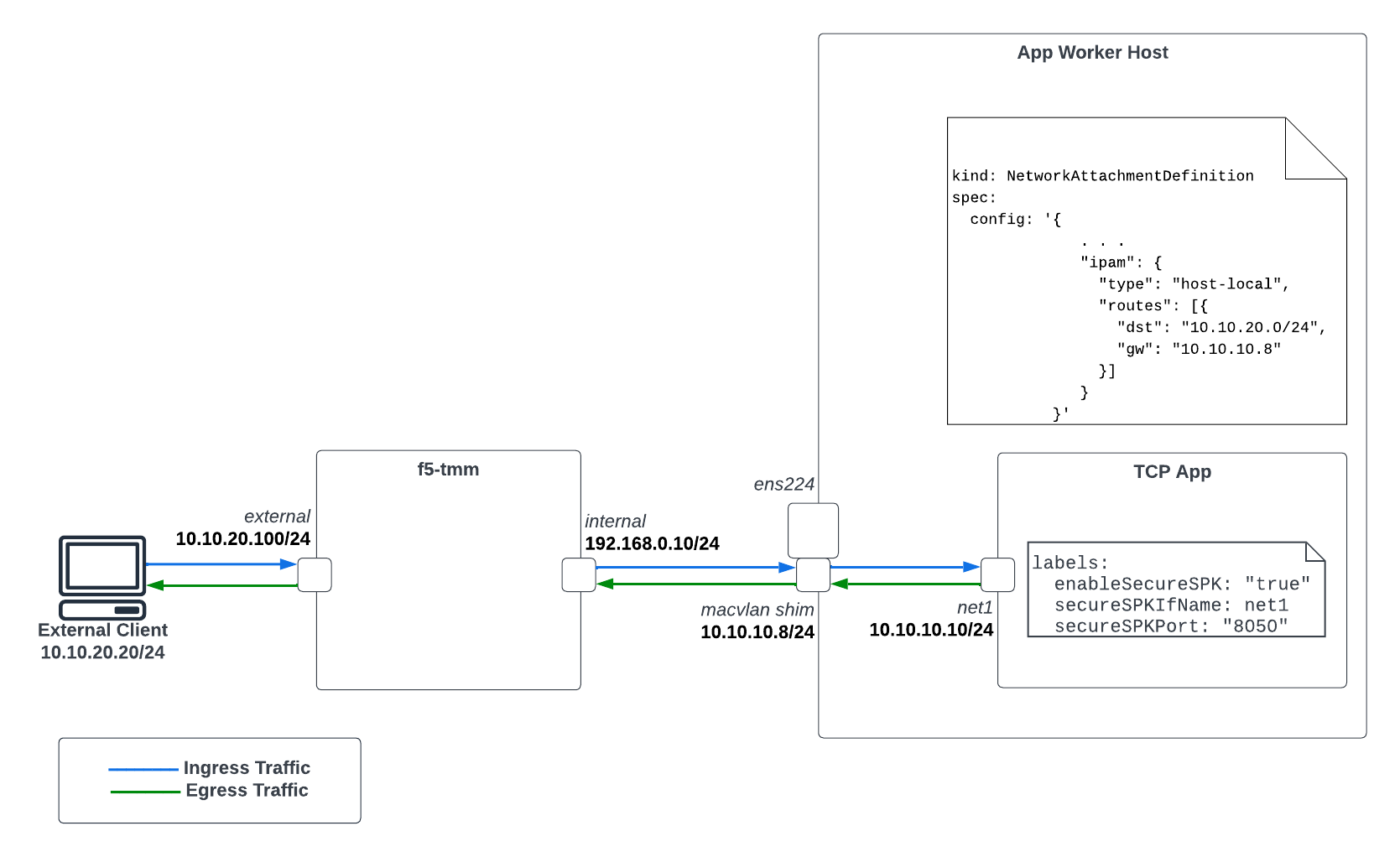 Diagram 2: SPK Firewall Infrastructure Overview Using Multus
The External Client has a static route configured such that 10.10.10.0/24 is routed to the external interface of SPK. A snippet showing this route below.
external-client $ ip route
10.10.10.0/24 via 10.10.20.100 dev ens224 proto static
. . .
Secure SPK for Applications Using Secondary Interface
Before You Begin
- You will need admin access to the worker nodes where your application pods are deployed.
- Confirm the CSRC container image, spk-csrc, is uploaded to your image registry. Refer to the Upload the image section of the SPK Software for more information.
Environment Setup
In order to enable the additional interface on your application so traffic is routed through SPK, use the instructions below to setup the networking requirements.
(OpenShift) Enable Route Via Host
OpenShift’s CNI, OVN-Kubernetes, needs to enable routingViaHost. Below is a snippet of networks.operator.openshift.io that shows how to enable this feature.
Run
oc edit networks.operator.openshift.ioto confirm it is enabled.apiVersion: operator.openshift.io/v1 kind: Network spec: defaultNetwork: ovnKubernetesConfig: gatewayConfig: routingViaHost: true
Create Additional Macvlan Shim Interface
The shim interface is an additional Macvlan bridge interface created on the worker nodes where your applications are deployed. This is required so your secondary Macvlan interface have connectivity SPK’s internal interface. Take the following steps to create this:
Establish SSH connection to the worker node where your application is deployed.
Determine the network interface that corresponds to SPK’s internal network. In this case here, it is br-ex.
Create the shim interface based from the interface used for SPK’s internal network.
ip link add spk-shim link br-ex type macvlan mode bridge
Assign an IP to the new spk-shim shim interface.
ip addr add 10.10.10.8/24 dev spk-shim
Bring up the shim interface
ip link set spk-shim up
Apply MacVlan Network attachment definition in Watch Namespace to assign an IP address to secondary interface of Application Pod (CNF)
10.10.20.0/24is the subnet configured on the external client.10.20.10.105is the configured IP address on the shim interface.
apiVersion: "k8s.cni.cncf.io/v1"
kind: NetworkAttachmentDefinition
metadata:
  name: macvlan-secondary
spec:
  config: '{
    "cniVersion": "0.3.1",
    "type": "macvlan",
    "mode": "bridge",
    "master": "ens224",
    "ipam": {
        "type": "host-local",
        "subnet": "10.20.10.0/24",
        "rangeStart": "10.20.10.170",
        "rangeEnd": "10.20.10.180"
      }
    }'
Deploy Calico Static Route Configuration (CSRC) Daemonset to Enable Egress
The CSRC Daemonset needs to be installed in order to enable egress traffic on the secondary interface of your application. This daemonset enables it by creating kernel rules and routes. Be sure to have the following settings configured on install.
| Setting | Value | Notes |
|---|---|---|
| daemonsetMode | secureSPK | |
| ipFamily | ipv4 | ipv4 or ipv6 |
| f5MiniCniInstall | no | |
| spec.interfacename | br-ex | select the host interface for data traffic |
| spec.json.ipPoolCidrInfo.cidrList | List | List of cluster CIDR |
| spec.json.ipPoolCidrInfo.ipPoolList | List | List of IPPool CIDR |
Generate the
values.yamlfile to be used for CSRC install. Below is used in this example.- Each cluster-cidrN list entry corresponds to each worker node’s network CIDR. You can find this by running
kubectl get node <nodeName> --output yamland looking atk8s.ovn.org/node-subnets. - The app-ip-pool corresponds to the entire cluster’s pod network.
daemonsetMode: secureSPK
ipFamily: ipv4
image:
  repository: <yourContainerImageRepo>
config:
  interfacename: br-ex
  json:
    ipPoolCidrInfo:
      cidrList:
        - name: cluster-cidr0
          value: 10.131.0.0/23
        - name: cluster-cidr1
          value: 10.128.2.0/23
      ipPoolList:
        - name: app-ip-pool
          value: 10.128.0.0/14
f5MiniCniInstall: no
- Each cluster-cidrN list entry corresponds to each worker node’s network CIDR. You can find this by running
Install CSRC
helm install mycsrc csrc-0.4.10.tgz -f values.yaml -n default
You should see as many pods as you have worker nodes. In the example below, my cluster has 2 worker nodes so there are a total of two pods where each is deployed to a worker node.
kubectl get pods -owide -n default
NAME                READY   STATUS    RESTARTS   AGE    IP           NODE                      NOMINATED NODE   READINESS GATES
f5-spk-csrc-4l6sc   1/1     Running   0          4d1h   10.75.77.9   ocp-worker2   <none>           <none>
f5-spk-csrc-hdwp4   1/1     Running   0          4d1h   10.75.77.8   -ocp-worker1   <none>           <none>
Enable SPK Firewall Functions on Application’s Secondary Interface
SPK firewall functions can be enabled on the secondary interface of your applications. It is done by adding the following labels to your applications that will result traffic from your secondary interface being routed to SPK. This can be enabled on a per application basis. Take the following steps to enable firewall functions on your secondary interface.
Enable Secure SPK
kubectl label pods <applicationPod> enableSecureSPK="true"
Provide the secondary interface name.
kubectl label pods <applicationPod> secureSPKCNFPodIfName=net1
Provide the port to secure.
kubectl label pods <applicationPod> secureSPKPort="8050"
You should now see the following labels when you describe your application.
kubectl describe pod <applicationPod>

. . .
Labels:           enableSecureSPK=true
                  secureSPKCNFPodIfName=net1
                  secureSPKPort=8050
                  . . .
Configure a Static Route on Application Pod (CNF) to reach to external destination from secondary interface
ip route add <external destinationIP>/<netmask> via <shim interface IP on CNF node> dev net1
For Example:
ip route add 10.7.1.201/32 via 10.20.10.101 dev net1
Validation
Application Worker Nodes
You can confirm the egress rules and routes from CSRC are configured properly by checking them on the worker node.
Establish SSH connection to your worker node where your application pod is running
List the ip rules
sh-4.4# ip rule list
32276:  from 10.10.10.10 lookup 276
. . .
List the route table that corresponds to the IP of the secondary interface
sh-4.4# ip route show table 276
default via 192.168.0.10 dev br-ex
192.168.0.10 via 192.168.0.10 dev br-ex
Validating Routes on TMM
You can confirm if TMM have a route to the secondary interface in the f5-tmm pod.
Go into the debug container from f5-tmm deployment
oc exec -it f5-tmm-56944774c-49shg -c debug -- bash
List routes
/ip r
10.10.10.10 via 192.168.0.10 dev internal
Validating Virtual Servers on TMM
Once you’ve added the enableSecureSPK=true, secureSPKCNFPodIfName, and secureSPKPort labels to the pod where you want
to enable traffic of secondary interface so that it routes to SPK, you should see the following
Virtual Servers created on the f5-tmm pod.
$ oc exec -it f5-tmm-56944774c-pdpql -c debug -- bash
/ tmctl -f /var/tmstat/blade/tmm0 virtual_server_stat -s name

name
-------------------------------------------------------
secure-egress-ipv4-virtual-server
secure-ingress-ipv4-virtual-server
Securing Traffic on Secondary Interface
You can now assign SPK Firewall functions to the secondary interface by defining firewall rules and policies. The global firewall rules you define will be applied to this traffic. Refer to the Secure SPK Deployment guide for additional details relating SPK Firewall.
Feedback
Provide feedback to improve this document by emailing spkdocs@f5.com.