F5 BIG-IP SSL Orchestrator Training Lab > All SSL Orchestrator Lab Guides > SSLO 201: Advanced Use Cases with SSL Orchestrator (Agility 2022 | 2 hours) > 3. Internal Layered SSL Orchestrator Architecture Source | Edit on
3.6. Create Secondary Topology
You will need to add an L3 Explicit topology for the outbound application server traffic. This topology will decrypt TLS and send traffic to a service chain consisting of:
New ICAP-based antivirus service
Existing Cisco Firepower TAP service
3.6.1. L3 Explicit Topology
Navigate to SSL Orchestrator > Configuration and Add a new topology.
Scroll to the bottom of the Configuration introduction page and click on the Next button.
Enter
appsvr_explicitas the topology name. Ensure that the name is entered exactly as shown because it will be referenced in a later step.Select the L3 Explicit Proxy topology type.
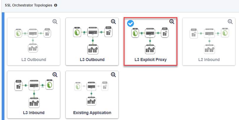
Click the Save & Next button to continue.
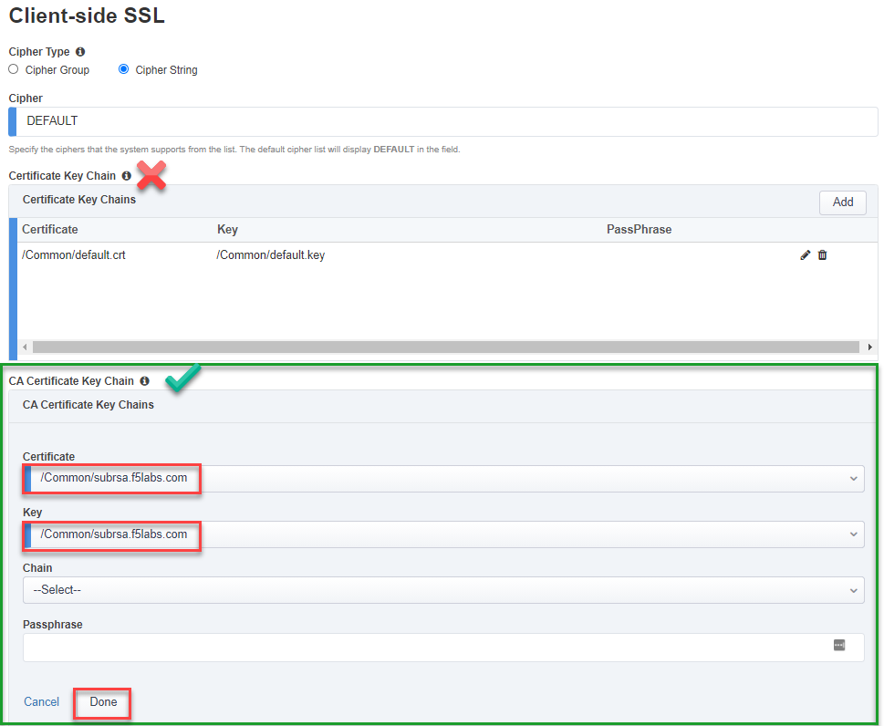
3.6.2. SSL Configurations
In the CA Certificate Key Chain section, click on the pencil icon to edit.
Select subrsa.f5labs.com for both Certificate and Key.
Warning
Ensure that you are editing the CA Certificate Key Chain shown above, not the Certificate Key Chain. They look very similar.
Click Done. The SSL settings have now been configured.
Click the Save & Next button to continue.
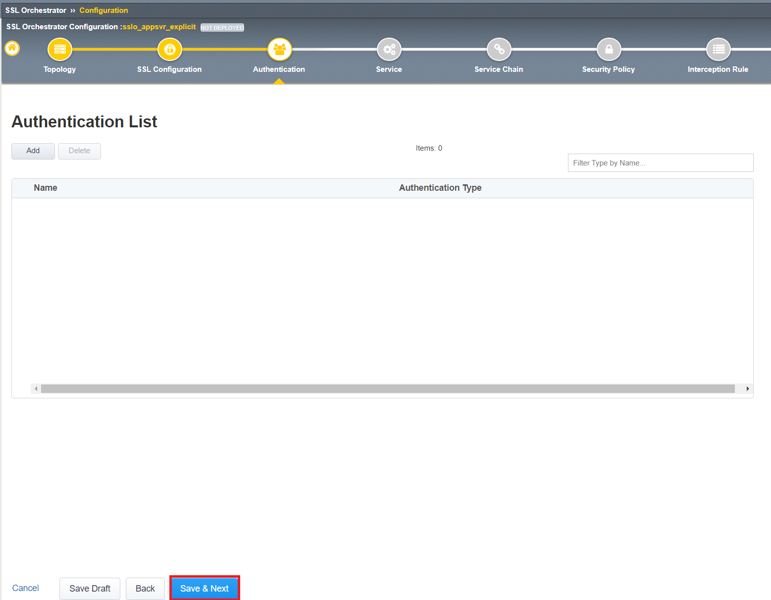
3.6.3. Authentication List
This section allows you to add Online Certificate Status Protocol (OCSP) Responders to validate the revocation status of a digital certificate. Since we are not using certificate-based authentication in this lab, we will skip this section and click Save & Next at the bottom of the page.
3.6.4. ICAP service
On the Services List screen, click the Add Service button.
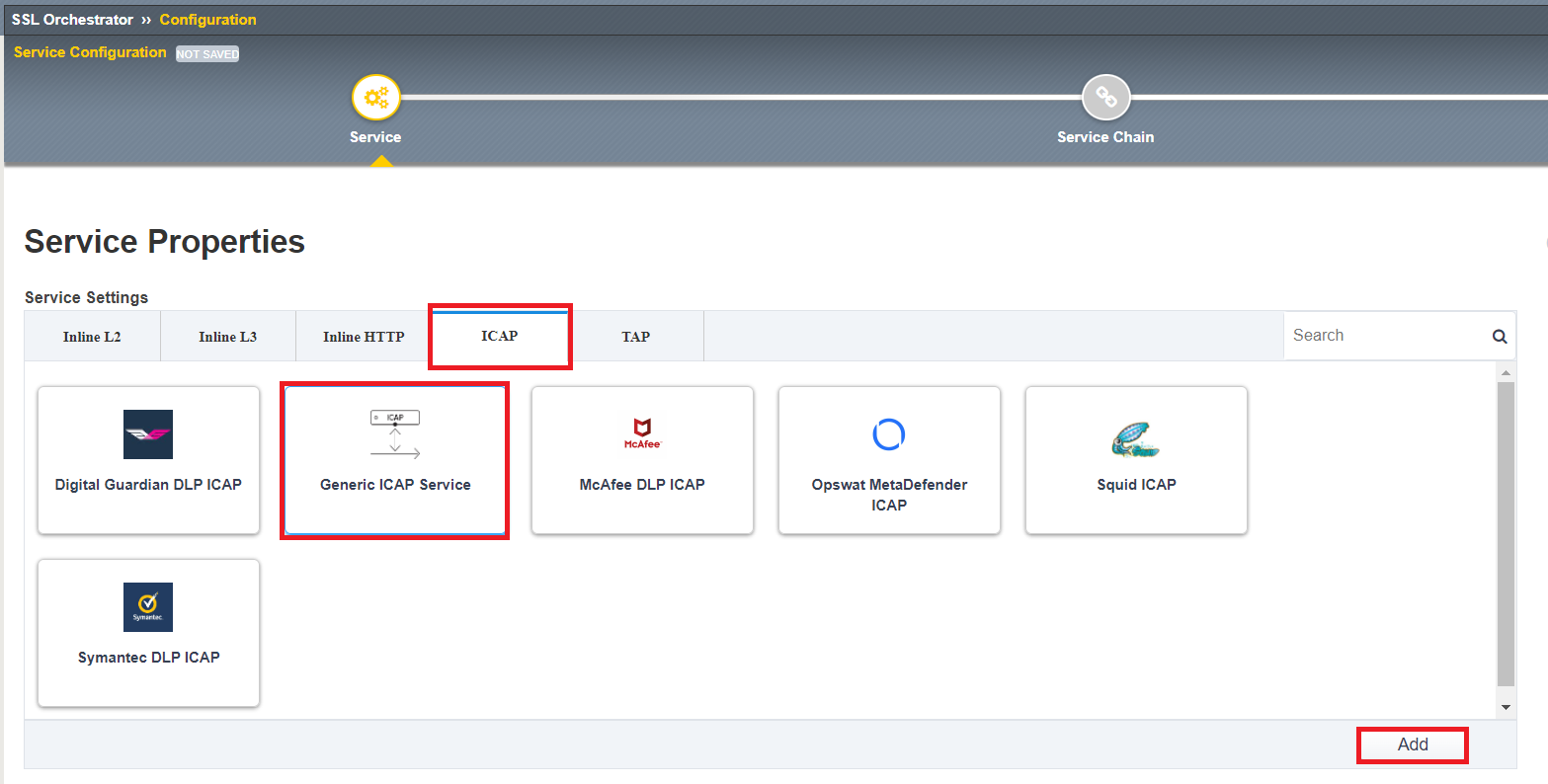
Click ICAP under the Service Settings heading
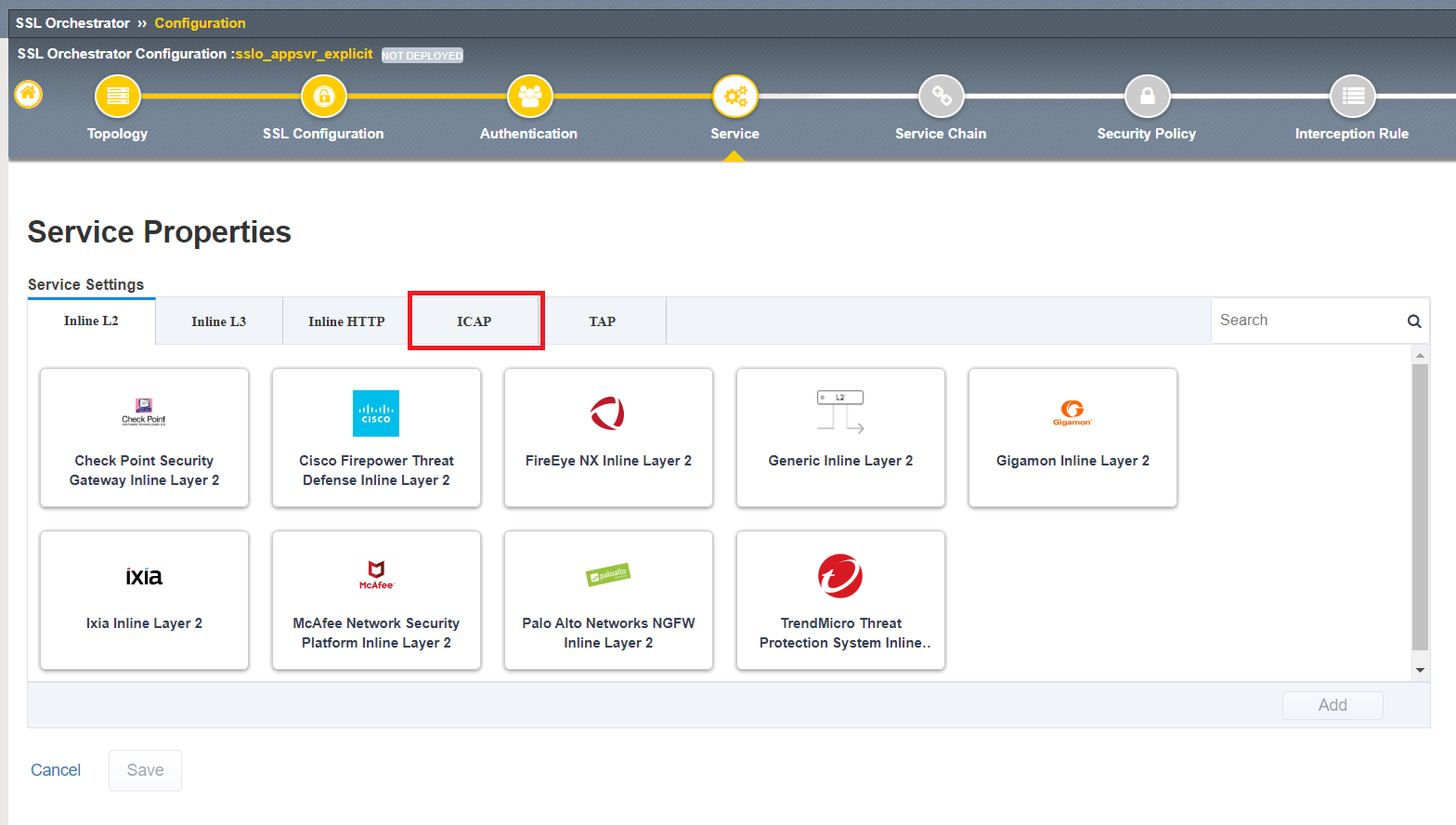
Select Generic ICAP Service and click the Add button
On the Service Properties screen, enter the following values:
Enter
CLAM_AVin the Name field.Enter
ClamAVin the Description field.In the ICAP Devices section, click on the Add button.
Enter
198.19.97.50in the IP Address field.Leave the Port set to
1344(default for ICAP).Click on Done to add the ICAP device.
Enter
/avscanin the Request Modification URI Path field.Enter
/avscanin the Response Modification URI Path field.Enter
1048576in the Preview Max Length(bytes) field.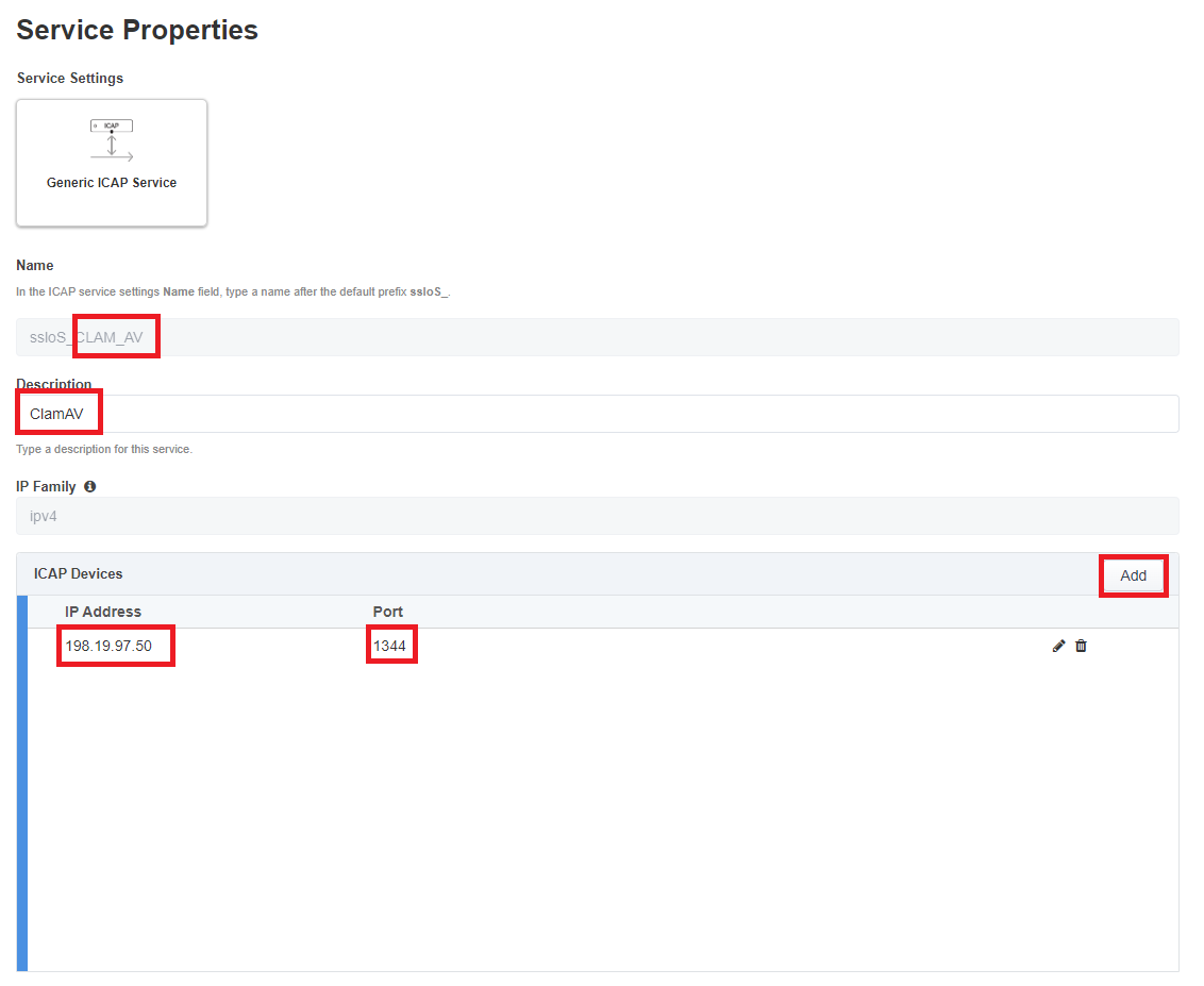
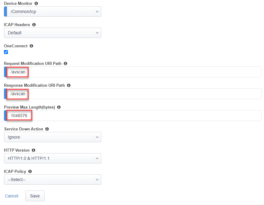
Click Save to return to the Services List.
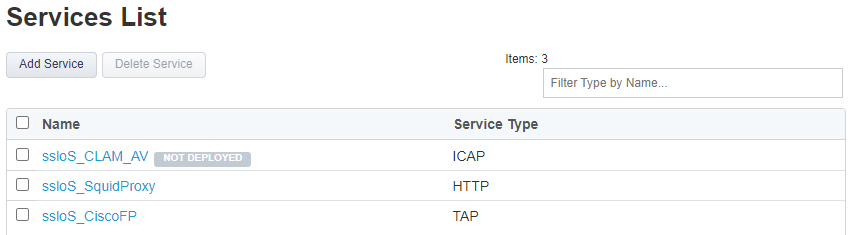
Click the Save & Next button to continue.
3.6.5. Service Chain
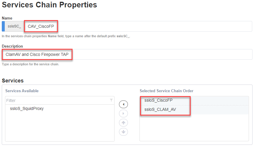
You now need to create a new Service Chain containing the CLAM_AV and Cisco Firepower TAP services.
On the Services Chain List screen, click the Add button.
On the Services Chain Properties screen, enter the following values:
Enter
CAV_CiscoFPin the Name field.Enter
ClamAV and Cisco Firepower TAPin the Description field.Services - select the CLAM_AV and CiscoFP services under Services Available and move them to Selected Service Chain Order
Click the Save button to return to the Service Chain List.
Click the Save & Next button to continue.
3.6.6. Security Policy
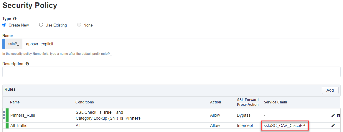
You now need to create a new Security Policy for the appsvr_explicit topology.
On the Security Policy screen, modify the All Traffic rule by clicking on the pencil icon.
Select the ssloSC_SC_CAV_CiscoFP Service Chain.
Click the OK button.
Click the Save & Next button to continue.
3.6.7. Interception Rule / Proxy Server Settings
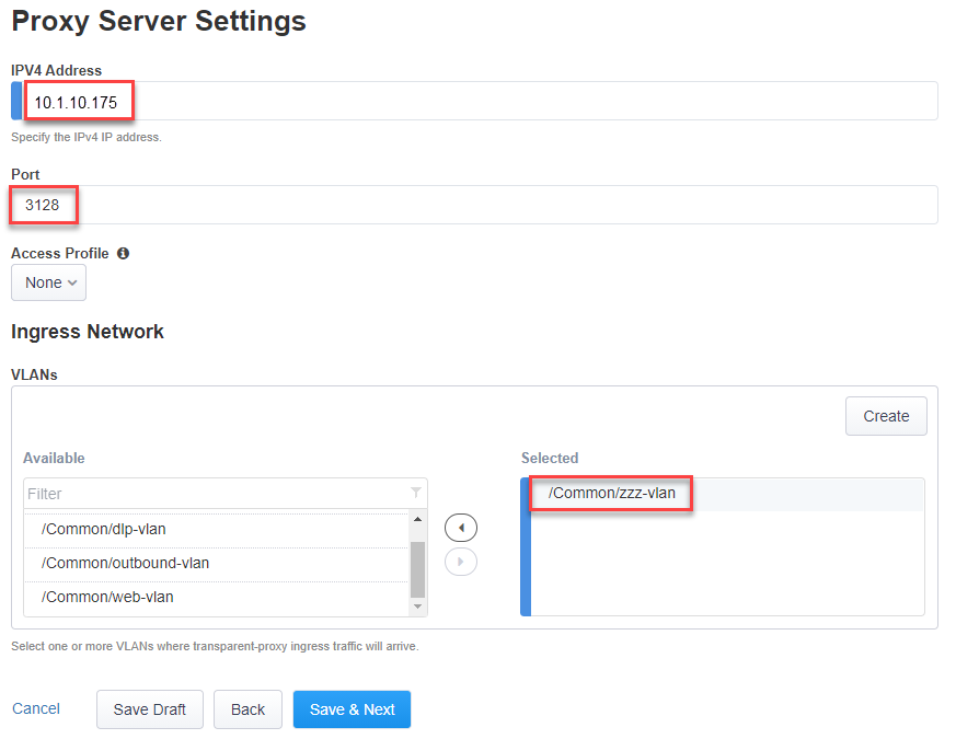
Skip down to the Proxy Server Settings section.
Enter
10.1.10.175in the IPV4 Address field.
Note
An IP address is required for an explicit proxy configuration, but it won't actually be referenced in this design since it is associated with an empty VLAN.
Leave the Port set to
3128(default value).In the VLANs section, select the /Common/zzz-vlan VLAN and and move it to Selected column.
Click the Save & Next button.
3.6.8. Egress Settings
On the Egress Settings screen, select Auto Map in the Manage SNAT Settings field.
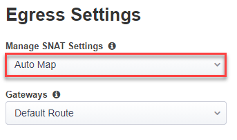
Click the Save & Next button.
3.6.9. Log Settings
On the Log Settings screen, leave all the default values.
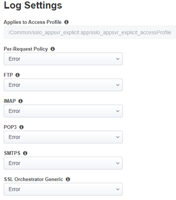
Click the Save & Next button to continue.
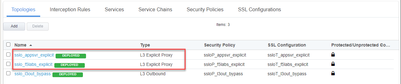
3.6.10. Summary
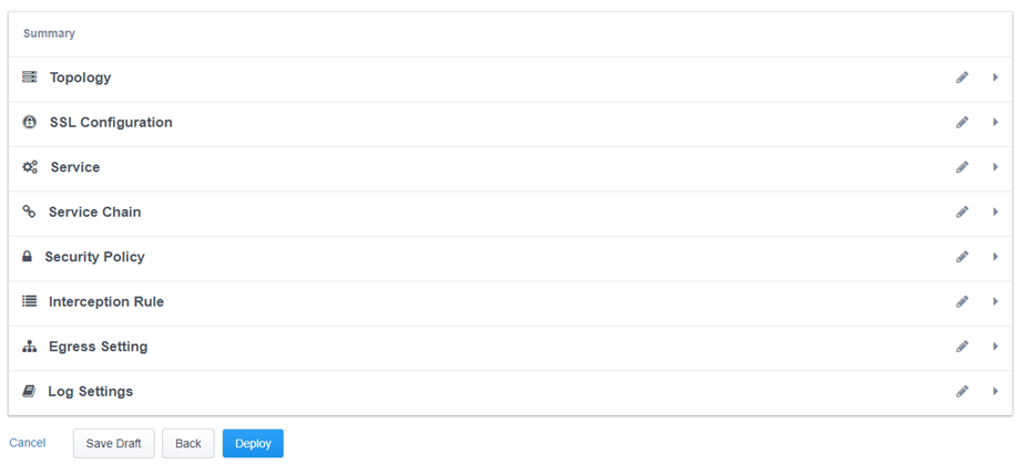
Click the Deploy button.
When successfully deployed, click the OK button to return to the SSL Orchestrator Configuration screen.
You should now have two L3 Explicit topologies. The third topology is an L3 Outbound (transparent) topology that is not applicable to this lab exercise.