2.5. Creating a Reverse Proxy Topology
2.5.1. What it is
A topology is an entry point for network traffic into SSL Orchestrator. A reverse proxy topology is created to enable layer 3 (routed) “inbound” traffic to flow into SSL Orchestrator for decryption and service chain processing. Inbound traffic flow is normally associated with external clients (i.e. clients on the Internet) attempting to access internal resources. In SSL Orchestrator, a reverse proxy also defines the F5 BIG-IP as the owner of the target resource’s encryption keys.
The reverse proxy topology generally describes two slightly different use cases for inbound traffic.
Gateway mode - where SSL Orchestrator sits in front of a separate application delivery controller (ex. F5 BIG-IP LTM, or another load balancer) or a routed path. The primary attributes of the gateway mode are a wildcard (0.0.0.0/0) listener to grab traffic destined to all IP addresses, no pool assignment, and no destination address translation (no NAT). Destination addresses from the external client therefore point to locations behind SSL Orchestrator.
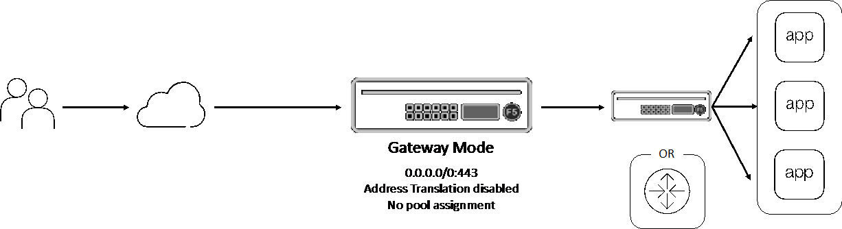
Figure 19: Reverse proxy topology gateway mode
Application” mode - where the client targets an address and port on the F5 BIG-IP itself. The primary attributes of the application mode are an IP address and port-specific listener, backend pool assignment, and enabled destination address translation (NAT). An SSL Orchestrator reverse proxy topology in application mode behaves very much like a traditional F5 BIG-IP reverse proxy virtual server, except that SSL Orchestrator manages the complete configuration workflow, including mandatory re-encryption to the backend server.

Figure 20: Reverse proxy topology application mode
2.5.2. How to build it
The following steps illustrate how to build a simple reverse proxy topology. As there are two modes that a reverse proxy topology can be deployed with (gateway and application), both are explored here.
Topology Properties |
User Input |
|---|---|
The Topology Properties page provides 5 selections: |
|
Topology name |
Enter a unique name here. |
Description |
Optionally enter a description here. |
Protocol |
Select between TCP, UDP, Other (non-TCP/non-UDP), and Any (combination of TCP, UDP and non-TCP/non-UDP). |
IP Family |
Select between IPv4 and IPv6. |
SSL Orchestrator Topologies |
Select the L3 Inbound topology here. |
Mode |
Present in 9.1 and above, the Mode setting defines the topology as an application or gateway mode configuration. |
Note
SSL and TLS are used primarily with TCP-based protocols topologies. The TCP protocol selection creates the necessary architecture to perform decryption and re-encryption. UDP traffic is not decrypted but can be service chained. Other (non-TCP/non-UDP) is not decrypted and not service chained. This topology selection creates a routed outbound path for non-TCP/non-UDP traffic.
Click Save & Next to proceed.
SSL Configurations |
User Input |
|---|---|
The SSL Configurations page manages all decryption and re-encryption controls for this topology. |
|
Client-side SSL |
|
Cipher Type |
Unless a more complex configuration is required, a Cipher String is typically most appropriate here. |
Cipher |
With the above Cipher String selection, enter a cipher string value here. DEFAULT is the baseline recommended practice cipher string as provided and maintained by F5 BIG-IP. |
Certificate Key Chain |
Edit and select an end-entity server certificate and private key here. Click Done to proceed. |
Server-side SSL |
|
Cipher Type |
Unless a more complex configuration is required, a Cipher String is typically most appropriate here. |
Cipher |
With the above Cipher String selection, enter a cipher string value here. DEFAULT is the baseline recommended practice cipher string as provided and maintained by F5 BIG-IP. |
Trusted Certificate Authorities |
This option presents a selection of CA bundle files to be used to validate server certificates. As this is an inbound topology, the server is also typically an internal resource, thus may not possess a publicly-issues certificate. Setting the next two settings to ignore prevents improper validation from breaking the connection. |
Expire Certificate Response |
This setting controls what happens when a server certificate is expired, and the options are Drop (drop the connection) or Ignore (ignore validation and continue). For inbound topologies it is usually appropriate to set this to Ignore. |
Untrusted Certificate Response |
This setting controls what happens when a server certificate is untrusted, per the supplied Trusted Certificate Authorities bundle file, and the options are Drop (drop the connection) or Ignore (ignore validation and continue). For inbound topologies it is usually appropriate to set this to Ignore. |
Click Save & Next to proceed.
Services List |
User Input |
|---|---|
For simplicity of this initial topology configuration, security services are defined in the Services chapter of this deployment guide. Please navigate to this chapter for complete information on configuration of services within SSL Orchestrator. |
|
Click Save & Next to proceed.
Service Chain List |
User Input |
|---|---|
If Services have been created per the previous step, create service chains to contain the services for use by security service policies. Click the Add button. |
|
Name |
Provide a name for the service chain. |
Description |
Optionally provide a description. |
Services |
Move any available services over to the “Selected Service Chain Order” box, and re-order as required. |
Click the Save button to proceed. Repeat this process for any additional service chains. |
|
Click Save & Next to proceed.
Security Policy |
User Input |
|---|---|
The Security Policy defines the set of traffic matching rules and corresponding actions to take on matches. The built-in security policy contains one rule:
|
|
Name |
Provide a name for this rule. |
Conditions |
Select a condition that matches your traffic requirement. |
Action |
Select to either Allow or Reject traffic for this traffic condition. |
SSL Proxy Action |
Select to either Intercept (decrypt) or Bypass (not decrypt) TLS traffic for this condition. |
Service Chain |
Select a service chain to process traffic for this condition. |
Click the OK button. Repeat this process for any additional rules. |
|
Optionally enable the Server Certificate Status Check option if a blocking page response is required for untrusted or expired server certificates. As this is an inbound topology, the server is also typically an internal resource, thus may not possess a publicly-issues certificate. It is not usually appropriate to enable this option for reverse proxy topologies. |
|
Click Save & Next to proceed.
Interception Rule |
User Input |
|---|---|
Interception Rules define this as a gateway or application mode deployment. |
|
Gateway mode (Enable Hide Advanced Setting) |
|
Description |
Optionally enter a description. |
Source Address |
This defines a matching source address pattern for ingress traffic flows. The default 0.0.0.0%0/0 pattern matches all inbound traffic (on route domain 0). |
Destination Address/Mask |
This defines a matching destination address pattern for inbound traffic flows. The default 0.0.0.0%0/0 pattern matches all inbound traffic (on route domain 0). |
Port |
This defines a matching destination port for inbound traffic flows. It may be desirable to only process HTTP port 80 or HTTPS port 443 for example. The default 0 port pattern processes outbound traffic on any port. |
Access Profile |
This defines the security policy that will process traffic based on traffic matching rules. This will default to the previously created security policy. |
VLANs |
This defines the client facing VLANs that this topology will listen on. |
SSL Configurations |
In gateway mode, multiple SSL configurations can be selected. The BIG-IP will dynamically select the correct SSL configuration based on the incoming TLS Client Hello Server Name Indication (SNI) value from the client. |
Client TCP Profile |
This defines the specific client TCP profile to use. |
Verified Accept |
Enable the Verified Accept option if you would like the BIG-IP to send a reset packet in response to a new TCP connection when a virtual server is unavailable. When the Verified Accept option is enabled, the BIG-IP verifies that the pool member is available to accept the connection by sending the server a SYN before responding to the client SYN with a SYN-ACK; enabling this option causes a server-side load balancing decision to be made before the client-side connection setup has completed when the virtual server is available. |
L7 Profile Type |
This provides an option to add protocol-specific filters. |
L7 Profile |
This allows you to select a specific protocol filter. |
Application mode (Enable Show Advanced Setting) |
|
Description |
Optionally enter a description |
Source Address |
This defines a matching source address pattern for ingress traffic flows. The default 0.0.0.0%0/0 pattern matches all inbound traffic (on route domain 0). |
Destination Address/Mask |
This defines a matching destination address for inbound traffic flows. For application mode reverse proxy traffic, this will be a dedicated IP address. |
Port |
This defines a matching destination port for inbound traffic flows. For application mode reverse proxy traffic, this will correspond with the dedicated IP address as the address-port combination for this application instance. |
Access Profile |
This defines the security policy that will process traffic based on traffic matching rules. This will default to the previously created security policy. |
VLANs |
This defines the client facing VLANs that this topology will listen on. |
Client TCP Profile |
Allows setting a custom client-side TCP profile. |
Server TCP Profile |
Allows setting a custom server-side TCP profile. |
SSL Configurations |
Allows setting a custom SSL configuration. |
L7 Profile Type |
This provides an option to add protocol-specific filters. |
L7 Profile |
This allows you to select a specific protocol filter. |
Pool |
Select an existing server pool. |
Click Save & Next to proceed.
Egress Settings |
User Input |
|---|---|
Egress Settings define how traffic exits the topology. |
|
Manage SNAT Settings |
If a source NAT is required for this topology, select from either:
|
Gateways |
The gateway setting allows for selection of a system or dedicated egress route path. For a reverse proxy topology, this would be needed if the server resources were not directly accessible to the F5 BIG-IP (i.e. required a route to get to). Select from either:
|
Click Save & Next to proceed.
Log Settings |
User Input |
|---|---|
Log Settings are defined per-topology and provide options to enable different levels of logging for the multiple SSL Orchestrator objects. No logging is expressly required, so the default “Error” setting appropriately generates logs only on error conditions. Keep in mind that SSL Orchestrator will produce extensive logs per flow when raised above Error, so it is recommended only to set higher when troubleshooting issues. |
|
Click Save & Next to proceed.
Summary |
User Input |
|---|---|
The Summary page displays all of the previously defined settings and provides re-entry to each setting to make modifications before deploying. |
|
If all is correct, click Deploy to build this reverse forward proxy SSL Orchestrator topology.
2.5.3. How it works
SSL Orchestrator creates discrete configurations based on the selected topology. Multiple topologies are allowed to exist together as long as they do not inhabit the same client facing VLAN and IP addresses of other topologies. The Topology Properties page provides the following options,
Topology Properties
The Protocol option presents four protocol types:
TCP - this option creates a single TCP wildcard (all TCP traffic) interception rule for the L3 Inbound, L3 Outbound, and L3 Explicit Proxy topologies. SSL and TLS are primarily used with TCP protocols. A TCP topology will create the necessary architecture to decrypt and re-encrypt traffic flows.
UDP - this option creates a single UDP wildcard (all UDP traffic) interception rule for the L3 Inbound and L3 Outbound topologies. A UDP topology does not perform decryption but can service chain UDP traffic.
Other - this option creates a single any-protocol wildcard (all non-TCP/non-UDP traffic) interception rule for L3 Inbound and L3 Outbound topologies. A non-TCP/non-UDP topology does not perform decryption or service chaining. It creates a routed path for non-TCP/non-UDP traffic flows.
Any - this option creates all of the above TCP, UDP and non-TCP/non-UDP interception rules for outbound traffic flows.
The SSL Orchestrator Topologies option page presents six topologies. For a reverse proxy topology, select the L3 Inbound option. An L3 inbound topology is either a “routed hop” (gateway mode), or target resource (application mode) configuration.
SSL Configurations
This page defines the specific SSL settings for the selected topology, in this case a forward proxy, and controls both client-side and server-side SSL options. If existing SSL settings are available (from a previous workflow), it can be selected and re-used. Otherwise the SSL Configurations page creates new SSL settings for this workflow. The [Advanced] options below are available when “Show Advanced Settings” is enabled (top right).
Client-side SSL
[Advanced] Processing Options - SSL Orchestrator 7.1 now provides TLS 1.3 support for outbound topologies. TLS 1.3 configuration is described in a later chapter.
Cipher Type - cipher type can be a Cipher Group or Cipher String. If the former, select a previously-defined cipher group (from Local Traffic - Ciphers - Groups). If the latter, enter a cipher string that appropriately represents the client-side TLS requirement. For most environments, DEFAULT is optimal.
Certificate Key Chain - the certificate key chain represents the end-entity resource certificate and private key, which should match the DNS name of the application requested by the client. The Chain option allows you to also import a CA bundle file. For Internet-facing applications, the certificate will typically be obtained by a commercial Certificate Authority. That CA will also normally issue certificates from a subordinate CA. A subordinate is a CA that is issued by a higher-level CA, thus forms a multi-level CA architecture.
Root CA -> Subordinate CA -> Subordinate CA -> End-Entity Certificate
Clients must explicitly trust the root CA, most often provided by the browser vendor. However, the client may not possess all of the subordinate CAs. The modern TLS handshake offers the ability to pass CA certificates, up to but not including the root CA to clients to allow them to build the complete CA chain. Therefore, the Chain option here allows you to specify a bundle of subordinate CAs that clients may not have.
Server-side SSL
[Advanced] Processing Options - SSL Orchestrator 7.1 now provides TLS 1.3 support for outbound topologies. TLS 1.3 configuration is described in a later chapter.
Cipher Type - cipher type can be a Cipher Group or Cipher String. If the former, select a previously-defined cipher group (from Local Traffic - Ciphers - Groups). If the latter, enter a cipher string that appropriately represents the server-side TLS requirement. For most environments, DEFAULT is optimal.
Trusted Certificate Authority - SSL Orchestrator performs certificate validation on remote server certificates. In this topology mode, the remote server is typically an internal server resource. As such, these services will not usually have publicly issued certificates and would not be able to validate against the built-in CA bundle files. While it is possible to add internal CAs to a bundle to validate internal certificates, it is usually appropriate to disable server certificate validation via the below settings.
[Advanced] Expire Certificate Response - SSL Orchestrator performs validation on remote server certificates and can control what happens if it receives an expired server certificate. The options are drop, which simply drops the traffic, and ignore, which disables validation of the server certificate. The default and recommended behavior for reverse proxy is to ignore validation on an expired certificate.
[Advanced] Untrusted Certificate Response - SSL Orchestrator performs validation on remote server certificates and can control what happens if it receives an untrusted server certificate, based on the Trusted Certificate Authority bundle. The options are drop, which simply drops the traffic, and ignore, which disables validation of the server certificate. The default and recommended behavior for reverse proxy is to ignore validation on an untrusted certificate.
[Advanced] OCSP Certificate Validator - this setting selects an existing or can create a new OCSP profile for server-side Online Certificate Status Protocol (OCSP) and OCSP stapling. With this enabled, the F5 BIG-IP will issue a Status_Request message in its ClientHello message (an indication that it supports OCSP stapling) to the server.
[Advanced] CRL Certificate Validator - this setting selects an existing or can create a new CRL profile for server-side Certificate Revocation List (CRL) validation. With this enabled, SSL Orchestrator attempts to match server certificates to locally cached CRLs.
Services
The Services List page is used to define security services that attach to SSL Orchestrator. The Guided Configuration includes a services catalog that contains common product integrations. Each icon represents a security product integration deployed as one of the five basic service types. The service catalog also provides “generic” security services if your security service is not included in the catalog. Depending on screen resolution, it may be necessary to scroll down to see additional services.
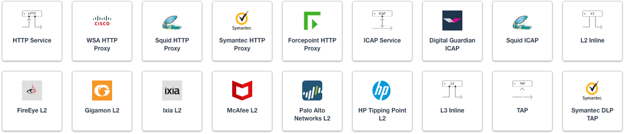
Figure 21: SSL Orchestrator service catalog
For simplicity of this initial topology configuration, security services are defined in the Services chapter. Please navigate to this chapter for complete information on configuration of the various services.
Service Chain List
Service Chains are ordered lists of security devices. Based on environmental requirements, different service chains may contain different re-used sets of services, and different types of traffic can be assigned to different service chains.
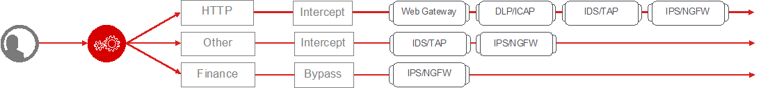
Figure 22: SSL Orchestrator logical security policy and service chaining
Security Policy
Security Policies are the set of rules that govern how traffic is processed in SSL Orchestrator, and the actions a rule can take include,
Whether or not to allow the traffic (Allow or Reject)
Whether or not to decrypt the traffic (Intercept or Bypass)
Which service chain (if any) to pass the traffic through
The Guided Configuration presents an intuitive rule-based, drag-and-drop user interface for the definition of security policies. Note that the default “All Traffic” rule allows and intercepts (decrypts) traffic but does not assign a service chain. To be effective, it is advisable to assign a service chain here.
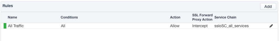
Figure 23: SSL Orchestrator basic security policy
In the background, SSL Orchestrator maintains these security policies as visual per-request policies. If traffic processing is required that exceeds the capabilities of the rule-based user interface, the underlying per-request policy can be managed directly.
Note
Once the per-request policy is manipulated, the rules-based user interface can no longer be used.
The Server Certificate Status Check option inserts additional security policy logic to validate the remote server certificate and return a blocking page to the user if the certificate is untrusted or expired. One or both of the Certificate Response options on the SSL Configuration page (Expire Certificate Response and Untrusted Certificate Response) must be set to ‘ignore’. SSL Orchestrator will “mask” the server certificate’s attributes in order to present a blocking page with a valid forged certificate. For a reverse proxy topology, this option is rarely needed.
Interception Rule
Interception rules are based on the selected topology and define the “listeners”, analogous to LTM virtual servers, that accept and process different types of traffic (ex. TCP, UDP, other). The resulting LTM virtual servers will bind the SSL settings, VLANs, IP addresses, and security policies created in the topology workflow. In the L3 Inbound topology, two use cases exist for how traffic is consumed and processed by SSL Orchestrator. In the Gateway mode, the SSL Orchestrator will sit in the routing path of inbound traffic, but not present target IP addresses. In this case, the destination address of an incoming packet will be that of a device on the other side of the topology, which may be another load balancer or routing path. In the Application mode, the topology behaves like a service, exposing the target IP address and port. In this case, the destination address of an incoming packet will be assigned to this topology. The topology will then NAT the traffic inbound to a pool of internal resources. The configuration of Gateway or Application mode is primarily defined on the Interception Rules page of the topology workflow and detailed below.
Gateway mode
Enable Hide Advanced Setting - this setting will present only the settings needed to configure the reverse proxy topology for gateway mode.
Source Address - this defines a matching source address pattern for ingress traffic flows. The default 0.0.0.0%0/0 pattern matches all inbound traffic (on route domain 0).
Destination Address/Mask - this defines a matching destination address pattern for inbound traffic flows. The default 0.0.0.0%0/0 pattern matches all inbound traffic (on route domain 0). A gateway mode deployment will usually consume traffic on all destination IP addresses (0.0.0.0/0), or some subset of all traffic based on IP subnet mask and/or listening port.
Port - this defines a matching destination port for inbound traffic flows. It may be desirable to only process HTTP port 80 or HTTPS port 443 for example. The default 0 port pattern processes outbound traffic on any port. A gateway mode deployment will usually consume traffic on all destination IP addresses (0.0.0.0/0), or some subset of all traffic based on IP subnet mask and/or listening port.
Access Profile - this defines the security policy that will process traffic based on traffic matching rules. This will default to the previously created security policy but may be changed here to suit other more advanced requirements. If the selected Access Profile was created outside of SSL Orchestrator, the Log Settings step will not appear. You may modify the log settings using TMSH. When the SSL Orchestrator default access profile /Common/ssloDefault_accessProfile is selected, you may modify Log Settings using the SSL Orchestrator > Logs > Settings UI or use TMSH.
VLANs - this defines the client-facing VLANs that this topology will listen on. An SSL Orchestrator topology can listen on multiple VLANs.
SSL Configurations - In gateway mode, multiple SSL configurations can be selected. The BIG-IP will dynamically select the correct SSL configuration based on the incoming TLS Client Hello Server Name Indication (SNI) value from the client.
Client TCP Profile - This defines the specific client TCP profile to use.
Verified Accept - Enable the Verified Accept option if you would like the BIG-IP to send a reset packet in response to a new TCP connection when a virtual server is unavailable. When the Verified Accept option is enabled, the BIG-IP verifies that the pool member is available to accept the connection by sending the server a SYN before responding to the client SYN with a SYN-ACK; enabling this option causes a server-side load balancing decision to be made before the client-side connection setup has completed when the virtual server is available.
[Advanced] Server TCP Profile - This defines the specific server TCP profile to use.
L7 Profile Type - this provides an option to add protocol-specific filters. While not absolutely required, an L7 profile filter will provide additional protocol-specific handling.
L7 Profile - this allows you to select a specific protocol filter. With an L7 Profile Type selected, this allows selection of a pre-defined L7 profile filter.
Application mode
Enable Show Advanced Setting. The Advanced Settings option makes visible the settings that enable Application mode.
Source Address - this defines a matching source address pattern for ingress traffic flows. The default 0.0.0.0%0/0 pattern matches all inbound traffic (on route domain 0).
Destination Address/Mask - this defines a matching destination address for inbound traffic flows. For application mode reverse proxy traffic, this will be a dedicated IP address.
Port - this defines a matching destination port for inbound traffic flows. For application mode reverse proxy traffic, this will correspond with the dedicated IP address as the address-port combination for this application instance.
Access Profile - this defines the security policy that will process traffic based on traffic matching rules. This will default to the previously created security policy but may be changed here to suit other more advanced requirements. If the selected Access Profile was created outside of SSL Orchestrator, the Log Settings step will not appear. You may modify the log settings using TMSH. When the SSL Orchestrator default access profile /Common/ssloDefault_accessProfile is selected, you may modify Log Settings using the SSL Orchestrator > Logs > Settings UI or use TMSH.
VLANs - this defines the client-facing VLANs that this topology will listen on. An SSL Orchestrator topology can listen on multiple VLANs.
Protocol Settings - SSL Configurations - allows setting a custom SSL configuration. For example, to define an HTTP topology, one that only processes unencrypted HTTP traffic on port 80, you would remove the SSL configuration.
Protocol Settings - Client TCP Profile - allows setting a custom client-side TCP profile.
[Advanced] Protocol Settings - Server TCP Profile - allows setting a custom server-side TCP profile.
L7 Profile Type - this provides an option to add protocol-specific filters. While not absolutely required, an L7 profile filter will provide additional protocol-specific handling.
L7 Profile - this allows you to select a specific protocol filter. With an L7 Profile Type selected, this allows selection of a pre-defined L7 profile filter.
[Advanced] Pool - select an existing server pool. In the Application mode, the topology enables NAT to an internal load-balanced pool of resources.
Egress Settings
Egress Settings are now defined per-topology and manage both the gateway route and outbound SNAT settings.
Manage SNAT Settings - enables per-topology instance SNAT settings.
Gateways - enables per-topology instance gateway routing. Options are to use the system default route, to use an existing gateway pool, or to create a new gateway.
Log Settings
Log Settings are defined per-topology. In environments where multiple topologies are deployed, this can help to streamline troubleshooting by reducing debug logging to the affected topology. Multiple discrete logging options are available, however under a reverse proxy topology only the Per-Request Policy and SSL Orchestrator Generic are relevant.
Per-Request Policy - provides log settings for security policy processing. In Debug mode, this log facility produces an enormous amount of traffic, so it is recommended to only set Debug mode for troubleshooting. Otherwise the most appropriate setting is Error to only log error conditions.
SSL Orchestrator Generic - provides log settings for generic SSL Orchestrator processing. If Per-Request Policy logging is set to Error, and SSL Orchestrator Generic is set to Information, only the SSL Orchestrator packet summary will be logged. Otherwise the most appropriate setting is Error to only log error conditions.
Summary
The Summary page presents an expandable list of all of the workflow-configured objects. To expand the details for any given setting, click the corresponding arrow icon on the far right. To edit any given setting, click the corresponding pencil icon. Clicking the pencil icon will send the workflow back to the selected settings page.
Upon successfully deploying the configuration, SSL Orchestrator will now display a Configure view.
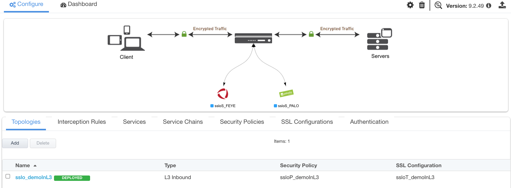
Figure 24: Guided Configuration landing page
The Interception Rules tab shows the listeners that were created per the selected topology.
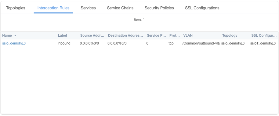
Figure 25: Interception Rules list
In the above:
The single listener defines normal TCP IPv4 traffic for a gateway mode reverse proxy topology.