F5 Application Delivery Controller Solutions > Building the F5 Fabric > Module 1: BIG-IP Device Service Cluster Configuration Source | Edit on
Lab 1: Active/Active ScaleN Clustering Exercise
Configuration of active/active device cluster utilizing multiple traffic groups.
Objective:
- Create a two node cluster, with a traffic groups active on both BIG-IPs.
- Create two standard virtual servers. Both virtual servers must be active on a different BIG-IP in the cluster.
Prerequisites and Notes:
To save some time, both VE images have been provided for you. They are licensed, and have basic network connectivity established on the three VLANs listed below.
1.1 = External Network Interface (WAN Side)
1.2 = Internal network interface (LAN Side)
1.3 = High Availability Network Interface *not yet configured
The following is the IP addressing scheme for every student.
- External:
10.128.10.0/24 - Internal:
10.128.20.0/24 - HA:
192.168.1.0/24
Lab Requirements:
- Configure Floating Self-Ips
- Create HA VLAN
- Create additional Traffic Group
- Build a Device Service Cluster
- Create a pool of web servers
- Create three virtual servers
- Test failover
TASK 1 – Configure Floating Self IP’s
Create Floating Self IPs
Open Chrome on the Windows jump box. Connect to bigip1.
https://10.128.1.245(accept certificate error)- Username:
admin - Password:
admin
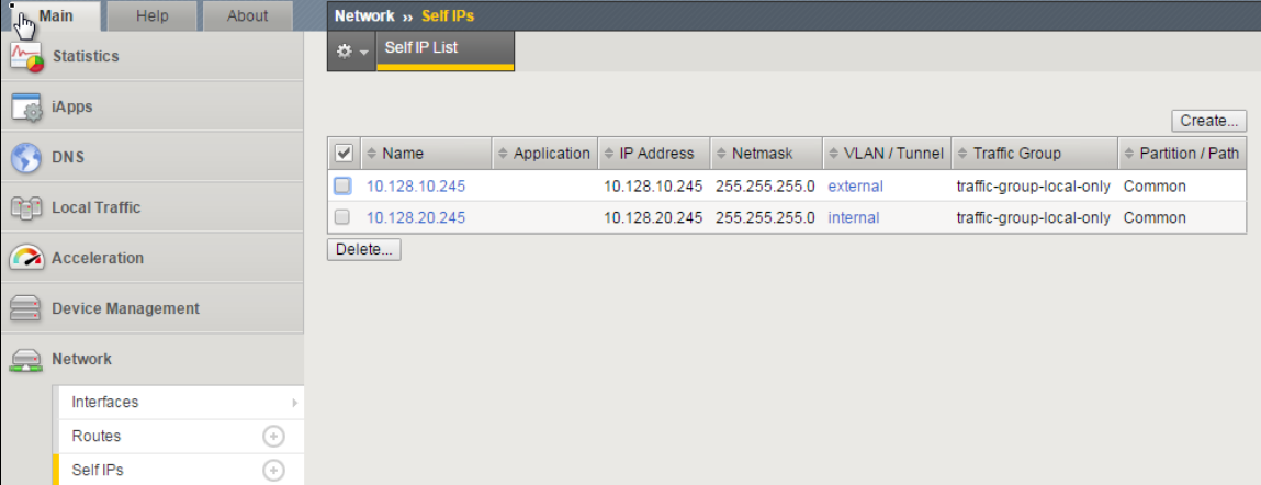
Go to Network -> Self Ips -> Create
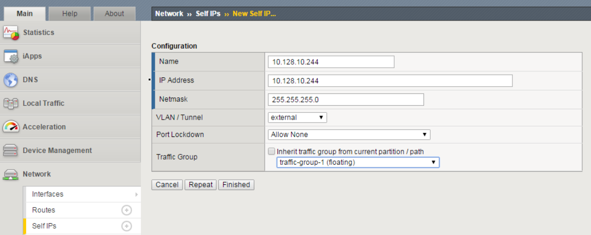
Create a Floating Self IP for External VLAN using the following values
- Name/Address:
10.128.10.244 - Netmask:
255.255.255.0 - Port Lockdown:
Allow None - Traffic group:
traffic-group-1 (floating)
- Name/Address:
Click Finished
Create a Floating Self IP for Internal VLAN using the following values
- Name/Address:
10.128.20.244 - Netmask:
255.255.255.0 - Port Lockdown:
None - Traffic Group:
traffic-group-1 (floating)
- Name/Address:
Click Finished
Note
Although Self IP’s (non-floating) must be created on both F5’s in a cluster (which was already completed for you), the creation of Floating Self IP’s only needs to occur on a single F5, as they will "float" to the other F5 after HA has been successfully completed.
TASK 2 – Create HA VLAN
Create HA VLAN
Go to Network -> VLANs -> VLAN List -> Create
Create a VLAN using the following values:
- Name:
ha - Interface:
1.3 (untagged)
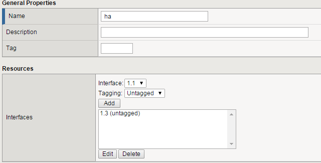
- Name:
Click Finished
Repeat the above steps to create the ha vlan on bigip2
Create one Self IP on **bigip1* and one on bigip2 for HA VLAN*
On bigip1:
Go to Network -> Self IP’s -> Create
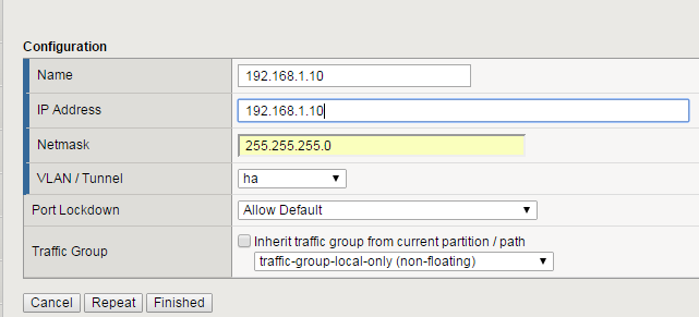
Create a Self IP using the following values:
- Name:
192.168.1.10 - IP Address:
192.168.1.10 - Netmask:
255.255.255.0 - VLAN:
ha - Port Lockdown:
Allow Default - Traffic Group:
traffic-group-local-only (non-floating)
- Name:
Click Finished
On bigip2:
- Go to Network -> Self IP’s -> Create
- Create a Self IP using the following values:
- Name:
192.168.1.11 - IP Address:
192.168.1.11 - Netmask:
255.255.255.0 - VLAN:
ha - Port Lockdown:
Allow Default - Traffic Group:
traffic-group-local-only (non-floating)
- Name:
Note
It is critical the Self IP on each big-ip be set to Allow Default for the ha VLAN. This is because failover communication will be configured to use those IP’s in an upcoming task.
TASK 3 – Create Traffic Groups and Additional Floating Self IP’s
Create 2 new traffic groups on bigip1
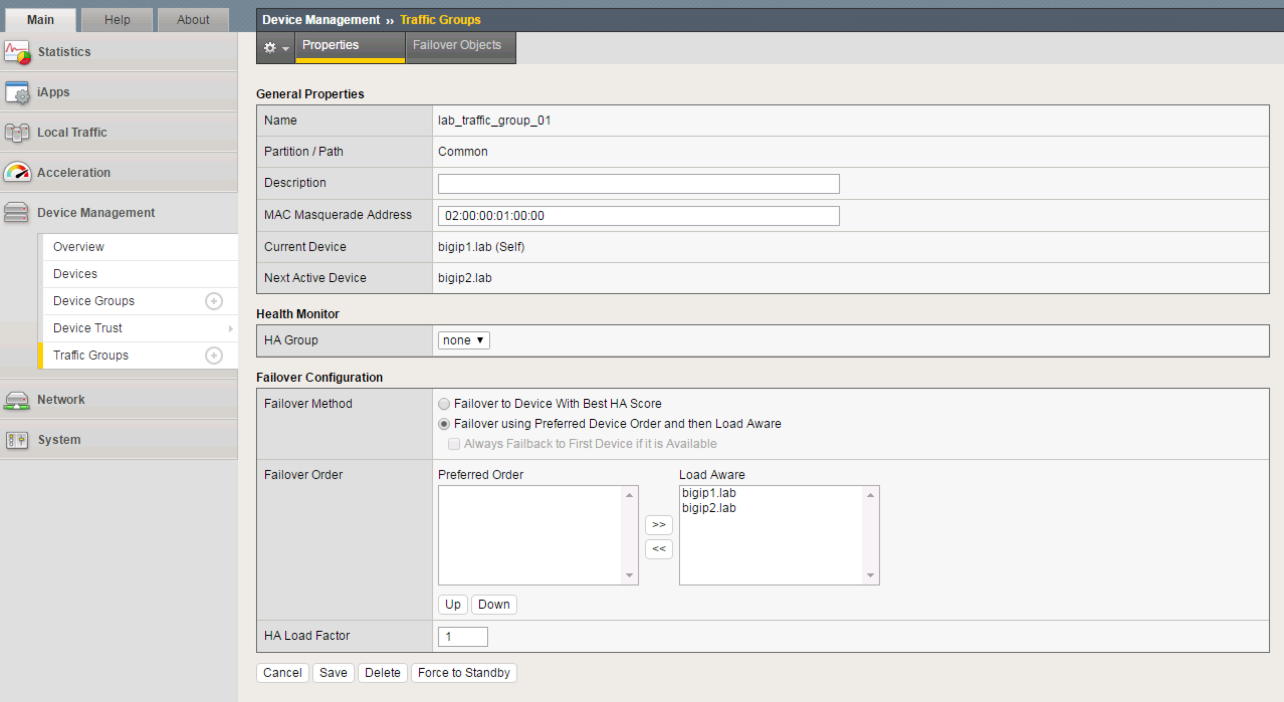
- Go to Device Management -> Traffic Groups -> Create
- Create a new Traffic Group using the following values:
- Name:
lab_traffic_group_01 - MAC Masquerade:
02:00:00:01:00:00 - Failover Method =
Failover using Preferred Device Order and then Load Aware
- Name:
- Click Create Traffic Group
- Go to Device Management -> Traffic Groups -> Create
- Create a new Traffic Group using the following values:
- Name:
lab_traffic_group_02 - MAC Masquerade:
02:00:00:02:00:00 - Failover Method =
Failover using Preferred Device Order and then Load Aware
- Name:
- Click Create Traffic Group
Create additional Floating Self IP’s for the Internal VLAN for each traffic group
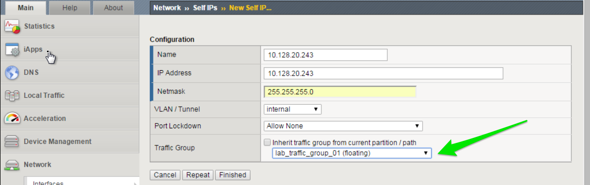
Create a Floating Self IP for Internal VLAN in Traffic Group 1
Go to Network -> Self IP’s -> Create
Create a Floating Self IP using the following values:
- Name:
10.128.20.243 - IP Address:
10.128.20.243 - Netmask:
255.255.255.0 - VLAN:
internal - Port Lockdown:
Allow None - Traffic Group:
lab_traffic_group_01 (floating)
- Name:
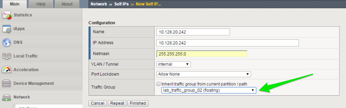
Create a Floating Self IP for Internal VLAN in Traffic Group 2
Go to Network -> Self IP’s -> Create
Create a Floating Self IP using the following values:
- Name:
10.128.20.242 - IP Address:
10.128.20.242 - Netmask:
255.255.255.0 - VLAN:
internal - Port Lockdown:
Allow None - Traffic Group:
lab_traffic_group_02 (floating)
- Name:
TASK 4 – Configure Device Connectivity for HA Communication
Configure Local HA Address
- Go to Device Management -> Devices -> select your device (bigip1)
- Choose ConfigSync tab
- Under Local Address
- Choose the HA address and click Update
Configure Network Failover
- From the Failover Network tab, choose Add
- Add both the Management address as well as the HA VLAN address
Important
Perform both of the above steps on bigip2 as well.
On bigip1, add bigip2 to Peer List
Go to Device Management -> Device Trust -> Device Trust Members
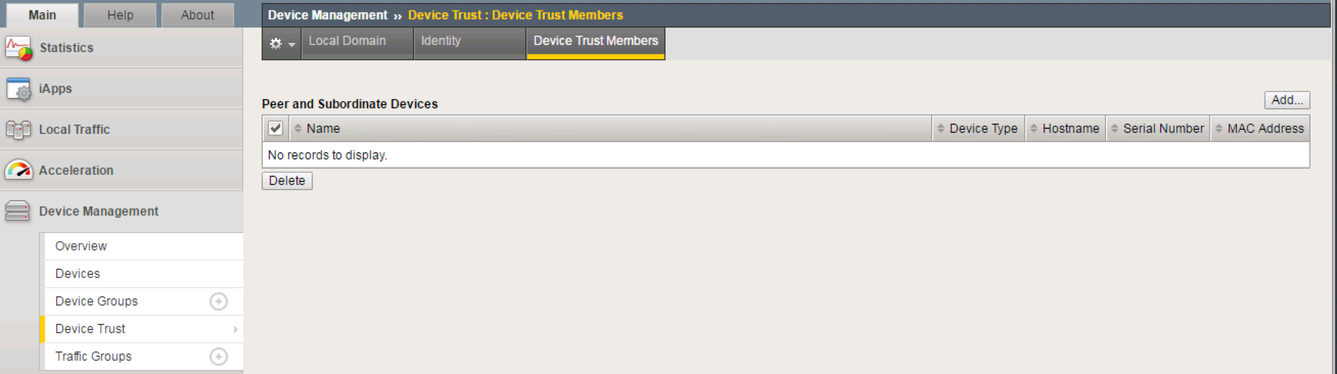
Click Add
Add the second F5’s Management Address
Click Retrieve Device Information
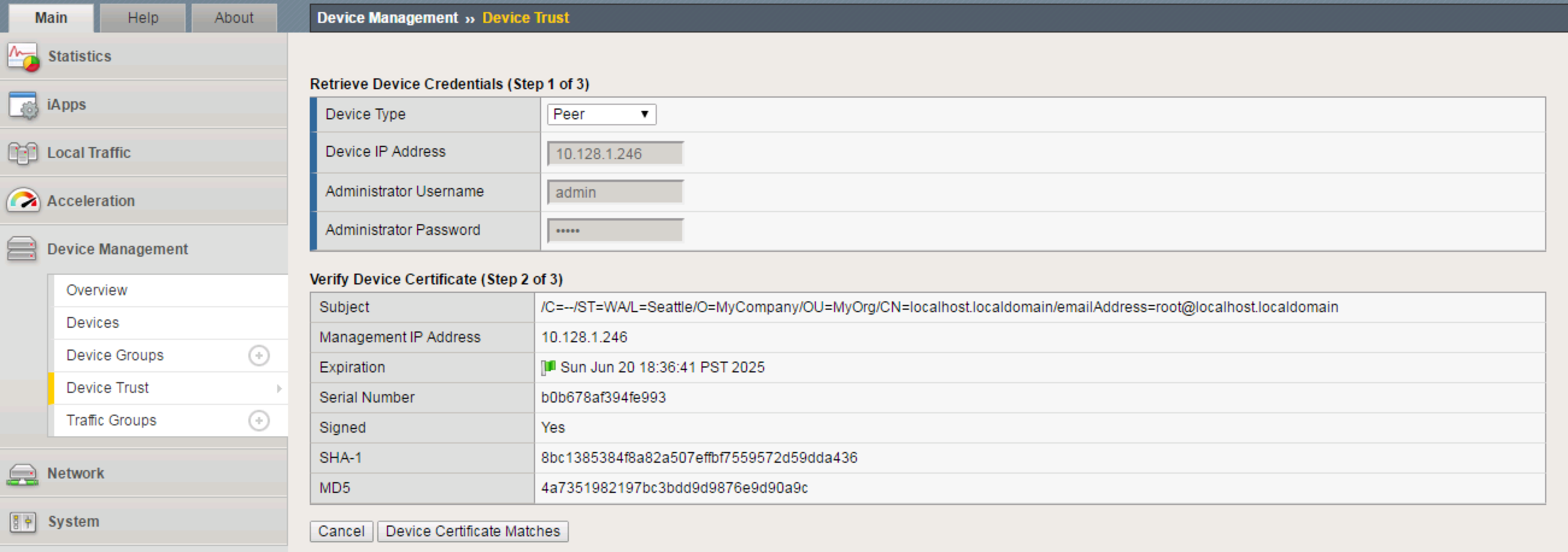
Click Device Certificate Matches
Click Add Device
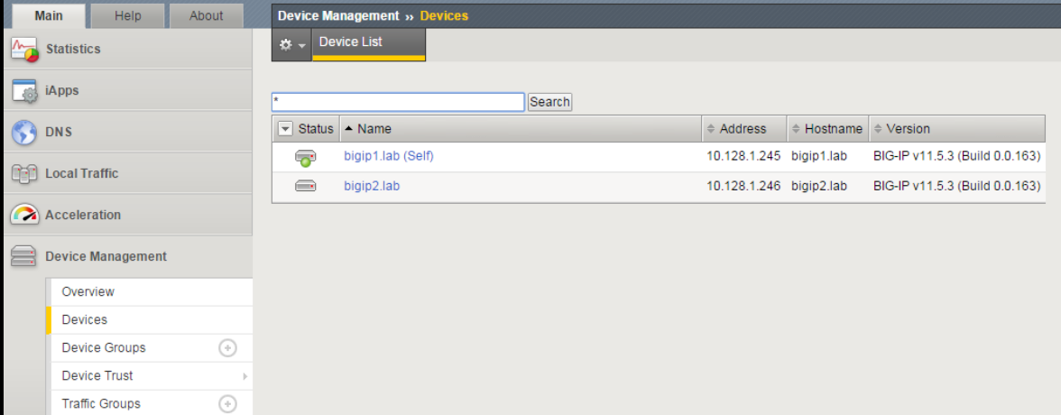
Click on Device Management -> Devices. You will now see both F5’s.
Create Device Group
Go to Device Management -> Device Groups -> Create
Create a Device Group using the following values:
- Name:
device_group_01 - Group Type:
Sync-Failover - Add both devices as Members
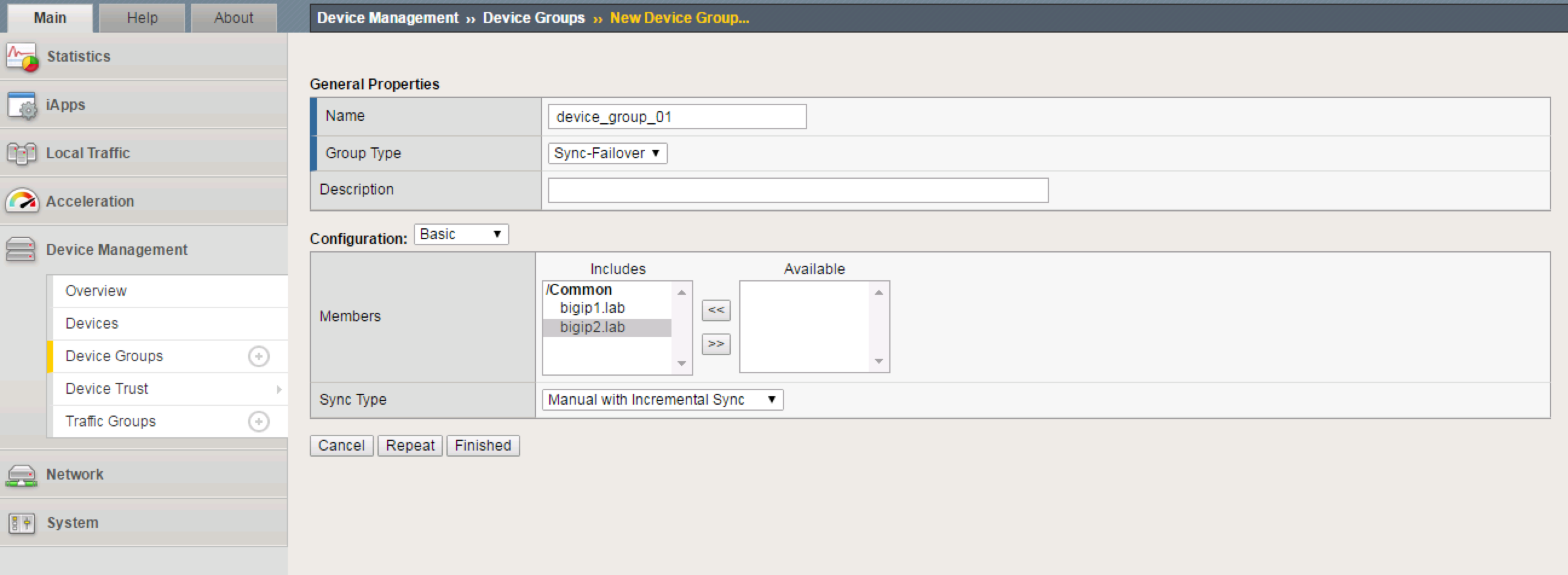
- Name:
Click Finished
Perform the initial configuration sync
Click Awaiting Initial Sync in upper left corner of your screen

Select
bigip1.lab (Self)Choose
Push the selected device configuration to the group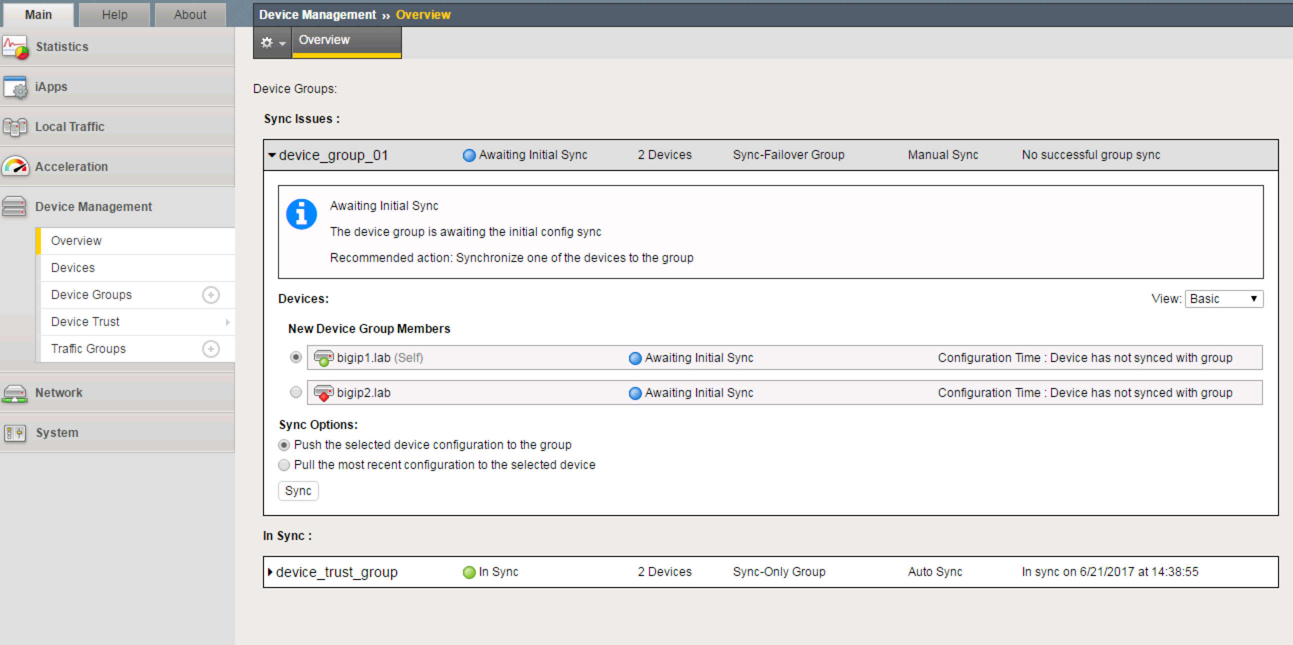
Click Sync. You will notice the change in the upper left status to "In Sync"
TASK 5 – Create Web Server Pool and Virtual Servers
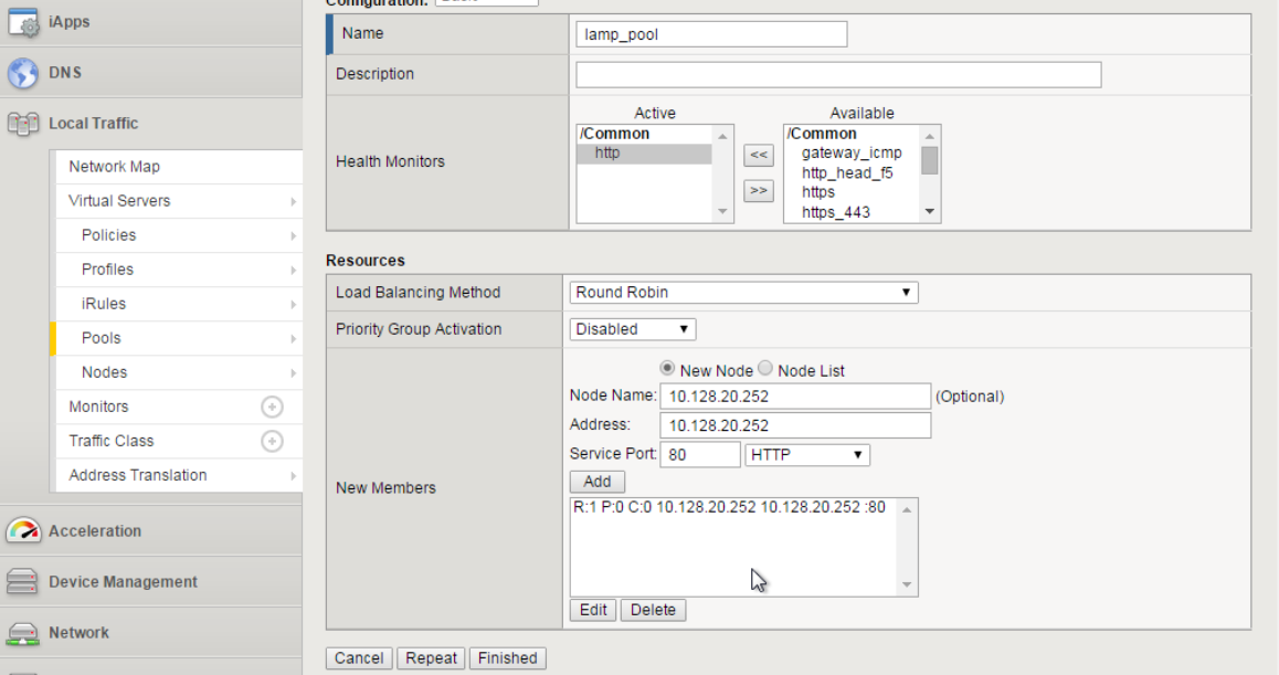
Create a web server pool
Go to Local Traffic -> Pools -> Create
Create a Pool using the following values:
- Name:
lamp_pool - Health Monitor:
http - Add first Node:
- Node Name:
10.128.20.11- Address:10.128.20.11- Port:80 - Add second Node:
- Node Name:
10.128.20.12- Address:10.128.20.12- Port80 - Add third Node:
- Node Name:
10.128.20.13- Address:10.128.20.13- Port80
- Name:
Click Finished.
Create first Virtual Server
- Go to Local Traffic -> Virtual Servers -> Create
- Create a Virtual Server using the following values:
- Name:
http_vs_01 - Destination (Host):
10.128.10.230 - Port
80 - Default Pool:
lamp_pool - Source Address Translation (SNAT):
Auto Map
- Name:
- Click Finished
Create second Virtual Server
Go to Local Traffic -> Virtual Servers -> Create
Create a Virtual Server using the following values:
- Name:
http_vs_02 - Destination (Host):
10.128.10.231 - Port
80 - Default Pool:
lamp_pool - Source Address Translation (SNAT):
Auto Map
- Name:
Click Finished
You should now have two virtual servers created
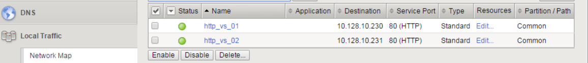
Sync your configuration.
TASK 6 – Configure Virtual Servers for Different Traffic Groups and Simulate Failover
Reconfigure the new Virtual Servers so that they reside in the 2 new traffic groups.
Go to Local Traffic -> Virtual Servers -> Virtual Address List
Click on
10.128.10.230Change the Traffic Group to
lab_traffic_group_01.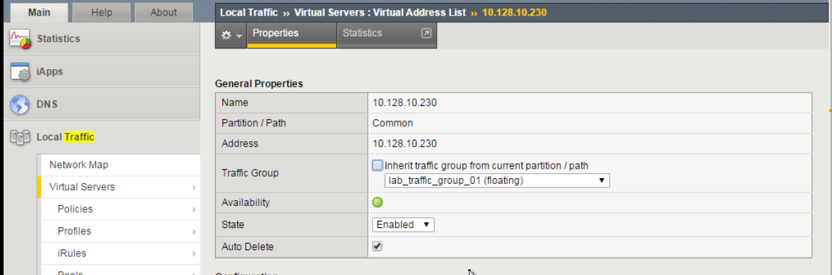
Click Update
Perform the same procedure for
10.128.10.231, but place inlab_traffic_group_02.Sync Configuration
Check which objects are in each Traffic Group
- Go to Device Management -> Traffic Groups
- Select a group, and choose Failover Objects.
Simulate a failover within the Active/Active cluster
Go to Device Management -> Traffic Groups
Take note of which devices are currently servicing each Traffic Group. If 1 device is servicing a particular traffic group, and the other device is servicing another traffic group, you will see that both bigip1 and bigip2 list their status as
ACTIVEin the GUI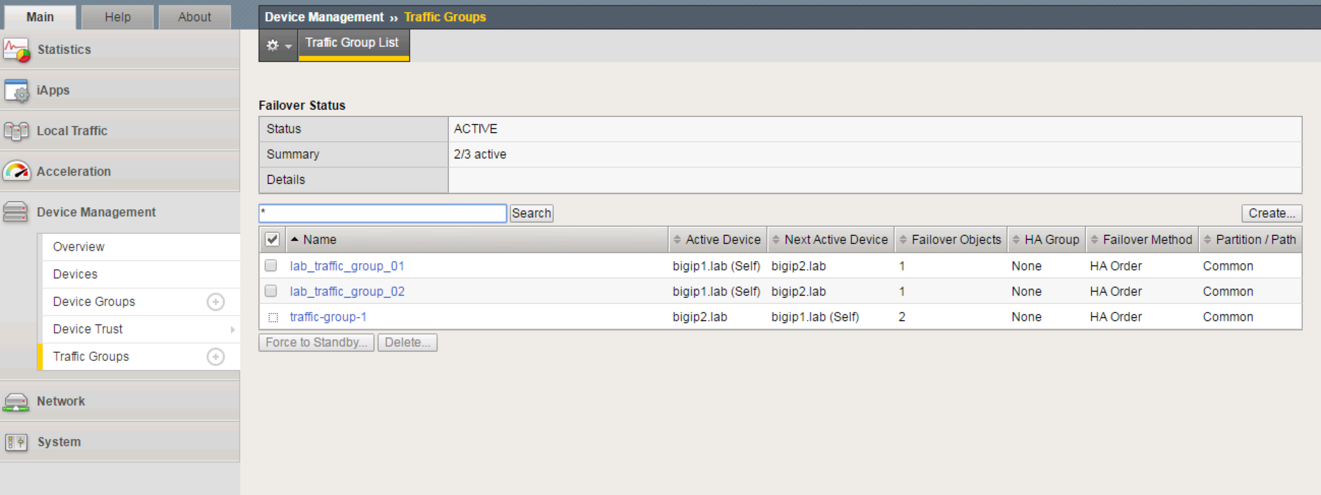
From bigip1, choose any Traffic Group which is currently active on it.
Select Force to Standby to manually fail this traffic group over to bigip2
Note
This is failing over the traffic group only, not the device. When all traffic groups have been failed-over to bigip2, bigip1 will be STANDBY, and bigip2 will be ACTIVE.
Why does bigip1 display as STANDBY when we never failed it over at the device level?
Are all VIP’s still accessible?
What are some practical, real-world examples for what we just configured?