Unofficial - F5 Certification Exam Prep Material > F5 301A - BIG-IP LTM Specialist: Architect, Set-Up & Deploy Exam Study Guide Source | Edit on
Section 2 - Set-up, administer, and secure LTM devices
Objective - 2.01 Distinguish between the management interface configuration and application traffic interface configuration
2.01 - Explain the requirements for management of the LTM devices
https://support.f5.com/csp/article/K7312?sr=29126873
LTM Management
The BIG-IP can be managed through either the TMM switch interfaces or the MGMT interface. However, F5 recommends that you use the management port.
The TMM switch ports are the interfaces that the BIG-IP system uses to send and receive load-balanced traffic.
The system uses the MGMT interface to perform system management functions. The MGMT interface is intended for administrative traffic and cannot be used for load-balanced traffic. Additionally, since no access controls can be applied on the MGMT interface, F5 recommends that you limit network access through the MGMT interface to trusted traffic. For security reasons, the MGMT interface should be connected to only a secure, management-only network, such as one that uses an RFC1918 private IP address space. If you do not have a trusted and secure management network, F5 recommends that you do not use the MGMT interface, and that you grant administrative access through the TMM switch interfaces or the local serial console.
Note: In BIG-IP versions earlier than 11.2.0, you must assign an IPv4 address to the management port. Beginning in BIG-IP 11.2.0, you can assign either an IPv4 or IPv6 to the management port.
https://support.f5.com/kb/en-us/products/big-ip_ltm/manuals/product/f5-plat-hw-essentials/1.html
Serial Console Connection
In the event that network access is impaired or not yet configured, the serial console might be the only way to access your BIG-IP® system.
Important: You should perform all BIG-IP software installations and upgrades using the serial console, as these procedures require reboots, in which network connectivity is lost temporarily.
Note: If you cannot see or read output on the serial console, make sure that the baud rate is set to 19200.
2.01 - Explain the differences between the flow of management and application traffic
https://support.f5.com/csp/article/K7312
The BIG-IP system uses the following two network connection entry points:
- Traffic Management Microkernel (TMM) switch interfaces
- Management interface
Either the TMM switch interfaces or the management interface can provide administrative access to the BIG-IP system. However, F5 recommends that you use the management interface.
The TMM switch ports are the interfaces that the BIG-IP system uses to send and receive load-balanced traffic.
The system uses the management interface to perform system management functions. The management interface is intended for administrative traffic and cannot be used for load-balanced traffic. Additionally, since there are limited access controls that can be applied to the management interface, F5 recommends that you limit network access through the management interface to trusted traffic. For security reasons, the management interface should only be connected to a secure, management-only network, such as one that uses an RFC1918 private IP address space. If you do not have a trusted and secure management network, F5 recommends that you do not use the management interface and that you grant administrative access through the TMM switch interfaces or the local serial console.
2.01 - Explain how to configure management connectivity options: AOM, serial console, USB & Management Ethernet Port
https://support.f5.com/csp/article/K13117?sr=42528406
USB
On rare occasions, you may be required to perform a clean installation of BIG-IP 11.x. During a clean installation, all mass-storage devices are wiped, therefore restoring the BIG-IP system to its factory defaults. In addition, a clean installation allows you to reinstall a BIG-IP unit that no longer boots from any of its boot locations.
You should choose an installation method based on the equipment available to you, and whether you have physical access to the system that requires reinstalling. Choose one of the following installation methods, which are listed in order of preference:
USB DVD-ROM drive
Note: F5 recommends that you perform a clean installation by using a USB DVD-ROM drive, as this is the simplest and most reliable of all the installation methods.
USB thumb drive
Burn the product ISO image to a DVD.
Image the USB thumb drive using the product ISO image file.
Installing the software
- Connect to the BIG-IP system serial console.
- Depending on the choice you made in the previous procedure, perform one of the following actions:
- Connect the USB DVD-ROM drive to the F5 system and load the disc you burned with the product ISO image.
- Connect the USB thumb drive to the F5 system.
- Reboot the BIG-IP system. If the F5 system cannot reboot, power cycle the BIG-IP system.
Note: Upon completion of this step, regardless of the installation method, the BIG-IP system boots into the Maintenance Operating System (MOS).
- The MOS asks you to specify the type of terminal you are using. If you do not know what to specify, press Enter. The default setting (vt100) is fine in most cases.
- If you have booted the F5 system from a USB device, the system may display a manufacturing installation dialog.
- Press Ctrl+C to exit the dialog.
- Continue with step 8 if you have booted the F5 system from a USB removable media containing a BIG-IP 11.0.0 image, but you want to perform a custom installation using the diskinit and image2disk utilities. Otherwise, to reinstall the system according to the manufacturing installation plan displayed in the output, press Enter and skip to step 10.
7. To wipe all mass-storage devices inside the BIG-IP system, type the following command:
diskinit --style volumes

Important: Do not omit the –style option; if you omit it, the system wipes the drives but does not reformat them.
- The diskinit utility asks whether you want to proceed wiping the drives. To continue, type y and press Enter. Otherwise, type n and press Enter.
Important: Confirming this operation destroys all data on the system. Do not proceed with this step if you have data that needs to be recovered from the system. Using the MOS, you may be able to manually mount a partition or volume and recover such data.
- Install the software using one of the following methods:
If you are using a USB DVD-ROM drive or a USB thumb drive, use the following command:
image2disk --format=volumes --nosaveconfig --nosavelicense
If you are using a PXE server, use the following command syntax:
image2disk --format=volumes --nosaveconfig --nosavelicense
http://<SERVER_IP>/<PATH>
For example, to install BIG-IP 11.x on HD1.1 using the http server configured in the previous procedure, type the following command:
image2disk --format=volumes --nosaveconfig --nosavelicense
http://192.168.1.1/SOL13117
Note: BIG-IP 11.x cannot be installed on a CompactFlash media drive; you must use boot locations on the system’s hard drive.
Note: You must specify the –nosaveconfig option, as the system does not have a configuration to save.
Note: If you are using a USB DVD-ROM drive or a USB thumb drive, you do not need to specify an installation repository, as the image2disk utility automatically finds and defaults to /cdserver.
Note: For more information about the image2disk utility, refer to the Help screen by using the image2disk –h command.
- Once the installation has completed, disconnect any removable media from the BIG-IP system.
11. To restart the system, type the following command:
reboot
The system boots from the location you have just reinstalled.
https://support.f5.com/csp/article/K7683?sr=42527838
Serial Console
You can administer a BIG-IP system by using a null modem cable to connect a management system that runs a terminal emulator program to the BIG-IP serial port. To connect to the BIG-IP system using the serial port, you must have a DB9 null modem cable and a VT100-capable terminal emulator available on the management system.
To configure a serial terminal console for the BIG-IP system, perform the following procedure:
- Connect the null modem cable to the console port on the BIG-IP system.
- Connect the null modem cable to a serial port on the management system with the terminal emulator.
- Configure the serial terminal emulator settings according to the following table:
| Setting | Value |
|---|---|
| Bits per second [baud] | 19200 |
| Data bits | 8 |
| Parity | None |
| Stop bit | 1 |
| Flow control | None |
- Turn on the BIG-IP system.
When the BIG-IP system starts up with the console working correctly, the system start-up sequence displays, and then the sequence completes with a BIG-IP system login prompt. If garbled text displays on the console, you may be required to change the baud of the serial console port using the LCD panel on the BIG-IP system.
https://support.f5.com/csp/article/K15040?sr=42528282
Management Ethernet Port
The management port on a BIG-IP system provides administrative access to the system out-of-band of the application traffic. This allows you to restrict administrative access to an internal secure network. You can display and configure the management IP address for the BIG-IP system using the Configuration utility, the command line, and the LCD panel.
Configuring the management IP address using the Configuration utility, command line, or LCD panel
You can configure the management IP address using the Configuration utility, the tmsh utility, the config command, or the LCD panel. To do so, perform one of the following procedures:
Impact of procedure: Changing the management IP address will disconnect you from the BIG-IP system if you are connected through the management port.
Configuring the management IP address using the Configuration utility
- Log in to the Configuration utility.
- Navigate to System > Platform.
- In the Management Port section, configure the IP address, network mask, and management route.
- To save the changes, click Update.
Configuring the management IP address using the tmsh utility
1. Log in to the Traffic Management Shell (tmsh) by typing the following command:
tmsh
2. To configure the management IP address, use the following syntax:
create /sys management-ip [ip address/netmask]

or

create /sys management-ip [ip addres/prefixlen]

For example:

create /sys management-ip 192.168.1.245/255.255.255.0

or

create /sys management-ip 192.168.1.245/24
3. To configure a default management gateway, use the following syntax:
create /sys management-route default gateway <gateway ip address>

For example:

create /sys management-route default gateway 192.168.1.254
4. Save the changes by typing the following command:
save /sys config partitions all
Configuring the management IP address using the config command
- Log in to the command line of the BIG-IP system.
2. Enter the F5 Management Port Setup Utility by typing the following command:
config
- To configure the management port, type the appropriate IP address, netmask, and management route in the screens that follow.
Configuring the management IP address using the LCD panel
- Press the X button to activate Menu mode for the LCD.
- Use the arrow keys to select System, and press the Check button.
- To select Management, press the Check button.
- To select Mgmt IP, press the Check button.
- Enter your management IP address using the arrow keys, and press the Check button.
- Use the arrow keys to select Mgmt Mask, and press the Check button.
- Enter the netmask using the arrow keys, and press the Check button.
- Use the arrow keys to select Mgmt Gateway, and press the Check button.
- Enter your default route using the arrow keys, and press the Check button.
If you do not have a default route, enter 0.0.0.0.
- Use the arrow keys to select Commit, and press the Check button.
- To select OK, press the Check button.
https://support.f5.com/csp/article/K14595
AOM
Always-On Management (AOM) is a separate subsystem that provides lights-out management for the BIG-IP system by using the 10/100/1000 Ethernet management port over secure shell (SSH), or by using the serial console.
AOM allows you to manage BIG-IP platforms using SSH (most platforms) or the serial console, even if the Host subsystem is turned off. The BIG-IP Host subsystem and the AOM subsystem operate independently. If AOM is reset or fails, the BIG-IP Host subsystem continues to operate and there is no interruption to load-balanced traffic. AOM is always turned on when power is supplied to the platform. If the BIG-IP Host subsystem stops responding, you can use the AOM Command Menu to reset it.
Configuring AOM network access
To configure AOM so that it can be accessed over the network, perform the following procedure:
Impact of procedure: Performing the following procedure should not have a negative impact on your system.
- Connect the serial console to the CONSOLE port.
2. Display the AOM command menu by typing the following key sequence:
Esc (
The AOM command menu displays as follows:
AOM Command Menu:

B --- Set console baud rate

I --- Display platform information

P --- Power on/off host subsystem

R --- Reset host subsystem

N --- Configure AOM network

S --- Configure SSH Server

A --- Reset AOM

E --- Error report

Q --- Quit menu and return to console
- To configure network access, press the N key.
The AOM management network configurator screen appears.
- Complete the network configurator screens.
Important: The AOM IP address must be different than the BIG-IP management address, but on the same IP subnet.
To disable the network configuration, re-run the N —Configure AOM network option, and enter 0.0.0.0 for the IP address.
Objective - 2.02 Given a network diagram, determine the appropriate network and system settings (i.e., VLANs, selfIPs, trunks, routes, NTP servers, DNS servers, SNMP receivers and syslog servers)
2.02 - Explain the requirements for self IPs (including port lockdown)
https://support.f5.com/kb/en-us/products/big-ip_ltm/manuals/product/tmos-concepts-11-5-0/13.html
Self IPs
It is when you initially run the Setup utility on a BIG-IP system that you normally create any static and floating self IP addresses and assign them to VLANs. However, if you want to create additional self IP addresses later, you can do so using the Configuration utility.
Note: Only users with either the Administrator or Resource Administrator user role can create and manage self IP addresses.
Note: A self IP address can be in either IPv4 or IPv6 format.
IP address
A self IP address, combined with a netmask, typically represents a range of host IP addresses in a VLAN. If you are assigning a self IP address to a VLAN group, the self IP address represents the range of self IP addresses assigned to the VLANs in that group.
Netmask
When you specify a netmask for a self IP address, the self IP address can represent a range of IP addresses, rather than a single host address. For example, a self IP address of 10.0.0.100 can represent several host IP addresses if you specify a netmask of 255.255.0.0.
VLAN/Tunnel assignment
You assign a unique self IP address to a specific VLAN or a VLAN group:
- Assigning a self IP address to a VLAN
The self IP address that you assign to a VLAN should represent an address space that includes the self IP addresses of the hosts that the VLAN contains. For example, if the address of one destination server in a VLAN is 10.0.0.1 and the address of another server in the VLAN is 10.0.0.2, you could assign a self IP address of 10.0.0.100, with a netmask of 255.255.0.0, to the VLAN.
- Assigning a self IP address to a VLAN group
The self IP address that you assign to a VLAN group should represent an address space that includes the self IP addresses of the VLANs that you assigned to the group. For example, if the self IP address of one VLAN in a VLAN group is 10.0.20.100 and the address of the other VLAN in a VLAN group is 10.0.30.100,you could assign an address of 10.0.0.100, with a netmask of 255.255.0.0, to the VLAN group.
The VLAN/Tunnel list in the BIG-IP Configuration utility displays the names of all existing VLANs and VLAN groups.
Port lockdown
Each self IP address has a feature known as port lockdown. Port lockdown is a security feature that allows you to specify particular UDP and TCP protocols and services from which the self IP address can accept traffic. By default, a self IP address accepts traffic from these protocols and services:
- For UDP, the allowed protocols and services are: DNS (53), SNMP (161), RIP (520)
- For TCP, the allowed protocols and services are: SSH (22), DNS (53), SNMP (161), HTTPS (443), 4353 (iQuery)
If you do not want to use the default setting (Allow Default), you can configure port lockdown to allow either all UDP and TCP protocols and services (Allow All), no UDP protocols and services (Allow None), or only those that you specify (Allow Custom).
Traffic groups
If you want the self IP address to be a floating IP address, that is, an address shared between two or more BIG-IP devices in a device group, you can assign a floating traffic group to the self IP address. A floating traffic group causes the self IP address to become a floating self IP address.
A floating self IP address ensures that application traffic reaches its destination. More specifically, a floating self IP address enables a source node to successfully send a request, and a destination node to successfully send a response, when the relevant BIG-IP device is unavailable.
If you want the self IP address to be a static (non-floating) IP address (used mostly for standalone devices), you can assign a non-floating traffic group to the self IP address. A non-floating traffic group causes the self IP address to become a non-floating self IP address. An example of a non-floating self IP address is the address that you assign to the default VLAN named HA, which is used strictly to process failover communications between BIG-IP devices, instead of processing application traffic.
2.02 - Explain routing requirements for management and application traffic (including route domains and IPv6)
https://support.f5.com/csp/article/K13284?sr=42499558
The Traffic Management Microkernel (TMM) controls all of the BIG-IP switch ports (TMM interfaces), and the underlying Linux operating system controls the BIG-IP management interface. The management interface processes only administrative traffic. The TMM interfaces process both application traffic and administrative traffic.
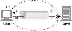
Inbound administrative traffic
The Linux operation system processes inbound traffic sent to the BIG-IP management IP address and arriving on the management interface. Inbound connections sent to the BIG-IP self IP addresses that arrive on a TMM interface are processed by TMM. If the self IP address is configured to allow a connection to the destination service port, TMM hands the connection off to the Linux operating system, which then processes the connection request. By default, the BIG-IP system uses Auto Last Hop to return response traffic to a remote host. Auto Last Hop returns response traffic to the MAC address of the device from which the traffic last traversed before reaching the BIG-IP system.
Note: Beginning in BIG-IP 14.1.0, the Auto Last Hop feature is no longer available on the BIG-IP management interface. For more information, refer to K55225090: BIG-IP VE no longer supports Auto Last Hop for management connections.
Outbound administrative traffic
The Linux operating system processes outbound traffic sent from the BIG-IP system by administrative applications, such as SNMP, SMTP, SSH, and NTP. These connections may use either the management address or a self IP address as the source address. The BIG-IP system compares the destination address to the routing table to determine the interface through which the BIG-IP system routes the traffic.
BIG-IP routing tables
The BIG-IP routing table consists of a combination of routing subtables. A subtable for management routes, and a subtable for TMM routes. Routes in the TMM subtable are defined with a lower metric than routes in the management subtable. As a result, if an equally specific route exists as both a TMM route and a management route, the system will prefer the TMM route. This also applies if the only defined management route is a default gateway, the system will prefer the TMM default gateway.
TMM switch routes are routes that the BIG-IP system uses to forward traffic through the TMM switch interfaces instead of through the management interface. Traffic sourced from a TMM (self IP) address will always use the most specific matching TMM route. Traffic sourced from a TMM address will never use a management route. When TMM is not running, the TMM addresses are not available, and all TMM routes are removed. As a result, when TMM is not running, all outbound administrative traffic uses the most specific matching management route.
The BIG-IP system uses management routes to forward traffic through the management interface.
https://support.f5.com/csp/article/K84417414
Route domains
Route domains are designed to overcome the problem of overlapping network IP address spaces. Because of this design, forwarding traffic between route domains is limited.
Description
One intended route domain implementation would be when the BIG-IP system hosts multiple tenants that use the same private IP address space to configure their networking devices. In this case, route domains allow the hosting BIG-IP system to use the same IP address space for multiple tenants, while preventing direct access between the tenants.
You can allow access between route domains in a limited capacity by using parent-child relationships and strict isolation.
Parent-child relationship
When you create a route domain, you can associate a parent route domain. When the BIG-IP system is unable to find a necessary route in the child domain, the system can then search an associated parent route domain for a possible route. The default associated route domain is None.
Strict isolation
When enabled, strict isolation specifies whether the system enforces cross-routing restrictions. When enabled, routes cannot cross-route domain boundaries; they are strictly isolated to the current route domain. The default setting is Enabled. When disabled, a route can cross-route domains. For example, you can add a route to the routing table where the destination is 10.0.0.0%20 (route domain 20) and the gateway is 172.27.84.29%32 (route domain 32).
Note: When strict isolation is enabled on a route domain, the BIG-IP system allows traffic forwarding from that route domain to the specified parent route domain only. To enforce strict isolation between parent-child route domains, you must enable the strict isolation feature on both the child and the parent route domains.
VLANs
Route domains may not be the proper choice if the intended use does not involve overlapping IP address spaces. Virtual Local Area Networks (VLAN) serve as a logical separation of hosts using the same IP address space. Unlike route domains, the BIG-IP system can forward traffic between VLANs with simple modifications to the routing table.
https://support.f5.com/csp/article/K7267
IPV6
The BIG-IP is a native IPV6 device.
In BIG-IP versions prior to 11.0.0, there is no option in the Configuration utility to specify an IPv6 default route. The default configuration when creating network routes on the BIG-IP system is for IPv4. To specify a default route for an IPv6 address, you must specify both a destination network that uses the route, and a netmask value. Otherwise, the route will be added to the BIG-IP system configuration as an IPv4 default route pointing to an IPv6 gateway.
To specify an IPv6 default route on the BIG-IP system using the Configuration utility, perform the following procedure:
- Log in to the Configuration utility.
- Navigate to Network > Routes.
- Click Add.
- From the Type menu, click Route.
- Specify :: as the Destination.
- Specify :: as the Netmask.
- From the Resource list, click Use Gateway.
- In the box, type the IPv6 IP address.
- Click Finished.
To specify an IPv6 default route on the BIG-IP system using the Traffic Management Shell (tmsh), perform the following procedure:
1. Log in to the tmsh utility by typing the following command:
tmsh
2. Create the IPv6 default route using the following command syntax:
create /net route default-inet6 gw <ipv6 gw address>
Note: A corresponding self IP address residing in the same network of the IPv6 gateway must exist to create the IPv6 route gateway.
For example:

create /net route default-inet6 gw fd00:9:0:0:0:0:0:2
3. Save the configuration changes by typing the following command:
save /sys config
4. To exit the tmsh utility, type the following command:
quit
2.02 - Explain the effect of system time on LTM devices
https://support.f5.com/csp/article/K10240?sr=29127185
NTP
Having the correct system time set on your BIG-IP devices is critical for many different administrative functions. Time stamping for logging is all based on system time. SSL certificates could have issues with the expiration dates. In HA environments if the system time is not set correctly between the units in the HA configuration the systems may not be able to sync configs.
When the BIG-IP system clock is not showing the correct timezone, or the date and time is not synchronized correctly, this could be caused by incorrect NTP configuration or a communication issue with a valid NTP peer server. Remember that even if you have the NTP settings correct in the BIG-IP system it may not be able to reach the NTP if there is an up-stream Firewall or other network restrictions.
Network Time Protocol (NTP)
NTP is a protocol for synchronizing the clocks of computer systems over the network. On BIG-IP systems, accurate timestamps are essential to guarantee the correct behavior of a number of features. While in most cases it is sufficient to configure a couple of time servers that the BIG-IP system will use to update its system time, it is also possible to define more advanced NTP configurations on the BIG-IP system.
Objective - 2.03 Explain how to configure remote authentication and multiple administration roles on the LTM device
2.03 - Explain the mapping between remote users and remote role groups
Remote authentication and authorization of BIG-IP user accounts
The BIG-IP system includes a comprehensive solution for managing BIG-IP administrative accounts on your network. With this solution, you can:
Use a remote server to store BIG-IP system user accounts.
The BIG-IP system includes support for using a remote authentication server to store BIG-IP system user accounts. After creating BIG-IP system accounts on the remote server (using the server vendor’s instructions), you can configure the BIG-IP system to use remote user authentication and authorization (access control) for that server type.
Assign group-based access.
The BIG-IP system includes an optional feature known as remote role groups. With the remote role groups feature, you can use existing group definitions on the remote server to define the access control properties for users in a group. This feature not only provides more granularity in assigning user privileges, but also removes any need to duplicate remote user accounts on the BIG-IP system for the purpose of assigning those privileges.
Propagate a set of authorization data to multiple BIG-IP systems.
The BIG-IP system includes a tool for propagating BIG-IP system configuration data to multiple BIG-IP devices on the network. This tool is known as the Single Configuration File (SCF) feature.
2.03 - Explain the options for partition access and terminal access
Partition Access
A user role defines the access level that a user has for each object in the users assigned partition. An access level refers to the type of task that a user can perform on an object. Possible access levels are:
- Write
Grants full access, that is, the ability to create, modify, enable and disable, and delete an object.
- Update
Grants the ability to modify, enable, and disable an object.
- Enable/disable
Grants the ability to enable or disable an object.
- Read
Grants the ability to view an object.
Terminal Access
Specifies the level of access to the BIG-IP system command line interface. Possible values are: Disabled and Advanced shell.
Users with the Administrator or Resource Administrator role assigned to their accounts can have advanced shell access, that is, permission to use all BIG-IP system command line utilities, as well as any Linux commands.
Objective - 2.04 Explain the uses of administrative partitions
2.04 - Explain the relationship between route domains, user roles and administrative partitions
Administrative partitions
When you create configurable objects for the BIG-IP system, you have the option of putting those objects into administrative partitions. An administrative partition is a logical container of BIG-IP system objects such as virtual servers, pools, and monitors. When you first install the BIG-IP system, a default partition already exists named Common.
By putting objects into partitions, you establish a finer granularity of access control. Rather than having control over all resources on the BIG-IP system or no resources whatsoever, users with certain permissions can control resources within a designated partition only. For example, users with the role of Operator can mark nodes up or down, but can only mark those nodes that reside within their designated partition.
User accounts are another type of object that you can put into a partition. You put user accounts into administrative partitions strictly for the purpose of giving other users administrative access to those accounts. For example, you can put user accounts into partition B, and then assign a set of permissions (known as a user role) to user Jane so that she is allowed to modify user accounts in partition B.
Each user account on the BIG-IP system has a property known as Partition Access. The Partition Access property defines the partitions that the user can access. A user account can have access to either one partition or all partitions. Access to all partitions is known as universal access.
This figure shows how partition access can differ for different user accounts on the BIG-IP system.
In this example, the BIG-IP system objects reside in multiple partitions. Note that user accounts are also a type of BIG-IP system object, and as such, reside in a partition named Users. (Although you are not required to group user accounts together in a separate partition, for security purposes F5 highly recommends that you do so.)
To continue with the example, each user account in partition Users has access to specific, but different, partitions. Note that user accounts sjones, cjohnson, and gnelson can access one partition only, while the tbrown account has universal access.
To summarize, an administrative partition defines a set of objects, including user accounts, that other administrative users can potentially manage. This gives computing organizations greater control over user access to specific objects on the BIG-IP system.
Effect of user roles on objects within partitions
A user role defines the access level that a user has for each object in the user’s assigned partition. An access level refers to the type of task that a user can perform on an object. Possible access levels are:
Write
Grants full access: that is, the ability to create, modify, enable and disable, and delete an object.
Update
Grants the ability to modify, enable, and disable an object.
Enable/disable
Grants the ability to enable or disable an object.
Read
Grants the ability to view an object.
2.04 - Explain the options for partition access and terminal access
Partition Access
A user role defines the access level that a user has for each object in the users assigned partition. An access level refers to the type of task that a user can perform on an object. Possible access levels are:
- Write
Grants full access, that is, the ability to create, modify, enable and disable, and delete an object.
- Update
Grants the ability to modify, enable, and disable an object.
- Enable/disable
Grants the ability to enable or disable an object.
- Read
Grants the ability to view an object.
Terminal Access
Specifies the level of access to the BIG-IP system command line interface. Possible values are: Disabled and Advanced shell.
Users with the Administrator or Resource Administrator role assigned to their accounts can have advanced shell access, that is, permission to use all BIG-IP system command line utilities, as well as any Linux commands.
Objective - 2.05 Given a scenario, determine an appropriate high availability configuration (i.e., failsafe, failover and timers)
2.05 - Explain how the score is calculated for HA groups
Specifying the HA capacity of a device
Before you perform this task, verify that this device is a member of a device group and that the device group contains three or more devices.
You perform this task when you have more than one type of hardware platform in a device group and you want to configure load-aware failover. Load-aware failover ensures that the BIG-IP system can intelligently select the next-active device for each active traffic group in the device group when failover occurs. As part of configuring load-aware failover, you define an HA capacity to establish the amount of computing resource that the device provides relative to other devices in the device group.
Note: If all devices in the device group are the same hardware platform, you can skip this task.
- On the Main tab, click Device Management > Devices. This displays a list of device objects discovered by the local device.
- In the Name column, click the name of the device for which you want to view properties. This displays a table of properties for the device.
- In the HA Capacity field, type a relative numeric value. You need to configure this setting only when you have varying types of hardware platforms in a device group and you want to configure load-aware failover. The value you specify represents the relative capacity of the device to process application traffic compared to the other devices in the device group.
Important: If you configure this setting, you must configure the setting on every device in the device group.
If this device has half the capacity of a second device and a third of the capacity of a third device in the device group, you can specify a value of 100 for this device, 200 for the second device, and 300 for the third device. When choosing the next active device for a traffic group, the system considers the capacity that you specified for this device.
- Click Update.
After you perform this task, the BIG-IP system uses the HA Capacity value to calculate the current utilization of the local device, to determine the next-active device for failover of other traffic groups in the device group.
Specifying an HA load factor for a traffic group
You perform this task when you want to specify the relative application load for an existing traffic group, for the purpose of configuring load-aware failover. Load-aware failover ensures that the BIG-IP system can intelligently select the next-active device for each active traffic group in the device group when failover occurs. When you configure load-aware failover, you define an application traffic load (known as an HA load factor) for a traffic group to establish the amount of computing resource that an active traffic group uses relative to other active traffic groups.
- On the Main tab, click Device Management > Traffic Groups.
- In the Name column, click the name of a traffic group. This displays the properties of the traffic group.
- From the Failover Methods list, select Load Aware. This displays the HA Load Factor setting.
- In the HA Load Factor field, specify a value that represents the application load for this traffic group relative to other active traffic groups on the local device.
Important: If you configure this setting, you must configure the setting on every traffic group in the device group.
- Click Update.
After performing this task, the BIG-IP system uses the HA Load Factor value as a factor in calculating the current utilization of the local device, to determine whether this device should be the next-active device for failover of other traffic groups in the device group.
Implementation Results
For this implementation example, the load-aware configuration now consists of both a user-specified relative high availability (HA) hardware capacity for each device and a relative load factor for each active traffic group.
Using the example in the overview, devices Bigip_A and Bigip_B are the same hardware platform and therefore have the same HA capacity, while Bigip_C has twice the HA capacity of the other two devices. Also, devices Bigip_A and Bigip_B currently have one active traffic group each, while Bigip_C has two active traffic groups. All three traffic groups process the same amount of application traffic.
Device utilization scores based on device capacity and traffic group load
The device utilization score that the BIG-IP system calculates in this implementation is the sum of all traffic load values on a device divided by the device capacity.
Table 1. Calculating the utilization score for Bigip_A
| HA capacity | Active traffic group | HA load factor | Potential active traffic group | HA load factor | Device utilization score |
|---|---|---|---|---|---|
| 10 | Traffic-group-1 | 1 | Traffic-group-2 | 1 | 2/10 = .2 |
Table 2. Calculating the utilization score for Bigip_B
| HA capacity | Active traffic group | HA load factor | Potential active traffic group | HA load factor | Device utilization score |
|---|---|---|---|---|---|
| 10 | Traffic-group-2 | 1 | Traffic-group-3 | 1 | 2/10=.2 |
Table 3. Calculating the utilization score for Bigip_C
| HA capacity | Active traffic group | HA load factor | Potential active traffic group | HA load factor | Device utilization score |
|---|---|---|---|---|---|
| 20 | Traffic-group-3 and Traffic-group-4 | 1 and 1 | Traffic-group-1 | 1 | 3/20=.15 |
This example shows the results of the calculations that the BIG-IP system performs for each device in the device group. The example shows that although device Bigip_C currently has the two active traffic groups, the device has the most available resource due to having the lowest utilization score of .15. In this case, Bigip_C is most likely the next-active device for the other two devices in the device group.
2.05 - Explain the required objects on an HA pair
Configuration objects for HA
The following BIG-IP configuration will be on each device of the HA pair:
- A management port, management route, and administrative passwords defined.
- A VLAN named internal, with one static and one floating IP address.
- A VLAN named external, with one static and one floating IP address.
- A VLAN named HA with a static IP address.
- Configuration synchronization, failover, and mirroring enabled.
- Failover methods of serial cable and network (or network-only, for a VIPRION platform.
- A designation as an authority device, where trust was established with the peer device.
- A Sync-Failover type of device group with two members defined.
- A default traffic group that floats to the peer device to process application traffic when this device becomes unavailable. This traffic group contains two floating self IP addresses for VLANs internal and external.
On either device in the device group, you can create additional configuration objects, such as virtual IP addresses and SNATs. The system automatically adds these objects to Traffic-Group-1.
2.05 - Explain how to configure device trust
Establishing device trust
Before you begin this task, verify that:
- Each BIG-IP device that is to be part of the local trust domain has a device certificate installed on it.
- The local device is designated as a certificate signing authority.
You perform this task to establish trust among devices on one or more network segments. Devices that trust each other constitute the local trust domain. A device must be a member of the local trust domain prior to joining a device group.
By default, the BIG-IP software includes a local trust domain with one member, which is the local device. You can choose any one of the BIG-IP devices slated for a device group and log into that device to add other devices to the local trust domain. For example, devices A, B, and C each initially shows only itself as a member of the local trust domain. To configure the local trust domain to include all three devices, you can simply log into device A and add devices B and C to the local trust domain. Note that there is no need to repeat this process on devices B and C.
- On the Main tab, click Device Management > Device Trust, and then either Peer List or Subordinate List.
- Click Add.
- Type a device IP address, administrator user name, and administrator password for the remote BIG-IP device with which you want to establish trust. The IP address you specify depends on the type of BIG-IP device:
- If the BIG-IP device is a non-VIPRION device, type the management IP address for the device.
- If the BIG-IP device is a VIPRION device that is not licensed and provisioned for vCMP, type the primary cluster management IP address for the cluster.
- If the BIG-IP device is a VIPRION device that is licensed and provisioned for vCMP, type the cluster management IP address for the guest.
- If the BIG-IP device is an Amazon Web Services EC2 device, type one of the Private IP addresses created for this EC2 instance.
- Click Retrieve Device Information.
- Verify that the certificate of the remote device is correct.
- Verify that the name of the remote device is correct.
- Verify that the management IP address and name of the remote device are correct.
- Click Finished.
The device you added is now a member of the local trust domain.
Repeat this task for each device that you want to add to the local trust domain.
Objective - 2.06 Given a scenario, describe the steps necessary to set up a device group, traffic group and HA group
2.06 - Explain how to set up sync-only and sync-failover device service cluster
About Sync-Failover Device Groups
One of the types of device groups that you can create is a Sync-Failover type of device group. A Sync-Failover device group contains devices that synchronize their configuration data and fail over to one another when a device becomes unavailable. A Sync-Failover device group supports a maximum of eight devices.
traffic_group_1 is active on a device in a Sync-Failover device group
On failover, traffic_group_1 becomes active on another device in the Sync-Failover device group
A device in the trust domain can be a member of both a Sync-Failover group and a Sync-Only group simultaneously.
For devices in a Sync-Failover group, the BIG-IP system uses both the device group and the traffic group attributes of a folder to make decisions about which devices to target for synchronizing the contents of the folder, and which application-related configuration objects to include in failover.
You can control the way that the BIG-IP chooses a target failover device. This control is especially useful when a device group contains heterogeneous hardware platforms that differ in load capacity, because you can ensure that when failover occurs, the system will choose the device with the most available resource to process the application traffic.
Sample Sync-Failover device groups in a trust domain
Sample Sync-Failover configuration
You can use a Sync-Failover device group in a variety of ways. This sample configuration shows two separate Sync-Failover device groups in the local trust domain. Device group A is a standard active-standby configuration. Prior to failover, only BIGIP1 processes traffic for application A. This means that BIGIP1 and BIGIP2 synchronize their configurations, and BIGIP1 fails over to BIGIP2 if BIGIP1 becomes unavailable. BIGIP1 cannot fail over to BIGIP3 or BIGIP4 because those devices are in a separate device group.
Device group B is also a standard active-standby configuration, in which BIGIP3 normally processes traffic for application B. This means that BIGIP3 and BIGIP4 synchronize their configurations, and BIGIP3 fails over to BIGIP4 if BIGIP3 becomes unavailable. BIGIP3 cannot fail over to BIGIP1 or BIGIP2 because those devices are in a separate device group.
Sync-Failover device group considerations
The following configuration restrictions apply to Sync-Failover device groups:
- A specific BIG-IP device in a trust domain can belong to one Sync-Failover device group only.
- On each device in a Sync-Failover device group, the BIG-IP system automatically assigns the device group name to the root and /Common folders. This ensures that the system synchronizes any traffic groups for that device to the correct devices in the local trust domain.
- The BIG-IP system creates all device groups and traffic-groups in the /Common folder, regardless of the partition to which the system is currently set.
- If no Sync-Failover device group is defined on a device, then the system sets the device group value that is assigned to the root and /Common folders to None.
- By default, on each device, the BIG-IP system assigns a Sync-Failover device group to any sub-folders of the root or /Common folders that inherit the device group attribute.
- You can configure a maximum of 15 floating traffic groups for a Sync-Failover device group.
Creating a Sync-Failover device group
This task establishes failover capability between two or more BIG-IP devices. If the active device in a Sync-Failover device group becomes unavailable, the configuration objects fail over to another member of the device group and traffic processing is unaffected. You can perform this task on any authority device within the local trust domain.
- On the Main tab, click Device Management > Device Groups. The Device Groups screen displays a list of existing device groups.
- On the Device Group List screen, click Create.
- Type a name for the device group, select the device group type Sync-Failover, and type a description for the device group.
- In the Configuration area of the screen, select a host name from the available list for each BIG-IP device that you want to include in the device group. Use the Move button to move the host name to the selected list.
The Available list shows any devices that are members of the device’s local trust domain but not currently members of a Sync-Failover device group. A device can be a member of one Sync-Failover group only.
- For Network Failover, select the Enabled check box.
- Click Finished.
You now have a Sync-Failover type of device group containing BIG-IP devices as members.
About Sync-Only device groups
One of the types of device groups that you can create is a Sync-Only device group. A Sync-Only device group contains devices that synchronize configuration data with one another, but their configuration data does not fail over to other members of the device group. A Sync-Only device group supports a maximum of 32 devices.
A device in a trust domain can be a member of more than one Sync-Only device group. A device can also be a member of both a Sync-Failover group and a Sync-Only group simultaneously.
A typical use of a Sync-Only device group is one in which you configure a device to synchronize the contents of a specific folder to a different device group than to the device group to which the other folders are synchronized.
Sync-only device group
Sample Sync-Only configuration
The most common reason to use a Sync-Only device group is to synchronize a specific folder containing policy data that you want to share across all BIG-IP devices in a local trust domain, while setting up a Sync-Failover device group to fail over the remaining configuration objects to a subset of devices in the domain. In this configuration, you are using a Sync-Only device group attribute on the policy folder to override the inherited Sync-Failover device group attribute. Note that in this configuration, BIGIP1 and BIGIP2 are members of both the Sync-Only and the Sync-Failover groups.
Sync-Only Device Group
To implement this configuration, you can follow this process:
- Create a Sync-Only device group on the local device, adding all devices in the local trust domain as members.
- Create a Sync-Failover device group on the local device, adding a subset of devices as members.
- On the folder containing the policy data, use tmsh to set the value of the device group attribute to the name of the Sync-Only device group.
- On the root folder, retain the default Sync-Failover device group assignment.
Creating a Sync-Only device group
You perform this task to create a Sync-Only type of device group. When you create a Sync-Only device group, the BIG-IP system can then automatically synchronize certain types of data such as security policies and acceleration applications and policies to the other devices in the group, even when some of those devices reside in another network. You can perform this task on any BIG-IP device within the local trust domain.
- On the Main tab, click Device Management > Device Groups.
- On the Device Groups list screen, click Create. The New Device Group screen opens.
- Type a name for the device group, select the device group type Sync-Only, and type a description for the device group.
- From the Configuration list, select Advanced.
- For the Members setting, select an IP address and host name from the Available list for each BIG-IP device that you want to include in the device group. Use the Move button to move the host name to the Includes list. The list shows any devices that are members of the device’s local trust domain.
- For the Automatic Sync setting, select or clear the check box:
- Select the check box when you want the BIG-IP system to automatically sync the BIG-IP configuration data whenever a config sync operation is required. In this case, the BIG-IP system syncs the configuration data whenever the data changes on any device in the device group.
- Clear the check box when you want to manually initiate each config sync operation. In this case, F5 recommends that you perform a config sync operation whenever configuration data changes on one of the devices in the device group.
- For the Full Sync setting, select or clear the check box:
- Select the check box when you want all sync operations to be full syncs. In this case, the BIG-IP system syncs the entire set of BIG-IP configuration data whenever a config sync operation is required.
- Clear the check box when you want all sync operations to be incremental (the default setting). In this case, the BIG-IP system syncs only the changes that are more recent than those on the target device. When you select this option, the BIG-IP system compares the configuration data on each target device with the configuration data on the source device and then syncs the delta of each target-source pair.
If you enable incremental synchronization, the BIG-IP system might occasionally perform a full sync for internal reasons. This is a rare occurrence and no user intervention is required.
- In the Maximum Incremental Sync Size (KB) field, retain the default value of 1024, or type a different value. This value specifies the total size of configuration changes that can reside in the incremental sync cache. If the total size of the configuration changes in the cache exceeds the specified value, the BIG-IP system performs a full sync whenever the next config sync operation occurs.
- Click Finished.
You now have a Sync-Only type of device group containing BIG-IP devices as members.
A note about folders and overlapping device groups
Sometimes when one BIG-IP object references another, one of the objects gets synchronized to a particular device, but the other object does not. This can result in an invalid device group configuration.
For example, suppose you create two device groups that share some devices but not all. In the following illustration, Device A is a member of both Device Group 1 and Device Group 2.
One device with membership in two device groups
Device Group 1 is associated with folder /Common, and Device Group 2 is associated with the folder /Common/my_app. This configuration causes Device A to synchronize all of the data in folder /Common to Device B in Device Group 1. The only data that Device A can synchronize to Device C in Device Group 2 is the data in the folder /Common/my_app, because this folder is associated with Device Group 2 instead of Device Group 1.
Now suppose that you create a pool in the /Common/my_app folder, which is associated with Device Group 2. When you create the pool members in that folder, the BIG-IP system automatically creates the associated node addresses and puts them in folder /Common. This results in an invalid configuration, because the node objects in folder /Common do not get synchronized to the device on which the nodes’ pool members reside, Device C. When an object is not synchronized to the device on which its referenced objects reside, an invalid configuration results.
2.06 - Explain how to configure HA groups
Creating an HA group
You use this task to create an HA group for a traffic group on a device in a BIG-IP device group. Also known as fast failover, an HA group is most useful when you want an active traffic group on a device to fail over to another device based on trunk and pool availability, and on VIPRION systems, also cluster availability. You can create multiple HA groups on a single device, and you associate each HA group with the local instance of a traffic group.
Important: Once you create an HA group on a device and associate the HA group with a traffic group, you must create an HA group and associate it with that same traffic group on every device in the device group. For example, on Device_A, if you create HA_GroupA_TG1 and associate it with trafffic-group-1, then on Device_B you can create HA_GroupB_TG1) and also associate it with traffic-group-1.
- On the Main tab, click System > High Availability > HA Groups
- In the HA Group Name field, type a name for the HA group, such as ha_group1.
- Verify that the Enable check box is selected.
- In the Active Bonus field, specify an integer the represents the amount by which you want the system to increase the overall score of the active device. The purpose of the active bonus is to prevent failover when minor or frequent changes occur to the configuration of a pool, trunk, or cluster.
- In the table displayed along the bottom of the screen, for the Threshold setting, for each pool, trunk, or VIPRION cluster in the HA group, optionally specify an integer for a threshold value.
- For the Weight setting, for each pool, trunk, or VIPRION cluster in the HA group, specify an integer for the weight. The allowed weight for an HA group object ranges from 10 through 100. This value is required.
- Click Create.
You now have an HA group that the BIG-IP system can later use to calculate an HA score for fast failover.
After creating an HA group on the local device, you must assign it to a traffic group on the local device.
Associating an HA group with a traffic group
You use this task to associate an HA group with an existing traffic group. Also known as fast failover, this configuration option is most useful when you want an active traffic group to fail over to another device due to trunk, pool, and/or VIPRION cluster availability specifically. When you configure an HA group for a traffic group, you ensure that the traffic group, when active, fails over to the device on which the traffic group has the highest HA score.
Important: HA groups are not included in config sync operations. For this reason, you must create a separate HA group on every device in the device group for this traffic group. For example, if the device group contains three devices and you want to create an HA group for traffic-group-1, you must configure the HA group property for traffic-group-1 on each of the three devices separately. In a typical device group configuration, the values of the HA group settings on the traffic group will differ on each device.
- On the Main tab, click Device Management > Traffic Groups.
- In the Name column, click the name of a traffic group on the local device. This displays the properties of the traffic group.
- From the Failover Methods list, select HA Group.
- From the HA Group list, select an HA group.
- Click Update.
After you perform this task for this traffic group on each device group member, the BIG-IP system ensures that this traffic group is always active on the device with the highest HA score.
2.06 - Explain how to assign virtual servers to traffic groups
Traffic Group Assignment
You perform this task to add members to a newly-created or existing traffic group. Traffic group members are the floating IP addresses associated with application traffic passing through the BIG-IP system. Typical members of a traffic group are: a floating self IP address, a floating virtual address, and a floating SNAT translation address.
- From the Main tab, display the properties page for an existing BIG-IP object, such as a self IP address or a virtual address. For example, from the Main tab, click Network > Self IPs, and then from the Self IPs list, click a self IP address.
- From the Traffic Group list, select the floating traffic group that you want the BIG-IP object to join.
- Click Update.
After performing this task, the BIG-IP object belongs to the selected traffic group.
Repeat this task for each BIG-IP object that you want to be a member of the traffic group.
2.06 - (Supplemental Example) Explain use cases for MAC masquerading
https://support.f5.com/csp/article/K13502
MAC Masquerading
Using MAC masquerading will reduce ARP convergence issues within the BIG-IP LAN environments when a failover event happens.
To optimize the flow of traffic during failover events, you can configure MAC masquerade addresses for any defined traffic groups on the BIG-IP system. A MAC masquerade address is a unique, floating MAC address that you create. You can assign one MAC masquerade address to each traffic group on a BIG-IP device. By assigning a MAC masquerade address to a traffic group, you associate that address with any floating IP addresses associated with the traffic group. By configuring a MAC masquerade address for each traffic group, a single Virtual Local Area Network (VLAN) can potentially carry traffic and services for multiple traffic groups, with each service having its own MAC masquerade address.
Objective - 2.07 Predict the behavior of an LTM device group or traffic groups in a given failure scenario
2.07 - (Supplemental Example) Predict the behavior of an LTM device group or traffic groups in a given failure scenario
https://support.f5.com/csp/article/K13946?sr=29127385
This topic is focused on predicting behaviors during failovers between BIG-IP systems. Understanding how device groups and traffic groups behave is the key to this topic. Experience with failing over HA systems will give the candidate the ability to answer the questions on this topic.
F5 introduced the Device Service Clustering (DSC) architecture in BIG-IP 11.x. DSC provides the framework for ConfigSync, and other high-availability features, including the following components:
Device trust and trust domains
Device trust establishes trust relationships between BIG-IP devices through certificate-based authentication. Each device generates a device ID key and Secure Socket Layer (SSL) certificate upon upgrade or installation. A trust domain is a collection of BIG-IP devices that trust each other, and can synchronize and fail over their BIG-IP configuration data, as well as regularly exchange status and failover messages.
When the local BIG-IP device attempts to join a device trust with a remote BIG-IP device, the following applies:
If the local BIG-IP device is added as a peer authority device, the remote BIG-IP device presents a certificate signing request (CSR) to the local device, which then signs the CSR and returns the certificate along with its CA certificate and key.
If the local BIG-IP device is added as a subordinate (non-authority) device, the remote BIG-IP device presents a CSR to the local device, which then signs the CSR and returns the certificate. The CA certificate and key are not presented to the remote BIG-IP device. The subordinate device is unable to request other devices to join the device trust.
Device groups
A device group is a collection of BIG-IP devices that reside in the same trust domain and are configured to securely synchronize their BIG-IP configuration and failover when needed. Device groups can initiate a ConfigSync operation from the device group member with the desired configuration change. You can create two types of device groups:
A Sync-Failover device group contains devices that synchronize configuration data and support traffic groups for failover purposes.
A Sync-Only device group contains devices that synchronize configuration data, but do not synchronize failover objects and do not fail over to other members of the device group.
Traffic groups
A traffic group represents a collection of related configuration objects that are configured on a BIG-IP device. When a BIG-IP device becomes unavailable, a traffic group can float to another device in a device group.
Folders
A folder is a container for BIG-IP configuration objects. You can use folders to set up synchronization and failover of configuration data in a device group. You can sync all configuration data on a BIG-IP device, or you can sync and fail over objects within a specific folder only.
Centralized Management Infrastructure (CMI) communication channel
The BIG-IP system uses SSL certificates to establish a trust relationship between devices. In a device trust, BIG-IP devices can act as certificate signing authorities, peer authorities, or subordinate non-authorities. When acting as a certificate signing authority, the BIG-IP device signs x509 certificates for another BIG-IP device that is in the local trust domain. The BIG-IP device for which a certificate signing authority device signs its certificate is known as a subordinate non-authority device.
2.07 - Compare and contrast network and serial failover
https://support.f5.com/csp/article/K2397?sr=42496090
Network Failover
Network failover is based on heartbeat detection where the system sends heartbeat packets over the internal network.
The system uses the primary and secondary failover addresses to send network failover heartbeat packets. For more information about the BIG-IP mirroring and network failover transport protocols, refer to the following articles:
- K9057: Service port and protocol used for BIG-IP network failover
- K7225: Transport protocol used for BIG-IP connection and persistence mirroring
The BIG-IP system considers the peer down after the Failover.NetTimeoutSec timeout value is exceeded. The default value of Failover.NetTimeoutSec is three seconds, after which the standby unit attempts to switch to an active state. The following database entry represents the default settings for the failover time configuration:
Failover.NetTimeoutSec = 3
Device Service Clustering (DSC) was introduced in BIG-IP 11.0.0 and allows many new features such as synchronization and failover between two or more devices. Network failover provides communication between devices for synchronization, failover, and mirroring and is required for the following deployments:
- Sync-Failover device groups containing three or more devices
- Active-active configurations between two BIG-IP platforms
- BIG-IP VIPRION platforms
- BIG-IP Virtual Edition
An active-active pair must communicate over the network to indicate the objects and resources they service. Otherwise, if network communications fail, the two systems may attempt to service the same traffic management objects, which could result in duplicate IP addresses on the network.
A broken network may cause BIG-IP systems to enter into active-active mode. To avoid this issue, F5 recommends that you dedicate one interface on each system to perform only failover communications and, when possible, directly connect these two interfaces with an Ethernet cable to avoid network problems that could cause the systems to go into an active-active state.
Important: When you directly connect two BIG-IP systems with an Ethernet cable, do not change the speed and duplex settings of the interfaces involved in the connection. If you do, depending on the BIG-IP software version, you may be required to use a crossover cable. For more information, refer to SOL9787: Auto MDI/MDIX behavior for BIG-IP platforms.
If you configure a BIG-IP high-availability pair to use network failover, and the hardwired failover cable also connects the two units, hardwired failover always has precedence; if network failover traffic is compromised, the two units do not fail over because the hardwired failover cable still connects them.
Hardwired Failover
Hardwired failover is also based on heartbeat detection, where one BIG-IP system continuously sends voltage to another. If a response does not initiate from one BIG-IP system, failover to the peer occurs in less than one second. When BIG-IP redundant devices connect using a hardwired failover cable, the system automatically enables hardwired failover.
The maximum hardwired cable length is 50 feet. Network failover is an option if the distance between two BIG-IP systems exceeds the acceptable length for a hardwired failover cable.
Note: For information about the failover cable wiring pinouts, refer to SOL1426: Pinouts for the failover cable used with BIG-IP platforms.
Hardwired failover can only successfully be deployed between two physical devices. In this deployment, hardwired failover can provide faster failover response times than network failover. However, peer state may be reported incorrectly when using hardwired failover alone.
Hardwired failover is only a heartbeat and carries no status information. Communication over the network is necessary for certain features to function properly. For example, Traffic Management Microkernel (TMM) uses the network to synchronize packets and flow state updates to peers for connection mirroring. To enable proper state reporting and mirroring, F5 recommends that you configure network failover in addition to hardwired failover.
2.07 - Compare and contrast failover unicast and multicast
Failover Unicast and Multicast
The unicast failover configuration uses a self-IP address and TMM switch port to communicate failover packets between each BIG-IP appliance. For appliance platforms, specifying two unicast addresses should suffice.
For VIPRION platforms, you should enable multicast and retain the default multicast address that the BIG-IP system provides. The multicast failover entry uses the management port to communicate failover packets between each VIPRION system. As an alternative to configuring the multicast failover option, you can define a unicast mesh using the management port for each VIPRION system.
Objective - 2.08 Determine the effect of LTM features and/or modules on LTM device performance and/or memory
2.08 - Determine the effect of iRules on performance
https://devcentral.f5.com/articles/irules-optimization-101-05-evaluating-irule-performance
Effect of iRules on Performance
This is a classic case of “It Depends”. Since iRules are written individually to solve specific issues or do specific functions necessary for a particular scenario, there is not a fixed sheet of performance numbers showing how an iRule will impact performance. iRules do get compiled into byte code, and can run at wire speed, but it really depends on what you’re doing. Many times, there is more than one way to write an iRule and one method may work more efficiently than another.
That said there are ways to see how an iRule is performing by collecting and interpreting runtime statistics by inserting a timing command into event declarations to see over all CPU usage when under load. This tool will help you to create an iRule that is performing the best on your system.
Collecting Statistics
To generate & collect runtime statistics, you can insert the command “timing on” into your iRule. When you run traffic through your iRule with timing enabled, LTM will keep track of how many CPU cycles are spent evaluating each iRule event. You can enable rule timing for the entire iRule, or only for specific events.
To enable timing for the entire iRule, insert the “timing on” command at the top of the rule before the first “when EVENT_NAME” clause.
With the timing command in place, each time the rule is evaluated, LTM will collect the timing information for the requested events.
To get a decent average for each of the events, you’ll want to run at least a couple thousand iterations of the iRule under the anticipated production load.
Viewing Statistics
The statistics for your iRule (as measured in CPU cycles) may be viewed at the command line or console by running
tmsh show ltm rule rule_name all
The output includes totals for executions, failures & aborts along with minimum, average & maximum cycles consumed for each event since stats were last cleared.
----------------------------
 Ltm::Rule rule_name
----------------------------
 Executions
 Total 729
 Failures 0
 Aborts 0
 CPU Cycles on Executing
 Average 3959
 Maximum 53936
 Minimum 3693
Evaluating statistics
“Average cycles reported” is the most useful metric of real-world performance, assuming a large representative load sample was evaluated.
The “maximum cycles reported” is often very large since it includes some one-time and periodic system overhead. (More on that below.)
Here’s a spreadsheet (iRules Runtime Calculator) that will calculate percentage of CPU load per iteration once you populate it with your clock speed and the statistics gathered with the “timing” command. (Clock speed can be found by running ‘cat /proc/cpuinfo’ at the command line.)
Caveats
Timing is intended to be used only as an optimization/debug tool, and does have a small impact on performance; so don’t leave it turned on indefinitely.
Timing functionality seems to exhibit a 70 - 100 cycle margin of error.
Use average cycles for most analyses. Maximum cycles is not always an accurate indicator of actual iRule performance, as the very first call a newly edited iRule includes the cycles consumed for compile-time optimizations, which will be reflected in an inflated maximum cycles value. The simple solution to this is to wait until the first time the rule is hit, then reset the statistics.
However, maximum cycles is also somewhat inflated by OS scheduling overhead incurred at least once per tick, so the max value is often overstated even if stats are cleared after compilation.
https://support.f5.com/csp/article/K13033?sr=43030558
Global Variable Impact
iRules use global variables to make variable data that is created in one context, that is available to other connections, virtual servers, and Traffic Management Microkernel (TMM) instances. If a virtual server references an iRule that uses a global variable that is not Clustered Multiprocessing (CMP) compatible, the virtual server will be ineligible for CMP processing. In most cases, it is good to retain the benefits of CMP processing when using iRules. This document expands on the various ways to represent global variable data, making it available to other connections, other virtual servers, and other TMM instances.
In many cases, variable data used in an iRule is required to be available only within the scope of the current connection. The use of TCL local variables satisfies this requirement and does not affect CMP compatibility.
In other cases, variable data must be available globally, that is, outside the context of a connection. The most common requirement people have is to capture data from one connection, then to reference that data from subsequent connections that are part of the same session. This requirement can be further refined to include both multiple connections traversing the same TMM instance, such as would be seen on a non-CMP-enabled system or virtual server, and also multiple related connections on CMP-enabled virtual servers, which may traverse different TMM instances.
Another common use for global variables is to share data among multiple iRules that run on the same BIG-IP system. For example, to set and enforce a cumulative concurrent connection limit, an iRule would need to both set a globally accessible limit value, and also allow each iRule instance to update a separate globally-accessible counter value.
The use of global variables can force the BIG-IP system to automatically disable CMP processing, which is known as demotion. Demotion of a virtual server limits processing of that virtual server to only one CPU core. This can adversely affect performance on multi-core BIG-IP systems, as only a fraction of the available CPU resources are available for each demoted virtual server. In addition, CMP demotion can create an internal communication bottleneck for virtual servers that are WebAccelerator-enabled or ASM-enabled.
The following sections explain each of three popular methods for sharing iRules-derived data globally, including the CMP compatibility of each method.
Using TCL global variables
TCL global variables are not actually global on a CMP-enabled BIG-IP system, since the global variables are not shared among TMM instances. TCL global variables are accessible globally only within the local TMM instance (meaning that each TMM instance would need to set and update separately its own copy of the variable and the value of the variable). As a result, the TMM process running on one processor is not able to access the contents of the same TCL global variable that was set by a different TMM process, even if both TMM processes are handling connections for the same virtual server. Because of this limitation, the use of a TCL global variable in an iRule automatically demotes from CMP any virtual server to which it is applied. This avoids the confusion that would otherwise result from accessing and updating multiple instances of the same “global” variable. Because the virtual server will be automatically demoted from CMP, you should restrict the use of TCL global variables to iRules that will be applied to virtual servers that do not depend on CMP processing.
Using static global variables
If you must share static data (data that will never be modified by the iRule itself) across CMP-enabled virtual servers, you can use a static global variable. A static global variable stores data globally to the entire BIG-IP system, and is set within each TMM instance each time the iRule is initialized. The value of a static global variable is assumed not to change unless the iRule is re-initialized. As a result, static global variables must be set within the RULE_INIT event. Static global variables set within the RULE_INIT event are propagated to all TMM instances each time the iRule is initialized: when the iRule is loaded at system startup, when the configuration is re-loaded, or when the iRule is modified from within the BIG-IP Configuration utility and saved.
Important: While it is possible to use the set command to modify a static global variable within the iRule and outside of the RULE_INIT event, such modifications will not be propagated to each TMM instance; they will be visible to only the TMM process on which the modification was made, resulting in inconsistent values for the static global variable across TMM instances. As a result, F5 strongly recommends that you do not update the value of any static global variable within the iRule.
Using the session table to store global variables
If you must share non-static global data across CMP-enabled virtual servers, you can use the session table to store and reference the data. Session table data is shared among all TMM instances. Using the session table imposes considerable operational overhead, but the preservation of CMP processing for the virtual server typically far outweighs any such impact.
You can use the table command to manipulate the session table. For details, refer to the DevCentral article linked in the Supplemental Information section below.
Recommendations
As you can see, there are several different options for using global variables, or the equivalent functionality, in session tables. Each of these options has advantages and disadvantages in their use. Typically, these decisions are made on performance and ease of implementation.
In summary:
- TCL global variables
- You should restrict the use of TCL global variables to iRules that will be applied to virtual servers that do not depend on CMP processing.
Static global variables
The use of static global variables is recommended for sharing static data (data that will not be updated by any iRule) among TMM instances that are used by CMP-enabled virtual servers, or for sharing static data among multiple iRules without affecting the CMP status of any virtual server to which it is applied.
Session table
The use of the session table is recommended for sharing dynamic global variable data (data that will be updated within the iRule) among CMP-enabled virtual servers.
2.08 - Determine the effect of RAM cache on performance and memory
https://support.f5.com/techdocs/home/solutions/related/ramcache.pdf
Effect of RAM Cache on Performance
The largest effect of using the RAM Cache feature on the BIG-IP system is system memory utilization. There is a finite amount of RAM in every system and using any amount of that RAM for caching HTTP objects can impact performance and even limit provisioning additional licensing options.
RAM Cache
A RAM Cache is a cache of HTTP objects stored in the BIG-IP system’s RAM that are reused by subsequent connections to reduce the amount of load on the back-end servers.
When to use the RAM Cache
The RAM Cache feature provides the ability to reduce the traffic load to back-end servers. This ability is useful if an object on a site is under high demand, if the site has a large quantity of static content, or if the objects on the site are compressed.
- High demand objects
This feature is useful if a site has periods of high demand for specific content. With RAM Cache configured, the content server only has to serve the content to the BIG-IP system once per expiration period.
- Static content
This feature is also useful if a site consists of a large quantity of static content such as CSS, javascript, or images and logos.
- Content compression
For compressible data, the RAM Cache can store data for clients that can accept compressed data. When used in conjunction with the compression feature on the BIG-IP system, the RAM Cache takes stress off of the BIG-IP system and the content servers.
Items you can cache
The RAM Cache feature is fully compliant with the cache specifications described in RFC 2616, Hypertext Transfer Protocol – HTTP/1.1. This means you can configure RAM Cache to cache the following content types:
- 200, 203, 206, 300, 301, and 410 responses
- Responses to GET methods by default.
- Other HTTP methods for URIs specified in the URI Include list or specified in an iRule.
- Content based on the User-Agent and Accept-Encoding values. The RAM Cache holds different content for Vary headers.
The items that the RAM Cache does not cache are:
- Private data specified by cache control headers
- By default, the RAM Cache does not cache HEAD, PUT, DELETE, TRACE, and CONNECT methods.
Understanding the RAM Cache mechanism
The default RAM Cache configuration caches only the HTTP GET methods. You can use the RAM Cache to cache both the GET and other methods, including non-HTTP methods, by specifying a URI in the URI Include list or writing an iRule.
2.08 - Determine the effect of compression on performance
Effect of Compression on Performance
The function of data compression is highly CPU intensive. The largest effect of using the RAM Cache feature on the BIG-IP system is system memory utilization. There is a finite amount of RAM in every system and using any amount of that RAM for caching HTTP objects can impact performance and even limit provisioning additional licensing options.
HTTP Compression
An optional feature is the BIG-IP systems ability to off-load HTTP compression tasks from the target server. All of the tasks needed to configure HTTP compression in Local Traffic Manager, as well as the compression software itself, are centralized on the BIG-IP system.
gzip compression levels
A gzip compression level defines the extent to which data is compressed, as well as the compression rate. You can set the gzip level in the range of 1 through 9. The higher the gzip level, the better the quality of the compression, and therefore the more resources the system must use to reach that specified quality. Setting a gzip level yields these results:
- A lower number causes data to be less compressed but at a higher performance rate. Thus, a value of 1 causes the least compression but the fastest performance.
- A higher number causes data to be more compressed but at a slower performance rate. Thus, a value of 9 (the highest possible value) causes the most compression, but the slowest performance.
Warning: Selecting any value other than 1 - Least Compression (Fastest) can degrade system performance.
For example, you might set the gzip compression level to 9 if you are utilizing Local Traffic Manager cache feature to store response data. The reason for this is that the stored data in the cache is continually re-used in responses, and therefore you want the quality of the compression of that data to be very high.
As the traffic flow on the BIG-IP system increases, the system automatically decreases the compression quality from the gzip compression level that you set in the profile. When the gzip compression level decreases to the point where the hardware compression provider is capable of providing the specified compression level, the system uses the hardware compression providers rather than the software compression providers to compress the HTTP server responses.
Tip: You can change the way that Local Traffic Manager uses gzip levels to compress data by configuring the compression strategy. The compression strategy determines the particular compression provider (hardware or software) that the system uses for HTTP responses. The available strategies are: Speed (the default strategy), Size, Ratio, and Adaptive.
Memory levels for gzip compression
You can define the number of kilobytes of memory that Local Traffic Manager uses to compress data when using the gzip or deflate compression method. The memory level is a power-of-2 integer, in bytes, ranging from 1 to 256.
Generally, a higher value causes Local Traffic Manager to use more memory, but results in a faster and higher compression ratio. Conversely, a lower value causes Local Traffic Manager to use less memory, but results in a slower and lower compression ratio.
2.08 - Determine the effect of modules on performance and memory
Effect of Modules on Performance
Enabling additional software on any F5 hardware platform will increase the utilization of the hardware resources of the unit. As you provision the software modules in TMOS the Resource Provisioning screen will show the administrator how much CPU, Disk and Memory is being used by each module. And if provisioning an additional module requires more resources than are available on the system, the system will not allow the provisioning of the module.
Resource Provisioning is a management feature to help support the installation and configuration of many modules available with BIG-IP. Provisioning gives you some control over the resources, both CPU and RAM, which are allocated to each licensed module. You may want, for example, to minimize the resources available to GTM on a system licensed for LTM and GTM. Since all models have some reliance on both management (Linux) and local traffic features, they will always be provisioned. Other modules must be manually provisioned. When you provision the modules, you can choose between four levels of resources. A fifth level may be allowed on certain modules. Dedicated, Nominal, Minimum and None are available for all modules and Lite is a fifth level available for trials only.
You can manage the provisioning of system memory, disk space, and CPU usage among licensed modules on the BIG-IP system.
There are five available resource allocation settings for modules.
- None/Disabled
Specifies that a module is not provisioned. A module that is not provisioned does not run.
- Dedicated
Specifies that the system allocates all CPU, memory, and disk resources to one module. When you select this option, the system sets all other modules to None (Disabled).
- Nominal
Specifies that, when first enabled, a module gets the least amount of resources required. Then, after all modules are enabled, the module gets additional resources from the portion of remaining resources.
- Minimum
Specifies that when the module is enabled, it gets the least amount of resources required. No additional resources are ever allocated to the module.
- Lite
Lite is available for selected modules granting limited features for trials.
Provisioning the BIG-IP system using the Configuration utility
After you have activated a license on the BIG-IP® system, you can use the Configuration utility to provision the licensed modules.
- On the Main tab, click System > Resource Provisioning.
- For licensed modules, select either Minimum or Nominal, as needed.
- Click Submit.
- Reboot the system:
- On the Main tab, click System > Configuration > Device > General.
- Click Reboot.
Objective - 2.09 Determine the effect of traffic flow on LTM device performance and/or utilization
2.09 - Explain how to use traffic groups to maximize capacity
Traffic Groups
A traffic group is a collection of related configuration objects, such as a floating self IP address, a virtual IP address, and a SNAT translation address, that run on a BIG-IP device. Together, these objects process a particular type of application traffic on that device. When a BIG-IP device becomes unavailable, a traffic group floats (that is, fails over) to another device in a device group to ensure that application traffic continues to be processed with little to no interruption in service. In general, a traffic group ensures that when a device becomes unavailable, all of the failover objects in the traffic group fail over to any one of the available devices in the device group.
A traffic group is initially active on the device on which you create it, until the traffic group fails over to another device. For example, if you initially create three traffic groups on Device A, these traffic groups remain active on Device A until one or more traffic groups fail over to another device. If you want an active traffic group to become active on a different device in the device group when failover has not occurred, you can intentionally force the traffic group to switch to a standby state, thereby causing failover to another device.
Only objects with floating IP addresses can be members of a floating traffic group.
An example of a set of objects in a traffic group is an iApps application service. If a device with this traffic group is a member of a device group, and the device becomes unavailable, the traffic group floats to another member of the device group, and that member becomes the device that processes the application traffic.
Note: A Sync-Failover device group can support a maximum of 15 floating traffic groups.
Maximizing Capacity
For every active traffic group on a device, the BIG-IP system identifies the device that is to be the next-active device if failover of that active traffic group occurs. A next-active device is the device on which a traffic group will become active if that traffic group eventually fails over to another device. This next-active designation changes continually depending on which devices are currently available in the device group.
There are various configuration options for you to choose from to affect the BIG-IP system’s selection of the next-active device for failover:
- Load-aware failover
- An ordered list with auto-failback
- HA groups
What is load-aware failover?
Load-aware failover is a BIG-IP feature designed for use in a Sync-Failover device group. Configuring load-aware failover ensures that the traffic load on all devices in a device group is as equivalent as possible, factoring in any differences in device capacity and the amount of application traffic that traffic groups process on a device. The load-aware configuration option is most useful for device groups with heterogeneous hardware platforms or varying application traffic loads (or both).
For example, suppose you have a heterogeneous three-member device group in which one device (BIGIP_C) has twice the hardware capacity of the other two devices (BIGIP_A and BIGIP_B).
If the device group has four active traffic groups that each process the same amount of application traffic, then the load on all devices is equivalent when devices BIGIP_A and BIGIP_B each contain one active traffic group, while device BIGIP_C contains two active traffic groups.
The BIG-IP system implements load-aware failover by calculating a numeric, current utilization score for each device, based on numeric values that you specify for each device and traffic group relative to the other devices and traffic groups in the device group. The system then uses this current utilization score to determine which device is the best device in the group to become the next-active device when failover occurs for a traffic group.
The overall result is that the traffic load on each device is as equivalent as possible in a relative way, that is, factoring in individual device capacity and application traffic load per traffic group.
About device utilization calculation
The BIG-IP system on each device performs a calculation to determine the device’s current level of utilization. This utilization level indicates the ability for the device to be the next-active device in the event that an active traffic group on another device must fail over within a heterogeneous device group.
The calculation that the BIG-IP performs to determine the current utilization of a device is based on these factors:
Device capacity
A local device capacity relative to other device group members.
Active local traffic groups
The number of active traffic groups on the local device.
Active remote traffic groups
The number of remote active traffic groups for which the local device is the next-active device.
A multiplying load factor for each active traffic group
A multiplier value for each traffic group. The system uses this value to weight each active traffic group’s traffic load compared to the traffic load of each of the other active traffic groups in the device group.
The BIG-IP system uses all of these factors to perform a calculation to determine, at any particular moment, a score for each device that represents the current utilization of that device. This utilization score indicates whether the BIG-IP system should, in its attempt to equalize traffic load on all devices, designate the device as a next-active device for an active traffic group on another device in the device group.
The calculation that the BIG-IP performs for each device is:
(The sum of all local active traffic group HA load factors + The sum of all remote active traffic group HA load factors) / device capacity
About HA capacity
For each device in a BIG-IP device group, you can assign a high availability (HA) capacity value. An HA capacity value is a number that represents the relative processing capacity of that device compared to the other devices in a device group. Assigning different HA capacity values to the devices in the device group is useful when the device group contains heterogeneous hardware platforms.
For example, if the device group has two devices with equal capacity and a third device that has twice the capacity of each of the other two devices, then you can assign values of 2, 2, and 4, respectively. You can assign any number to represent the HA capacity, as long as the number reflects the device’s relative capacity compared to the other devices in the device group.
Objective - 2.10 Determine the effect of virtual server settings on LTM device performance and/or utilization
2.10 - Determine the effect of connection mirroring on performance
https://support.f5.com/csp/article/K13478
Connection Mirroring Performance Implications
The connection and persistence mirroring feature allows you to configure a BIG-IP system to duplicate connection and persistence information to the standby unit of a redundant pair. This setting provides higher reliability, but might affect system performance.
The BIG-IP device service clustering (DSC) architecture allows you to create a redundant system configuration for multiple BIG-IP devices on a network. System redundancy includes the ability to mirror connection and persistence information to a peer device to prevent interruption in service during failover. Traffic Management Microkernel (TMM) manages the state mirroring mechanism, and connection and persistence data is synchronized to the standby unit with every packet or flow state update. The standby unit decapsulates the packets and adds them to the connection table.
Beginning with version 11.4.0, the BIG-IP system maintains a separate mirroring channel for each traffic group. The active BIG-IP system in an HA device group dynamically establishes a mirroring connection to the standby with a status of Next Active for a given traffic group. The port range for each connection channel begins at TCP 1029 and increments by one for each new traffic group and channel created. For more information, refer to K14894: The BIG-IP system establishes a separate mirroring channel for each traffic group.
In BIG-IP 12.0.0 and later, you can configure the system to mirror Secure Sockets Layer (SSL) connections that are terminated by the BIG-IP system to peer device group members. For more information, refer to K17391: Configuring SSL connection mirroring.
You can use the Configuration utility or Traffic Management Shell (tmsh) to configure mirroring addresses, configure connection mirroring for virtual servers and Secure Network Address Translations (SNATs), and configure persistence mirroring. You can also view mirroring data on the active and standby BIG-IP systems using the tmsh utility.
This feature can add CPU overhead to the system and can also cause network congestion depending on the system configuration.
Recommendations
When configuring mirroring on the BIG-IP system, F5 recommends that you consider the following factors:
Note: Only FastL4 and SNAT connections are re-mirrored after failback.
- Enable connection and persistence mirroring when a BIG-IP failover would cause the user’s session to be lost or significantly disrupted
For example, where long-term connections, such as FTP and Telnet, are good candidates for mirroring, mirroring short-term connections, such as HTTP and UDP, is not recommended as this causes a decrease in system performance. In addition, mirroring HTTP and UDP connections is typically not necessary, as those protocols allow for failure of individual requests without loss of the entire session.
- Configure a dedicated VLAN and dedicated interfaces to process mirroring traffic
The TMM process manages the BIG-IP LTM state mirroring mechanism, and connection data is synchronized to the standby unit with every packet or flow state update. In some mirroring configurations, this behavior may generate a significant amount of traffic. Using a shared VLAN and shared interfaces for both mirroring and production traffic reduces the overall link capacity for either type of traffic. Due to high traffic volumes, production traffic and mirroring traffic may interfere, potentially causing latency in mirrored connections or interrupting the network mirror connection between the two BIG-IP devices. If the network mirror connection is interrupted, it can cause loss of mirror information and interfere with the ability of the peer device to take over connections in the event of a failover.
- Directly cable network mirroring interfaces
You can directly cable network mirroring interfaces on the BIG-IP systems in the failover pair, and F5 highly recommends that you do this when configuring a dedicated VLAN for mirroring. Configuring the pair in this way removes the need to allocate additional ports on surrounding switches, and removes the possibility of switch failure and switch-induced latency. Interfaces used for mirroring should be dedicated to the mirroring VLAN. Tagged interfaces shared with other VLANs could become saturated by traffic on other VLANs.
- Configure both primary and secondary mirroring addresses
This would allow an alternate mirroring path and ensure reliable mirroring in the event of equipment or cable failure.
Objective - 2.11 Describe how to deploy vCMP guests and how the resources are distributed
2.11 - Identify the performance impact of vCMP guests on other guests
Flexible Resource Allocation
Flexible resource allocation is a built-in vCMP feature that allows vCMP host administrators to optimize the use of available system resources. Flexible resource allocation gives you the ability to configure the vCMP host to allocate a different amount of CPU and memory to each guest through core allocation, based on the needs of the specific BIG-IP modules provisioned within a guest. When you create each guest, you specify the number of logical cores that you want the host to allocate to the guest, and you identify the specific slots that you want the host to assign to the guest. Configuring these settings determines the total amount of CPU and memory that the host allocates to the guest. With flexible allocation, you can customize CPU and memory allocation in granular ways that meet the specific resource needs of each individual guest.
Resource allocation planning
When you create a vCMP guest, you must decide the amount of dedicated resource, in the form of CPU and memory, that you want the vCMP host to allocate to the guest. You can allocate a different amount of resources to each guest on the system.
Prerequisite hardware considerations
Blade models vary in terms of how many cores the blade provides and how much memory each core contains. Also variable is the maximum number of guests that each blade model supports. For example, a single B2100 blade provides eight cores and approximately 3 gigabytes (GB) of memory per core, and supports a maximum of four guests.
Before you can determine the number of cores to allocate to a guest and the number of slots to assign to a guest, you should understand:
- The total number of cores that the blade model provides
- The amount of memory that each blade model provides
- The maximum number of guests that the blade model supports
By understanding these metrics, you ensure that the total amount of resource you allocate to guests is aligned with the amount of resource that your blade model supports.
For specific information on the resources that each blade model provides, see the vCMP guest memory/CPU core allocation matrix on the AskF5 Knowledge Base at http://support.f5.com.
Understanding guest resource requirements
Before you create vCMP guests and allocate system resources to them, you need to determine the specific CPU and memory needs of each guest. You can then decide how many cores to allocate and slots to assign to a guest, factoring in the resource capacity of your blade model.
To determine the CPU and memory resource needs, you must know:
- The number of guests you need to create
- The specific BIG-IP modules you need to provision within each guest
- The combined memory requirement of all BIG-IP modules within each guest
About core allocation for a guest
When you create a guest on the vCMP system, you must specify the total number of cores that you want the host to allocate to the guest based on the guest’s total resource needs. Each core provides some amount of CPU and a fixed amount of memory. You should therefore specify enough cores to satisfy the combined memory requirements of all BIG-IP modules that you provision within the guest. When you deploy the guest, the host allocates this number of cores to every slot on which the guest runs, regardless of the number of slots you have assigned to the guest.
It is important to understand that the total amount of memory available to a guest is only as much as the host has allocated to each slot. If you instruct the host to allocate a total of two cores per slot for the guest (for example, 6 GB of memory depending on blade model) and you configure the guest to run on four slots, the host does not aggregate the 6 GB of memory on each slot to provide 24 GB of memory for the guest. Instead, the guest still has a total of 6 GB of memory available. This is because blades in a chassis operate as a cluster of independent devices, which ensures that if the number of blades for the guest is reduced for any reason, the remaining blades still have the required memory available to process the guest traffic.
Formula for host memory allocation to a guest
You can use a formula to confirm that the cores you plan to allocate to a specific guest are sufficient, given the guest’s total memory requirements:
(total_GB_memory_per_blade - 3 GB) x (cores_per_slot_per_guest / total_cores_per_blade) = amount of guest memory allocation from host
Important: For metrics on memory and CPU support per blade model, refer to the vCMP guest memory/CPU allocation matrix at http://support.f5.com.
The variables in this formula are defined as follows:
- total_GB_memory_per_blade
The total amount of memory in gigabytes that your specific blade model provides (for all guests combined).
- cores_per_slot_per_guest
The estimated number of cores needed to provide the total amount of memory that the guest requires.
- total_cores_per_blade
The total number of cores that your specific blade model provides (for all guests combined).
For example, if you have a VIPRION 2150 blade, which provides approximately 32 GB memory through a maximum of eight cores, and you estimate that the guest will need two cores to satisfy the guest’s total memory requirement of 8 GB, the formula looks as follows:
- (32 GB - 3 GB) x (2 cores / 8 cores) = 7.25 GB memory that the host will allocate to the guest per slot
In this case, the formula shows that two cores will not provide sufficient memory for the guest. If you specify four cores per slot instead of two, the formula shows that the guest will have sufficient memory:
- (32 GB - 3 GB) x (4 cores / 8 cores) = 14.5 GB memory that the host will allocate to the guest per slot
Note that except for single-core guests, the host always allocates cores in increments of two. For example, for B2150 blade models, the host allocates cores in increments of 2, 4, and 8.
Once you use this formula for each of the guests you plan to create on a slot, you can create your guests so that the combined memory allocation for all guests on a slot does not exceed the total amount of memory that the blade model provides.
About slot assignment for a guest
On the vCMP system, the host assigns some number of slots to each guest based on information you provide when you initially create the guest. The key information that you provide for slot assignment is the maximum and minimum number of slots that a host can allocate to the guest, as well as the specific slots on which the guest is allowed to run. With this information, the host determines the number of slots and the specific slot numbers to assign to each guest.
As a best practice, you should configure every guest so that the guest can span all slots in the cluster whenever possible. The more slots that the host can assign to a guest, the lighter the load is on each blade (that is, the fewer the number of connections that each blade must process for that guest).
Note: In device service clustering (DSC) configurations, all guests in the device group must have the same core allocation and module provisioning, and the guests must match with respect to number of slots and the exact slot numbers. Also, each guest in the device group must run on the same blade and chassis models.
About single-core guests
On platforms with hard drives, the vCMP host always allocates cores on a slot for a guest in increments of two cores. In the case of blades with solid-state drives, however, the host can allocate a single core to a guest, but only for a guest that requires one core only; the host never allocates any other odd number of cores per slot for a guest (such as three, five, or seven cores).
The illustration shows a possible configuration where the host has allocated a single core to one of the guests.
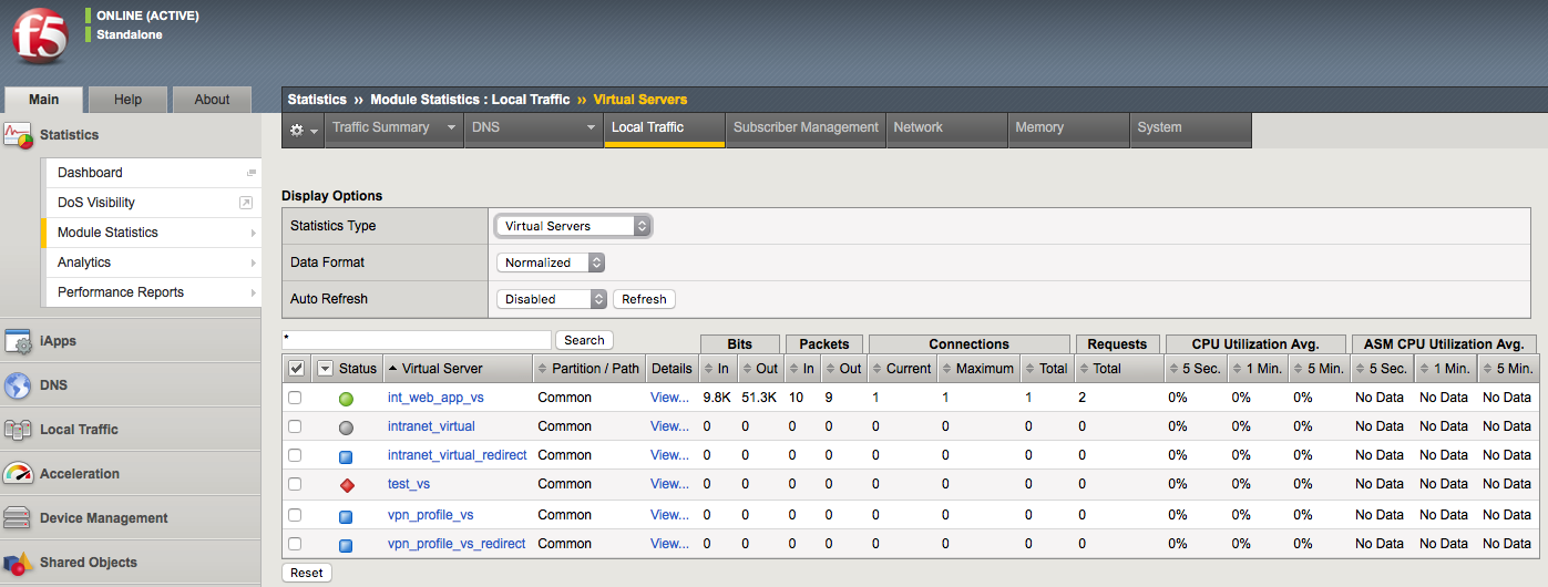
A vCMP configuration with a single-core guest
Because a single-core guest has a relatively small amount of CPU and memory allocated to it, F5 supports only these products or product combinations for a single-core guest:
- BIG-IP Local Traffic Manager (LTM) only
- BIG-IP Local Traffic Manager (LTM) and BIG-IP Global Traffic Manager (GTM) only
- BIG-IP Global Traffic Manager (GTM) standalone only
Resource allocation results
This illustration shows an example of a system with three guests that the vCMP host has distributed across slots in varying ways. The way that the host distributes the guests depends on the way you configured guest properties when you initially created each guest.
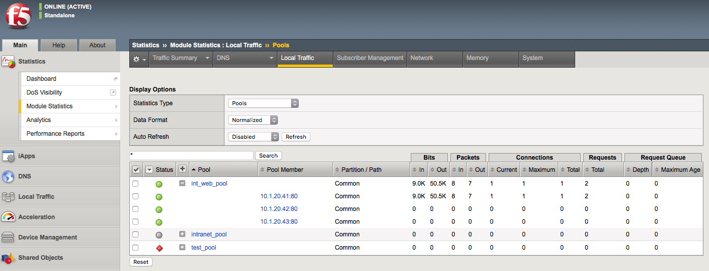
Three guests with varying amounts of core allocation and slot assignment
This illustration shows three guests configured on the system. For blade model B2100, which provides approximately 2 GB of memory per core:
- The blue guest is configured with two cores per slot, providing a total memory allocation of four GB per slot for the guest (2 cores x 2 GB). The guest spans four slots.
- The red guest is configured with two cores per slot, providing a total memory allocation of four GB per slot for the guest (2 cores x 2 GB). The guest spans two slots.
- The green guest is configured with four cores per slot, providing a total memory allocation of eight GB per slot for the guest (4 cores x 2 GB). The guest spans two slots.
Important: For an individual guest, the number of cores allocated to one (not all) of the guest’s slots determines the guest’s total memory allocation.
Scalability considerations
When managing a guest’s slot assignment, or when removing a blade from a slot assigned to a guest, there are a few key concepts to consider.
About initial slot assignment
When you create a vCMP guest, the number of slots that you initially allow the guest to run on determines the maximum total resource allocation possible for that guest, even if you add blades later. For example, in a four-slot VIPRION chassis that contains two blades, if you allow a guest to run on two slots only and you later add a third blade, the guest continues to run on two slots and does not automatically expand to acquire additional resource from the third blade. However, if you initially allow the guest to run on all slots in the cluster, the guest will initially run on the two existing blades but will expand to run on the third slot, acquiring additional traffic processing capacity, if you add another blade.
Because each connection causes some amount of memory use, the fewer the connections that the blade is processing, the lower the percentage of memory that is used on the blade compared to the total amount of memory allocated on that slot for the guest. Configuring each guest to span as many slots as possible reduces the chance that memory use will exceed the available memory on a blade when that blade must suddenly process additional connections.
If you do not follow the best practice of instructing the host to assign as many slots as possible for a guest, you should at least allow the guest to run on enough slots to account for an increase in load per blade if the number of blades is reduced for any reason.
In general, F5 strongly recommends that when you create a guest, you assign the maximum number of available slots to the guest to ensure that as few additional connections as possible are redistributed to each blade, therefore resulting in as little increase in memory use on each blade as possible.
About changing slot assignments
At any time, you can intentionally increase or decrease the number of slots a guest runs on explicitly by re-configuring the number of slots that you initially assigned to the guest. Note that you can do this while a guest is processing traffic, to either increase the guest’s resource allocation or to reclaim host resources.
When you increase the number of slots that a guest is assigned to, the host attempts to assign the guest to those additional slots. The host first chooses those slots with the greatest number of available cores. The change is accepted as long as the guest is still assigned to at least as many slots as dictated by its Minimum Number of Slotsvalue. If the additional number of slots specified is not currently available, the host waits until those additional slots become available and then assigns the guest to these slots until the guest is assigned to the desired total number of slots. If the guest is currently in a deployed state, VMs are automatically created on the additional slots.
When you decrease the number of slots that a guest is assigned to, the host removes the guest from the most populated slots until the guest is assigned to the correct number of slots. The guest’s VMs on the removed slots are deleted, although the virtual disks remain on those slots for reassignment later to another guest. Note that the number of slots that you assign to a guest can never be less than the minimum number of slots configured for that guest.
Effect of blade removal on a guest
If a blade suddenly becomes unavailable, the total traffic processing resource for guests on that blade is reduced and the host must redistribute the load on that slot to the remaining assigned slots. This increases the number of connections that each remaining blade must process.
Fortunately, there is no reduction in memory allocation, given that when you create a guest, you instruct the host to allocate the full amount of required memory for that guest to every slot in the guest’s cluster (through the guest’s Cores per Slot property). However, each connection causes some amount of memory use, which means that when a blade becomes unavailable and the host redistributes its connections to other blades, the percentage of memory use on these remaining blades increases. In some cases, the increased memory use could exceed the amount of memory allocated to each of those slots.
For example, if a guest spans three slots which process 1,000,000 connections combined, each slot is processing a third of the connections to the guest. If one of the blades becomes unavailable, reducing the guest’s cluster to two slots, then the two remaining blades must each process half of the guest’s connections (500,000), resulting in a memory use per slot that could be higher than what is allocated for that slot. Assigning as many slots as possible to each guest reduces this risk.
Effect of blade re-insertion on a guest
When you remove a blade from the chassis, the host remembers which guests were allocated to that slot. If you then re-insert a blade into that slot, the host automatically allocates cores from that blade to the guests that were previously assigned to that slot.
Whenever the host assigns guests to a newly-inserted blade, those guests that are below their Minimum Number of Slots threshold are given priority; that is, the host assigns those guests to the slot before guests that are already assigned to at least as many slots as their Minimum Number of Slots value. Note that this is the only time when a guest is allowed to be assigned to fewer slots than specified by its Minimum Number of Slots value.
About SSL and compression hardware
On systems that include SSL and compression hardware processors, the vCMP feature shares these hardware resources among all guests on the system, in a round robin fashion.
When sharing SSL hardware, if all guests are using similar-sized keys, then each guest receives an equal share of the SSL resource. Also, if any guests are not using SSL keys, then other guests can take advantage of the extra SSL resource.
Guest states and resource allocation
As a vCMP host administrator, you can control when the system allocates or de-allocates system resources to a guest. You can do this at any time, by setting a guest to one of three states: Configured, Provisioned, or Deployed. These states affect resource allocation in these ways:
Configured
This is the initial (and default) state for a newly-created guest. In this state, the guest is not running, and no resources are allocated. If you change a guest from another state to the Configured state, the vCMP host does not delete any virtual disks that were previously attached to that guest; instead, the guest’s virtual disks persist on the system. The host does, however, automatically de-allocate other resources such as CPU and memory. When the guest is in the Configured state, you cannot configure the BIG-IP modules that are licensed to run within the guest; instead, you must set the guest to the Deployed state to provision and configure the BIG-IP modules within the guest.
Provisioned
When you change a guest state from Configured to Provisioned, the vCMP host allocates system resources to the guest (CPU, memory, and any unallocated virtual disks). If the guest is new, the host creates new virtual disks for the guest and installs the selected ISO image on them. A guest does not run while in the Provisioned state. When you change a guest state from Deployed to Provisioned, the host shuts down the guest but retains its current resource allocation.
Deployed
When you change a guest to the Deployed state, the vCMP host activates the guest virtual machines (VMs), and the guest administrator can then provision and configure the BIG-IP modules within the guest. For a guest in this state, the vCMP host starts and maintains a VM on each slot for which the guest has resources allocated. If you are a host administrator and you reconfigure the properties of a guest after its initial deployment, the host immediately propagates the changes to all of the guest VMs and also propagates the list of allowed VLANs.
2.11 - Understand that the vCMP guest license is inherited from the host
BIG-IP license considerations for vCMP
The BIG-IP system license authorizes you to provision the vCMP feature and create guests with one or more BIG-IP system modules provisioned. Note the following considerations:
Each guest inherits the license of the vCMP host.
The host license must include all BIG-IP modules that are to be provisioned across all guest instances. Examples of BIG-IP modules are BIG-IP Local Traffic Manager and BIG-IP Global Traffic Manager.
The license allows you to deploy the maximum number of guests that the platform allows.
If the license includes the appliance mode feature, you cannot enable appliance mode for individual guests; when licensed, appliance mode applies to all guests and cannot be disabled.
You activate the BIG-IP system license when you initially set up the vCMP host.
2.11 - Describe how to deploy and/or upgrade vCMP guests and related dependency on host version
https://support.f5.com/csp/article/K14088
Upgrading software on a vCMP system
When you upgrade software on vCMP systems, keep the following information in mind:
- When you upgrade a vCMP host, the guests go offline.
- Upgrading the vCMP host does not upgrade individual guests.
- To avoid excessive disk and CPU usage, upgrade only one vCMP guest at a time.
- Each guest inherits the license of the vCMP host, and the host license includes all BIG-IP modules available for use with vCMP guest instances. If you need to reactivate the license, you reactivate it at the vCMP host only.
- While not required, F5 recommends that you configure your vCMP host to run the same BIG-IP version as the latest version used by any of its vCMP guests.
- F5 hardware platforms with multiple blades manage and share software image ISO files between blades automatically. Starting in 11.6.0, BIG-IP software images that are stored and managed on the vCMP host are also available for vCMP guests to install.
- Hosts and guests use unique UCS configuration files. For example, virtual servers configured within a BIG-IP guest are not contained in the UCS file created on the vCMP host.
For more information, refer to K15930: Overview of vCMP configuration considerations.
https://support.f5.com/csp/article/K14088
vCMP host and compatible guest version matrix
Starting in BIG-IP 11.0.0, the BIG-IP system supports vCMP, a feature that allows you to run multiple instances of the BIG-IP software on a single hardware platform. The hypervisor allows you to allocate hardware resources to each BIG-IP vCMP guest instance.
The vCMP host allows you to run a vCMP guest software version, which can be either the same version or a different version than the host, which is BIG-IP 11.0.0 and later. This functionality allows customers to run multiple versions of BIG-IP code simultaneously for testing, migration staging, or environment consolidation.
Objective - 2.12 Determine the appropriate LTM device security configuration to protect against a security threat
2.12 - Explain the implications of SNAT and NAT on network promiscuity
In a typical network, a host’s network adapter only receives frames that are meant for it. If the Host’s network adapter supports promiscuous mode, then placing it in promiscuous mode will allow it to receive all frames passed on the switch that are allowed under the VLAN policy for the associated port group. This can be useful for intrusion detection monitoring or if a sniffer needs to analyze all traffic on the network segment.
When the BIG-IP platform performs SNAT or NAT functions to the network traffic that is traversing the system it rewrites the destination IP or source IP address of the traffic depending on the function performed. This can make troubleshooting captures of network traffic difficult since with SNAT all traffic seems to have a source IP address of the BIG-IP system, or with NAT the destination IP address is not the same on each side of the communications of the BIG-IP.
2.12 - Explain the implications of forwarding virtual servers on the environment security
https://support.f5.com/csp/article/K7595?sr=42401954
Forwarding Virtual Servers
There are two different types of forwarding virtual server, the Layer2 forwarding and IP forwarding.
An IP forwarding virtual server accepts traffic that matches the virtual server address and forwards it to the destination IP address that is specified in the request rather than load balancing the traffic to a pool. Address translation is disabled when you create an IP forwarding virtual server, leaving the destination address in the packet unchanged. When creating an IP forwarding virtual server, as with all virtual servers, you can create either a host IP forwarding virtual server, which forwards traffic for a single host address, or a network IP forwarding virtual server, which forwards traffic for a subnet.
Host IP forwarding virtual server
A host IP forwarding virtual server forwards traffic to a single destination host address. For example, the following configuration defines a host IP forwarding virtual server that accepts any traffic arriving on the Virtual Local Area Network (VLAN) named external whose destination is 10.0.0.1 on any service port using any valid TCP/IP protocol. The traffic is forwarded from the external VLAN to the destination host at 10.0.0.1.
Network IP forwarding virtual server
A network IP forwarding virtual server forwards traffic to the destination network. For example, the following configuration example defines a network IP forwarding virtual server that accepts traffic from any VLAN bound for any host on the 10.0.0.0/24 network, but only if it arrives on TCP port 22. Matching traffic is forwarded from the originating VLAN to the host specified in the client request.
Note: IP forwarding virtual servers are similar to Layer 2 forwarding virtual servers in that neither one load balances traffic to pool members, but instead forward directly to the destination address requested by the client. For more information about Layer 2 forwarding virtual servers, refer to K8082: Overview of TCP connection setup for BIG-IP LTM virtual server types.
An IP forwarding virtual server is useful when you want to configure the BIG-IP system to pass infrastructure-related traffic, such as Internet Control Message Protocol (ICMP) traffic.
Emulating stateless IP routing with BIG-IP LTM forwarding virtual servers
The TMOS-based full-proxy model is stateful and connection-orientated by nature, in contrast to the stateless IP forwarding typically provided by L3 routers. The BIG-IP LTM system must be specifically configured to more closely emulate a standard router’s stateless routing behavior by adjusting the virtual server and protocol profile configurations to match your requirements.
For the closest approximation of stateless IP forwarding, F5 recommends that you create an IP forwarding wildcard virtual server. This configuration accepts traffic and forwards it using the information contained in the system routing table, regardless of whether it is associated with an established connection.
Note: The VLANs on which you enable the forwarding virtual server may vary depending on your routing requirements and restrictions. The virtual server should be enabled on all VLANs from which it will accept and route traffic.
The FastL4 profile determines how the system handles the connection table entries. Enabling the Loose Initiation option allows the system to initialize a connection when it receives any TCP packet, rather than requiring a SYN packet for connection initiation. It also provides a good alternative to the high overhead of connection mirroring. In the event of a failover, with the Loose Initiation option enabled, the standby BIG-IP system accepts connections mid-flow, and forwards, as expected. The Loose Close option allows the system to remove a connection when the system receives the first FIN packet from either the client or the server. This will help trim connection table entries as the connection entry can be removed as soon as the connection officially closes, and the system does not need to maintain the connection table entry.
Note: The Loose Close feature is optional, and may impact system performance because it disables Packet Velocity ASIC (PVA) Acceleration for the virtual server. For information about PVA Acceleration, refer to K4832: Overview of PVA Acceleration. The Loose Close feature does not impact ePVA acceleration. For information about ePVA acceleration, refer to K12837: Overview of the ePVA feature.
Setting the Idle Timeout allows the system to remove connections from the connection table when the connections are no longer active. F5 recommends that you use the default timeout of 300 seconds. If you disable Reset on Timeout, the system removes connection entries from the connection table once the idle timeout expires, but the system does not reset the connection. This setting prevents the BIG-IP LTM system from sending resets when closing an idle connection, it also reduces the need to use long idle timeouts for long-lived TCP connections, which may go idle for extended periods of time. For instance, if an application allows for long periods of inactivity (greater than the configured Idle Timeout) with no traffic being exchanged, then without this setting, the BIG-IP LTM system would close both sides of the connection when the timeout expired. The system would reject any subsequent packets that the client or server sent in the same TCP connection, since the connection is no longer valid on the BIG-IP LTM system. However, with Reset on Timeout disabled, the BIG-IP LTM quietly removes the connection entry and neither the client nor the server is aware that the communication channel has timed out. When the client or server begins communicating again, the Loose Initiation setting allows the BIG-IP LTM system to re-add the connection to the connection table, and the newly-arrived packets are forwarded, as expected.
Note: F5 does not recommend that you set the idle timeout for any virtual server to immediate or indefinite. Setting the timeout to immediate results in constant writing and deletion of connection entries for each datagram, creating undesirable overhead. Setting the timeout to indefinite (or to large values) results in a connection table that grows until all available memory is consumed, and typically results in an unplanned failover upon memory exhaustion.
Some protocols have different requirements than others. In which case, a more specific virtual server allows you to control traffic handling for specific protocols. A protocol-specific virtual server can help keep connection table sizes down, and if Last Hop is still used, will help reduce stale last hop information for short-lived connections. For instance, User Datagram Protocol (UDP) is less stateful than TCP, and does not typically require as long an idle timeout. To set a specific timeout for UDP traffic, you can create the wildcard forwarding virtual server described previously, and a protocol-specific forwarding virtual server and profile. This virtual server listens for only UDP traffic. All other IP protocols will be processed by the more general wildcard forwarding virtual server defined previously.
Forwarding Virtual Servers Security Concerns
Since the forwarding virtual server is not processing traffic to a specific pool resource traffic can be destined for any IP address in the subnet that the BIG-IP system is listening on. This may allow traffic to systems that you did not intend to pass.
2.12 - Explain how to set up and enable SNMP device traps on the LTM device
https://support.f5.com/csp/article/K3727
SNMP trap configuration files
Standard, pre-configured SNMP traps are contained in the /etc/alertd/alert.conf file. F5 does not recommend, or support, the addition or removal of traps or any other changes to the alert.conf file.
Custom, user-defined SNMP traps should be defined in the /config/user_alert.conf file.
The BIG-IP system will process the alert notification specified in the /config/user_alert.conf file first, if the same alert definition exists on both of the config files.
Prior to BIG-IP 10.1.0, when the alertd process starts, it creates a dynamic configuration file by appending the /config/user_alert.conf file to the /etc/alertd/alert.conf file. The BIG-IP system searches the dynamic configuration file sequentially for matches. After a match is found, the trap is generated and no further matches are attempted.
Note: All files in the /config directory, including any customizations to the /config/user_alert.conf file, are automatically included in the UCS archive by default. For more information, refer to K4422: Viewing and modifying the files that are configured for inclusion in a UCS archive.
Creating custom SNMP traps
Before you create a custom trap, you must determine the unique syslog messages for which you want the system to send alerts. The message must not match the matched_message value of any other SNMP trap already defined in the /etc/alertd/alert.conf file or the /config/user_alert.conf file.
Note: For information about how to determine which alerts are pre-configured to trigger an SNMP trap, refer to K6414: Determining which alerts are pre-configured to trigger an SNMP trap. You may also examine the alerts from the /config/user_alert.conf file in the same manner.
To create a custom SNMP trap, perform the following procedure:
- Log in to the command line.
2. To back up your /config/user_alert.conf file, type the following command:
cp /config/user_alert.conf /config/user_alert.conf.SOL3727
- Edit the /config/user_alert.conf file.
4. Add a new SNMP trap using the following format:
alert <alert_name> "<matched message>" {

snmptrap OID=".1.3.6.1.4.1.3375.2.4.0.XXX"

}
Note: Replace <alert_name> with a descriptive name. Do not use an alert name that exactly matches one already used in the /etc/alertd/alert.conf file or the /config/user_alert.conf file. Replace <matched_message> with text that matches the syslog message that triggers the custom trap. You can specify a portion of the syslog message text or use a regular expression. F5 recommends that you do not include the syslog prefix information, such as the date stamp and process ID, in the match string. Including information of a variable nature in the match string or regular expression may result in unexpected false positives or result in no matches at all. The syslog message you want to trap must not match the matched_message value of any other SNMP trap defined in the /etc/alertd/alert.conf file or the /config/user_alert.conf file.
- Replace XXX with a number unique to this object ID.
You can use any object ID that meets all of the following criteria:
- The object ID is in standard object identifier (OID) format, and within the following range:
.1.3.6.1.4.1.3375.2.4.0.300 through .1.3.6.1.4.1.3375.2.4.0.999
Note: If the OID value is outside the range listed above, a trap will be sent with the OID specified, but it will not contain any text within the trap body.
- The object ID is in a numeric range that can be processed by your trap receiving tool.
- The object ID does not already exist in the /usr/share/snmp/mibs/F5-BIGIP-COMMON-MIB.txt management information base (MIB) file.
- The object ID is not already used in another custom trap.
- Save the file and exit the editor.
Note: If the alertd process fails to start, examine the newly added entry to ensure it contains all of the required elements and punctuation.
Note: To test the newly created trap, refer to K11127: Testing SNMP traps on the BIG-IP system (9.4.x - 13.x).
Custom SNMP trap example
A message that appears similar to the following example is logged to the /var/log/ltm file when switchboard failsafe is enabled:
Sep 23 11:51:40 bigip1.askf5.com lacpd[27753]: 01160016:6:
Switchboard Failsafe enabled
To create a custom SNMP trap that is triggered whenever switchboard failsafe status changes are logged, add the following trap definition to the /config/user_alert.conf file:
alert SWITCHBOARD_FAILSAFE_STATUS "Switchboard Failsafe (.\*)" {

snmptrap OID=".1.3.6.1.4.1.3375.2.4.0.500"

}
2.12 - Describe the implications of port lockdown settings
https://support.f5.com/kb/en-us/products/big-ip_ltm/manuals/product/tmos-concepts-11-5-0/13.html
Port lockdown
Each self IP address has a feature known as port lockdown. Port lockdown is a security feature that allows you to specify particular UDP and TCP protocols and services from which the self IP address can accept traffic.
You can determine the supported protocols and services by using the tmsh command tmsh list net self-allow defaults.
If you do not want to use the default setting (Allow None), you can configure port lockdown to allow either all UDP and TCP protocols and services (Allow All) or only those that you specify (Allow Custom).
Note: High availability-related traffic from configured peer devices in a device group might not be subject to port lockdown settings.
https://support.f5.com/csp/article/K13250
The port lockdown feature allows you to secure the BIG-IP system from unwanted connection attempts by controlling the level of access to each self IP address defined on the system. Each port lockdown list setting, defined later in this document, specifies the protocols and services from which a self IP can accept connections. The system refuses traffic and connections made to a service or protocol port that is not on the list.
Port lockdown exceptions
- TCP port 1028: In BIG-IP 11.0.0 - 11.3.0 redundant pair configurations, the system allows tcp:1028 for connection and persistence mirroring, regardless of the port lockdown settings.
- TCP port 1029 - 1043: Beginning in BIG-IP 11.4.0, the BIG-IP system maintains a separate mirroring channel for each traffic group. The port range for each connection channel begins at TCP 1029 and increments by one for each new traffic group and channel created. By default, the BIG-IP system allows TCP ports 1029-1043. For more information, refer to K14894: The BIG-IP system establishes a separate mirroring channel for each traffic group.
- TCP port 4353: When BIG-IP 11.0.0 and later devices are configured in a synchronization group, peer devices communicate using Centralized Management Infrastructure (CMI) on tcp:4353, regardless of the port lockdown settings.
Note: CMI uses the same port as iQuery tcp:4353, but is independent of iQuery and the port configuration options available for the port. If you are using iQuery, you must allow port 4353 in your port lockdown settings.
- ICMP: ICMP traffic to the self-IP address is not affected by the port lockdown list and is implicitly allowed in all cases.
Note: In most cases, it is not possible to ping self IP addresses across Virtual Local Area Networks (VLANs). For more information, refer to K3475: The BIG-IP system may not respond to requests for a self IP address.
Port lockdown setting definitions:
Allow Default
This option allows access to a pre-defined set of network protocols and services that are typically required in a BIG-IP deployment.
The Allow Default setting specifies that connections to the self IP address are allowed from the following protocols and services:
Allowed protocol Service Service definition
| Allowed protocol | Service | Service definition |
|---|---|---|
| OSPF | N/A | N/A |
| TCP | 4353 | iQuery |
| UDP | 4353 | iQuery |
| TCP | 443 | HTTPS |
| TCP | 161 | SNMP |
| UDP | 161 | SNMP |
| TCP | 22 | SSH |
| TCP | 53 | DNS |
| UDP | 53 | DNS |
| UDP | 520 | RIP |
| UDP | 1026 | network failover |
You can also determine the default supported protocols and services by using the following command:
tmsh list net self-allow
The output appears similar to the following example:
net self-allow {
defaults {
ospf:any
tcp:domain
tcp:f5-iquery
tcp:https
tcp:snmp
tcp:ssh
udp:520
udp:cap
udp:domain
udp:f5-iquery
udp:snmp
}
}
- Allow All
This option specifies that all connections to the self IP address are allowed, regardless of protocol or service.
- Allow None
This option specifies that no connections are allowed on the self IP address, regardless of protocol or service. However, ICMP traffic is always allowed, and if the BIG-IP systems are configured in a redundant pair, ports that are listed as exceptions are always allowed from the peer system.
- Allow Custom
This option allows you to specify the protocols and services for which connections are allowed on the self IP address. However, ICMP traffic is always allowed, and if the BIG-IP systems are configured in a redundant pair, ports that are listed as exceptions are always allowed from the peer system.
Important: A known issue prevents connections to the state mirroring address when port tcp:1028 is explicitly allowed in the custom port lockdown list. For more information, refer to K12932: The BIG-IP system resets statemirror connections when port 1028 is configured in the Self IP Port Lockdown list.
Default port lockdown setting
When creating self IP addresses using the Configuration utility, the default port lockdown setting in BIG-IP 10.x through 11.5.2 is Allow Default, and for BIG-IP 11.6.0 and later versions is Allow None.
When creating self IP addresses using the bigpipe or tmsh utilities, the default port lockdown setting in BIG-IP 10.x is Allow None. For BIG-IP 11.0.0 - 11.5.2, the default port lockdown setting is Allow Default, and for BIG-IP 11.5.3 and 11.6.0 and later versions, the default port lockdown setting is Allow None.
Using the Configuration utility to modify port lockdown settings for a specific self IP
- Log in to the Configuration utility.
- Navigate to Network > Self IPs.
- Click the relevant self IP address.
- From the Port Lockdown box, click the setting you want.
- Click Update.
Using the tmsh utility to modify port lockdown settings
1. Log in to the Traffic Management Shell (tmsh) by typing the following command:
tmsh
2. To modify the port lockdown settings for a self IP address, use the following command syntax:
modify /net self <self_IP> allow-service <option>
For example, to change the port lockdown setting for self IP address 10.10.10.1 to default, you would type the following command:
modify /net self 10.10.10.1 allow-service default
- Save the change by typing the following command:
BIG-IP 10.1.0 and later:
save sys config
Recommendations
For optimal security, F5 recommends that you use the port lockdown feature to allow only the protocols or services required for a self IP address.
2.12 - (Supplemental Example) Describe how to disable services
Making the BIG-IP Listen for a service
The Big-IP platform is a default deny network platform. You have to configure the BIG-IP to listen for traffic whether that is for management or for production traffic. Virtual servers are the listeners for application traffic services. Some listeners need to be built to pass more than one type of traffic. And many times, the configuration will allow either one port or all ports. If you want to restrict it to a short list of ports, an iRule can be used that will allow the selective list of ports.
Simply sending a TCP reset to a port scan can tell an intruder a lot about your environment. By default, the TM.RejectUnmatched BigDB variable is set to true, and the BIG-IP system sends a TCP RST packet in response to a non-SYN packet that matches a virtual server address and port or self IP address and port, but does not match an established connection. The BIG-IP system also sends a TCP RST packet in response to a packet that matches a virtual server address, or self IP address, but specifies an invalid port. The TCP RST packet is sent on the client side of the connection, and the source IP address of the reset is the relevant BIG-IP LTM object address or self IP address for which the packet was destined. If TM.RejectUnmatched is set to false, the system silently drops unmatched packets.
2.12 - (Supplemental Example) Describe how to disable ARP
Address Resolution Protocol on the BIG-IP system
The BIG-IP system is a multi-layer network device, and as such, needs to perform routing functions. To do this, the BIG-IP system must be able to find destination MAC addresses on the network, based on known IP addresses. The way that the BIG-IP system does this is by supporting Address Resolution Protocol (ARP), an industry-standard Layer 3 protocol. Settings for ARP behaviors can be found on the Main tab, click Network > ARP > Options. You can also see and manage the dynamic and static ARP entries in ARP cache from the console or the GUI.
Disabling ARP for A Virtual Server’s Address
If you want to control how the BIG-IP handles ARP for a virtual server you can make a change to the configuration of the virtual address of the virtual server.
What is a virtual address?
A virtual address is the IP address with which you associate a virtual server. For example, if a virtual server’s IP address and service are 10.10.10.2:80, then the IP address 10.10.10.2 is a virtual address.
You can create a many-to-one relationship between virtual servers and a virtual address. For example, you can create the three virtual servers 10.10.10.2:80, 10.10.10.2:443, and 10.10.10.2:161 for the same virtual address, 10.10.10.2.
You can enable and disable a virtual address. When you disable a virtual address, none of the virtual servers associated with that address can receive incoming network traffic.
You create a virtual address indirectly when you create a virtual server. When this happens, Local Traffic Manager internally associates the virtual address with a MAC address. This in turn causes the BIG-IP system to respond to Address Resolution Protocol (ARP) requests for the virtual address, and to send gratuitous ARP requests and responses with respect to the virtual address. As an option, you can disable ARP activity for virtual addresses, in the rare case that ARP activity affects system performance. This most likely occurs only when you have a large number of virtual addresses defined on the system.
2.12 - (Supplemental Example) Explain how to set up logging for security events on the LTM device
Overview: Configuring DoS Protection event logging
You can configure the BIG-IP system to log information about BIG-IP system denial-of-service (DoS) events, and send the log messages to remote high-speed log servers.
Important: The BIG-IP Advanced Firewall Manager (AFM) must be licensed and provisioned before you can configure DoS Protection event logging. Additionally, for high-volume logging requirements, such as DoS, ensure that the BIG-IP system sends the event logs to a remote log server.
When configuring remote high-speed logging of DoS Protection event logging, it is helpful to understand the objects you need to create and why, as described here:
| Object to create in implementation | Reason |
|---|---|
| Pool of remote log servers | Create a pool of remote log servers to which the BIG-IP system can send log messages. |
| Destination (unformatted) | Create a log destination of Remote High-Speed Log type that specifies a pool of remote log servers. |
| Destination (formatted) | If your remote log servers are the ArcSight, Splunk, IPFIX, or Remote Syslog type, create an additional log destination to format the logs in the required format and forward the logs to a remote high-speed log destination. |
| Publisher | Create a log publisher to send logs to a set of specified log destinations. |
| Logging profile | Create a custom Logging profile to enable logging of user-specified data at a user-specified level, and associate a log publisher with the profile. |
| LTM virtual server | Associate a custom Logging profile with a virtual server to define how the BIG-IP system logs security events on the traffic that the virtual server processes. |
This illustration shows the association of the configuration objects for remote high-speed logging of DoS Protection events.

Association of remote high-speed logging configuration objects
Task summary
Perform these tasks to configure logging of DoS Protection events on the BIG-IP system.
Note: Enabling logging impacts BIG-IP system performance.
Creating a pool of remote logging servers
Before creating a pool of log servers, gather the IP addresses of the servers that you want to include in the pool. Ensure that the remote log servers are configured to listen to and receive log messages from the BIG-IP system.
Create a pool of remote log servers to which the BIG-IP system can send log messages.
- On the Main tab, click DNS > Delivery > Load Balancing > Pools or Local Traffic > Pools. The Pool List screen opens.
- Click Create. The New Pool screen opens.
- In the Name field, type a unique name for the pool.
- Using the New Members setting, add the IP address for each remote logging server that you want to include in the pool:
- Type an IP address in the Address field, or select a node address from the Node List.
- Type a service number in the Service Port field, or select a service name from the list. Note: Typical remote logging servers require port 514.
- Click Add.
- Click Finished.
Creating a remote high-speed log destination
Before creating a remote high-speed log destination, ensure that at least one pool of remote log servers exists on the BIG-IP system. Create a log destination of the Remote High-Speed Log type to specify that log messages are sent to a pool of remote log servers.
- On the Main tab, click System > Logs > Configuration > Log Destinations. The Log Destinations screen opens.
- Click Create.
- In the Name field, type a unique, identifiable name for this destination.
- From the Type list, select Remote High-Speed Log.
Important: If you use log servers such as Remote Syslog, Splunk, or ArcSight, which require data be sent to the servers in a specific format, you must create an additional log destination of the required type, and associate it with a log destination of the Remote High-Speed Log type. With this configuration, the BIG-IP system can send data to the servers in the required format. The BIG-IP system is configured to send an unformatted string of text to the log servers.
- From the Pool Name list, select the pool of remote log servers to which you want the BIG-IP system to send log messages.
- From the Protocol list, select the protocol used by the high-speed logging pool members.
- Click Finished.
Creating a formatted remote high-speed log destination
Ensure that at least one remote high-speed log destination exists on the BIG-IP system.
Create a formatted logging destination to specify that log messages are sent to a pool of remote log servers, such as Remote Syslog, Splunk, or ArcSight servers.
- On the Main tab, click System > Logs > Configuration > Log Destinations. The Log Destinations screen opens.
- Click Create.
- In the Name field, type a unique, identifiable name for this destination.
- From the Type list, select a formatted logging destination, such as IPFIX, Remote Syslog, Splunk, or ArcSight.
Important: ArcSight formatting is only available for logs coming from Advanced Firewall Manager (AFM), Application Security Manager (ASM), and the Secure Web Gateway component of Access Policy Manager (APM). IPFIX is not available for Secure Web Gateway. The BIG-IP system is configured to send a formatted string of text to the log servers.
- If you selected Remote Syslog, from the Syslog Format list, select a format for the logs, and then from the High-Speed Log Destination list, select the destination that points to a pool of remote Syslog servers to which you want the BIG-IP system to send log messages.
- If you selected Splunk or IPFIX, from the Forward To list, select the destination that points to a pool of high-speed log servers to which you want the BIG-IP system to send log messages.
- Click Finished.
Creating a publisher
Ensure that at least one destination associated with a pool of remote log servers exists on the BIG-IP system. Create a publisher to specify where the BIG-IP system sends log messages for specific resources.
- On the Main tab, click System > Logs > Configuration > Log Publishers. The Log Publishers screen opens.
- Click Create.
- In the Name field, type a unique, identifiable name for this publisher.
- For the Destinations setting, select a destination from the Available list, and click << to move the destination to the Selected list.
Note: If you are using a formatted destination, select the destination that matches your log servers, such as Remote Syslog, Splunk, or ArcSight.
- Click Finished.
Creating a custom DoS Protection Logging profile
Create a custom Logging profile to log DoS Protection events and send the log messages to a specific location.
- On the Main tab, click Security > Event Logs > Logging Profiles. The Logging Profiles list screen opens.
- Click Create. The New Logging Profile screen opens.
- Select the DoS Protection check box.
- In the DNS DoS Protection area, from the Publisher list, select the publisher that the BIG-IP system uses to log DNS DoS events. You can specify publishers for other DoS types in the same profile, for example, for SIP or Application DoS Protection.
- Click Finished.
Assign this custom DoS Protection Logging profile to a virtual server.
Configuring an LTM virtual server for DoS Protection event logging
Ensure that at least one Log Publisher exists on the BIG-IP system.
Assign a custom DoS Protection Logging profile to a virtual server when you want the BIG-IP system to log DoS Protection events on the traffic the virtual server processes.
Note: This task applies only to LTM-provisioned systems.
- On the Main tab, click Local Traffic > Virtual Servers. The Virtual Server List screen opens.
- Click the name of the virtual server you want to modify.
- On the menu bar, click Security > Policies. The screen displays Policy settings and Inline Rules settings.
- From the Log Profile list, select Enabled. Then, for the Profile setting, move the profiles that log specific events to specific locations from the Available list to the Selected list.
- Click Update to save the changes.
Disabling logging
Disable Network Firewall, Protocol Security, or DoS Protection event logging when you no longer want the BIG-IP system to log specific events on the traffic handled by specific resources.
Note: You can disable and re-enable logging for a specific resource based on your network administration needs.
- On the Main tab, click Local Traffic > Virtual Servers. The Virtual Server List screen opens.
- Click the name of the virtual server you want to modify.
- On the menu bar, click Security > Policies. The screen displays Policy settings and Inline Rules settings.
- From the Log Profile list, select Disabled.
- Click Update to save the changes.
The BIG-IP system does not log the events specified in this profile for the resources to which this profile is assigned.
Implementation result
You now have an implementation in which the BIG-IP system logs specific DoS Protection events and sends the logs to a specific location.
2.12 - (Supplemental Example) Explain how route domains can be used to enforce network segmentation
What is a route domain?
A route domain is a configuration object that isolates network traffic for a particular application on the network.
Because route domains segment network traffic, you can assign the same IP address or subnet to multiple nodes on a network, provided that each instance of the IP address resides in a separate routing domain.
Note: Route domains are compatible with both IPv4 and IPv6 address formats.
Benefits of route domains
Using the route domains feature of the BIG-IP system, you can provide hosting service for multiple customers by isolating each type of application traffic within a defined address space on the network.
With route domains, you can also use duplicate IP addresses on the network, provided that each of the duplicate addresses resides in a separate route domain and is isolated on the network through a separate VLAN. For example, if you are processing traffic for two different customers, you can create two separate route domains. The same node address (such as 10.0.10.1) can reside in each route domain, in the same pool or in different pools, and you can assign a different monitor to each of the two corresponding pool members.
Sample partitions with route domain objects
This illustration shows two route domain objects on a BIG-IP system, where each route domain corresponds to a separate customer, and thus resides in its own partition. Within each partition, the customer created the network objects and local traffic objects required for that customer’s application (AppA or AppB).
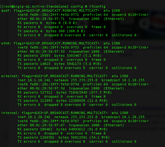
Sample route domain deployment
A good example of the use of route domains is a configuration for an ISP that services multiple customers, where each customer deploys a different application. In this case, the BIG-IP system isolates traffic for two different applications into two separate route domains. The routes for each application’s traffic cannot cross route domain boundaries because cross-routing restrictions are enabled on the BIG-IP system by default.
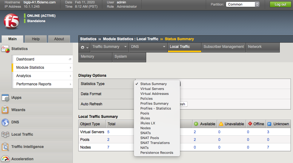
About strict isolation
You can control the forwarding of traffic across route domain boundaries by configuring the strict isolation feature of a route domain:
If strict isolation is enabled, the BIG-IP system allows traffic forwarding from that route domain to the specified parent route domain only. This is the default behavior. Note that for successful isolation, you must enable the strict isolation feature on both the child and the parent route domains.
If strict isolation is disabled, the BIG-IP system allows traffic forwarding from that route domain to any route domain on the system, without the need to define a parent-child relationship between route domains. Note that in this case, for successful forwarding, you must disable the strict isolation feature on both the forwarding route domain and the target route domain (that is, the route domain to which the traffic is being forwarded).
Conclusion
This document is intended as a study guide for the F5 301a – LTM Specialist: Architect, Set-Up & Deploy exam version 2 - TMOS v11.5.0. This study guide is not an all-inclusive document that will guarantee a passing grade on the exam. It is intended to be a living doc and any feedback or material that you feel should be included, to help exam takers better prepare, can be sent to F5CertGuides@f5.com.
Thank you for using this study guide to prepare the 301a – LTM Specialist exam and good luck with your certification goals.