Deployment maintenance guide
Consult the following topics, which provide further discussion and how-to information for performing the previous setup and deployment maintenance steps.
Blueprints
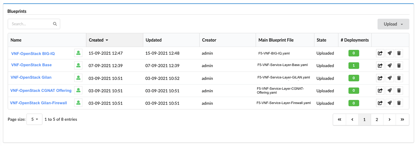
In the left-side pane, click Blueprints blade to display a list of all blueprints and details:
- Blueprint name
- Visibility level - click the
 icon next to the name, to permit users
(the sites’s creator, sys admins, or tenant managers of the current tenant) to set the visibility as a private/visible/global resource.
icon next to the name, to permit users
(the sites’s creator, sys admins, or tenant managers of the current tenant) to set the visibility as a private/visible/global resource. - Created date
- Updated date (last updated date)
- Creator (user name) who uploaded/composed the blueprint
- Main Blueprint File name and file type (for example, .yaml)
- # Deployments derived from the associated blueprint
- Upload
 action to add another (identical) blueprint
 - Deploy
 action to deploy selected blueprint
 - Delete
 blueprint to remove selected blueprint from the VNF Manager
To manage and deploy blueprints
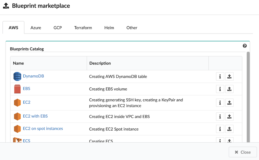
Click Upload to add a new blueprint:
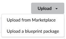
From the marketplace (click a public cloud provider or opensource infrastructure tab to view available options)
From a local directory or server (providing a URL, blueprint name, yaml file name, and optional icon.png file)
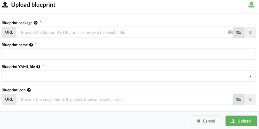
Blueprint name is the name with which you want to identify this blueprint once uploaded. Blueprint YAML file is the name of the YAML file in the archive that you want to upload as the main blueprint - as multiple files can exist in the archive. If you omit a blueprint filename, the default blueprint.yaml filename is used (if filename is not already used). If blueprint.yaml filename exist in the archive, you receive an error message.
To deploy a blueprint, click the
, in the Deploy Blueprint dialog, complete the following information,
and then click Deploy or Deploy & Install:Name for your deployment
Required deployment inputs - names of the default input values appear in the inputs fields. You can leave these defaults or override them with new values. Hover your mouse over the input Help icon to view input descriptions. You can also upload an inputs .yaml file containing the required input values.
Under Deployment metadata, expand Site name, and choose an existing site to which this deployment will be assigned and expand Labels, and select an existing label (key-value pair) that you want assigned to this deployment.
Under Execution parameters, ONLY toggle ON Skip plugins validation setting when developing plugins; otherwise set to OFF, and toggle ON Runtime only evaluation if you want
get_propertyandget_inputintrinsic functions evaluated on demand at runtime. Set to OFF and these evaluations occur ONLY when the deployment is created.Click
to define user permissions for this blueprint.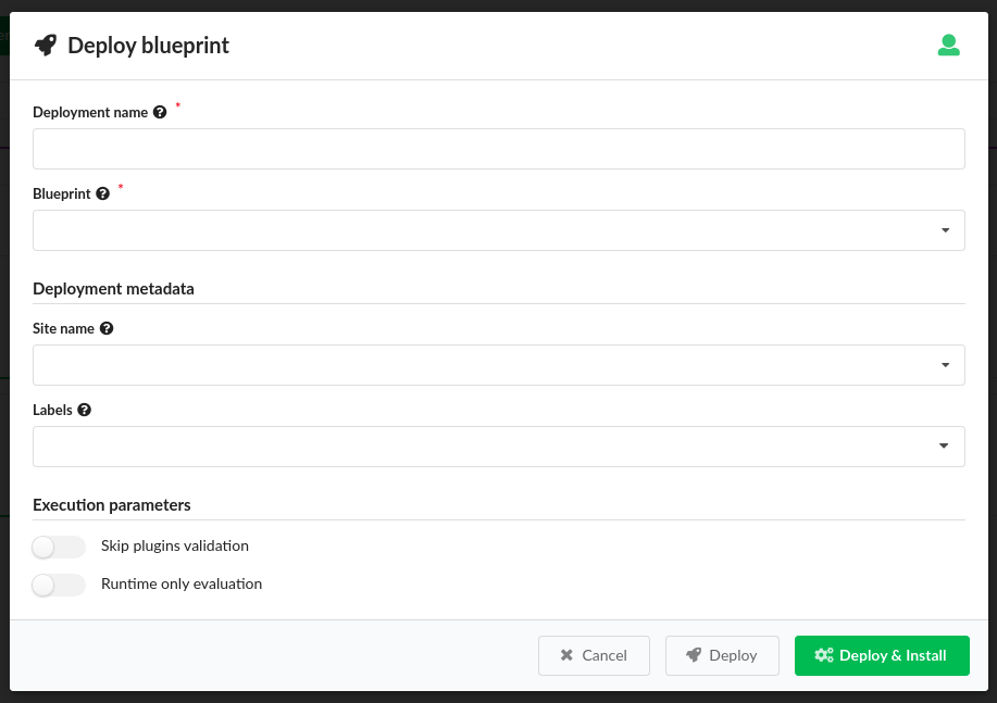
The blueprint deploys and install workflow executes (if selected).
Click a blueprint name in the table to view blueprint details.
Settings
- Refresh time interval - The time interval in which the widget’s data will be refreshed, in seconds. Default: 10 seconds
- Enable click to drill down - This option enables redirecting to the blueprint’s drill-down page upon clicking on a specific blueprint. Default: Yes
- Display style - Defines how the blueprints list should be displayed. Can be either Catalog or Table. Default: Table
- Show Composer options - This option allows to show VNFM Composer options in menu and in the blueprints list. Default: No
- Marketplace tabs - Allows to define multiple sources from which blueprints are taken to populate Blueprint Marketplace modal. User can define a name and URL for each tab.
- Marketplace display style - Defines how the Blueprints Marketplace modal should be displayed. Can be either Catalog or Table. Default: Table
- List of fields to show in the marketplace table - Allow to change the list of visible columns in the Blueprint Marketplace modal. Works only when Marketplace display style is set to Table. Default: Name, Description.
Deployment Services (blueprint deployment details)
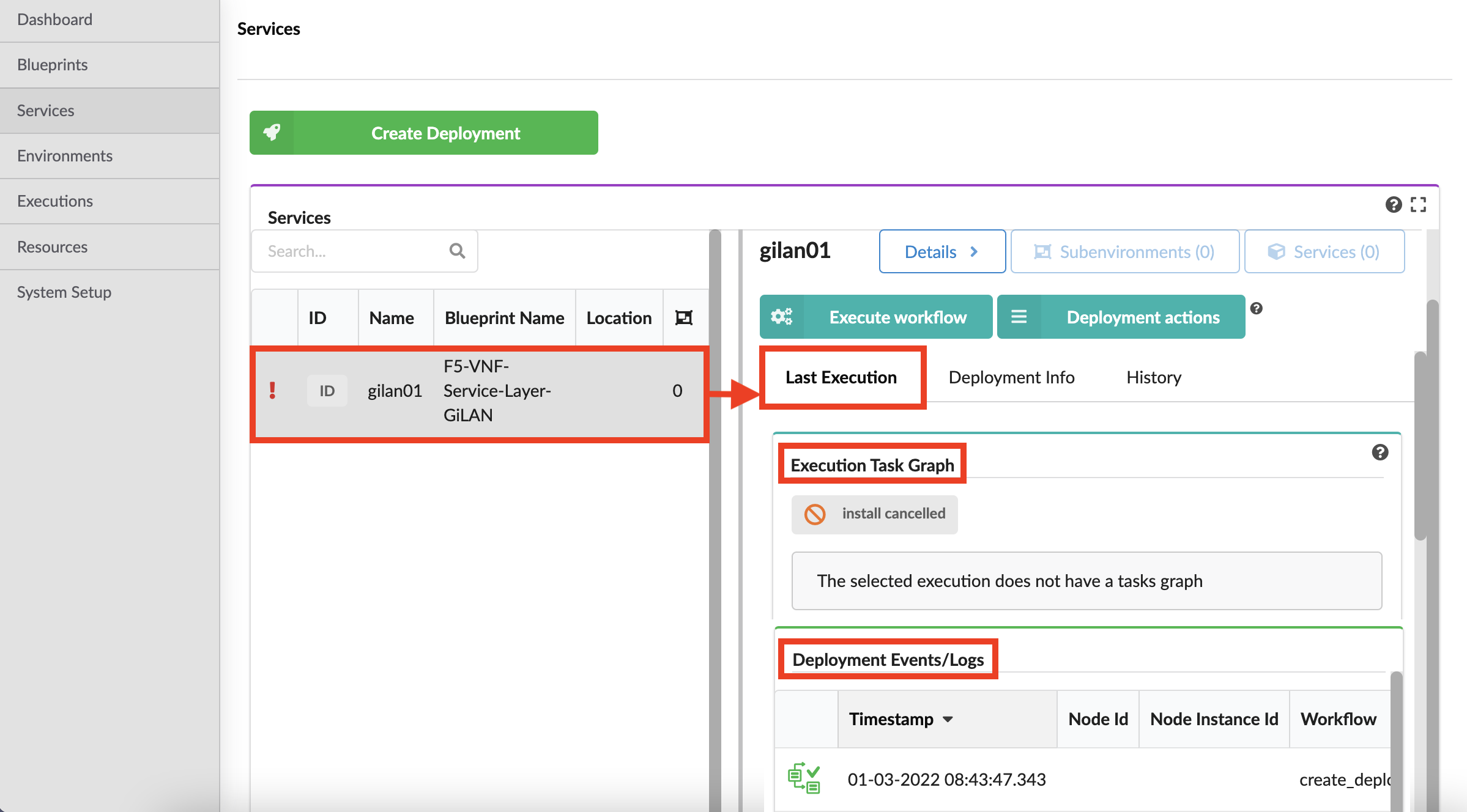
In the left side menu, click the Deployment blade, and then click the Services option to view a table listing all currently deployed blueprints and a deployment details pane:
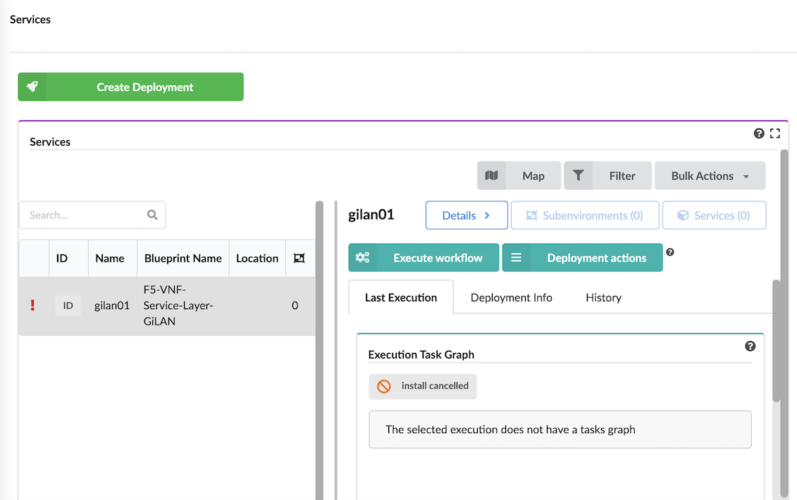
The Services table:
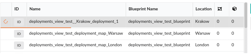
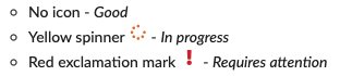
Deployment status icons:
Deployment ID
Deployment display name
Blueprint name from which the deployment is derived
Location the name of the site to which the deployment is assigned
Environment Type - the value of the
csys-env-typelabel for that deploymentThe counts and statuses of child deployments depending on their type (environments or services)
In the right-side of Services pane, use the following actions:
Map to toggle viewing of deployment locations on a resizable map.
Filter to refine the list of deployments and to create filters using rules based on Labels, Blueprint names, Site name, and Creator (user) name.
Bulk Actions that includes enabling you to perform the following actions over all deployments that match the defined filter criteria:
- Deploy On - additional services on the environments matching the defined filter. After selecting the base blueprint
for the new deployments, providing a name suffix to append to each deployment name, and additional labels (key-value pairs)
assigned with the deployment, a new child deployment is created for each deployment
matching the defined filter. Each generated deployment is labeled with the Environment ID of the environment on which
it is deployed as a parent label, and you can retrieve the capabilities of that parent environment using the
get-environment-capabilityintrinsic function. The newly created child deployments will be automatically installed. - Run Workflow - to select a workflow that you want to execute on each deployment matching the defined filter.
- Deploy On - additional services on the environments matching the defined filter. After selecting the base blueprint
for the new deployments, providing a name suffix to append to each deployment name, and additional labels (key-value pairs)
assigned with the deployment, a new child deployment is created for each deployment
matching the defined filter. Each generated deployment is labeled with the Environment ID of the environment on which
it is deployed as a parent label, and you can retrieve the capabilities of that parent environment using the
Details button displays all deployment details in an expanded window that includes information on the following tabs.
 Execute workflow button displays all blueprint workflows you can run for the current selection:
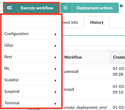
Expand the workflow options (for example, Gilan), to view workflows you can run for that specific blueprint deployment. Once you Execute workflow (see how to here) and provide parameter values, you can track the progress of the execution at the bottom of the deployment row, there will be thin line visible. Progress is calculated based on number of node instances installed (for example, the install workflow) or deleted (for example, the uninstall workflow).

The color of the line indicates the status of the execution:
- Green - succeeded
- Yellow - in progress
- Red - failed
Each of the workflows are described in detail here.
Use the following CLI commands to manage/execute workflows:
Start/Execute
vnfm executions start <WORKFLOW_NAME> -d <DEPLOYMENT_NAME>
Test install
vnfm deployments outputs <DEPLOYMENT_NAME>
Uninstall
vnfm executions start uninstall -d <DEPLOYMENT_NAME>Similarly to the install workflow, you can track the progress of the uninstall process in the CLI or the VNF Management Console. After the workflow is complete, verify that the resources deleted successfully.
Delete deployment
vnfm deployments delete <DEPLOYMENT_NAME>deletion options include:-v, --verbose- Show verbose output. You can supply this up to three times, for example-vvv.-t, --tenant-name- Specify the tenant where the blueprint in stored. (Default: current tenant)-f, --force flag- Delete the deployment even it contains active nodes.Deleting a deployment enables you to clean the environment of excess artifacts that continue to consume resources like, static and runtime properties from the database, and deployment-specific agents.
Settings
Refresh time interval- The time interval in which the widget’s data will be refreshed, in seconds. Default interval is 10 seconds.Enable click to drill down- This option enables redirecting to the deployment’s drill down page upon clicking on a specific deployments. Default setting is On.Show execution status label- Enables showing last execution workflow ID and status near last execution status icon. Default setting is Off.Blueprint ID to filter by- Enables filtering the deployments in this list to those derived from a specific blueprint, by providing its ID (the blueprint ID is its name). Default value is empty.Display style- Can be either list (default) or table. The deployments status column is only available in list mode.
 Deployment actions button displays all the deployment actions you can run on the current selection:
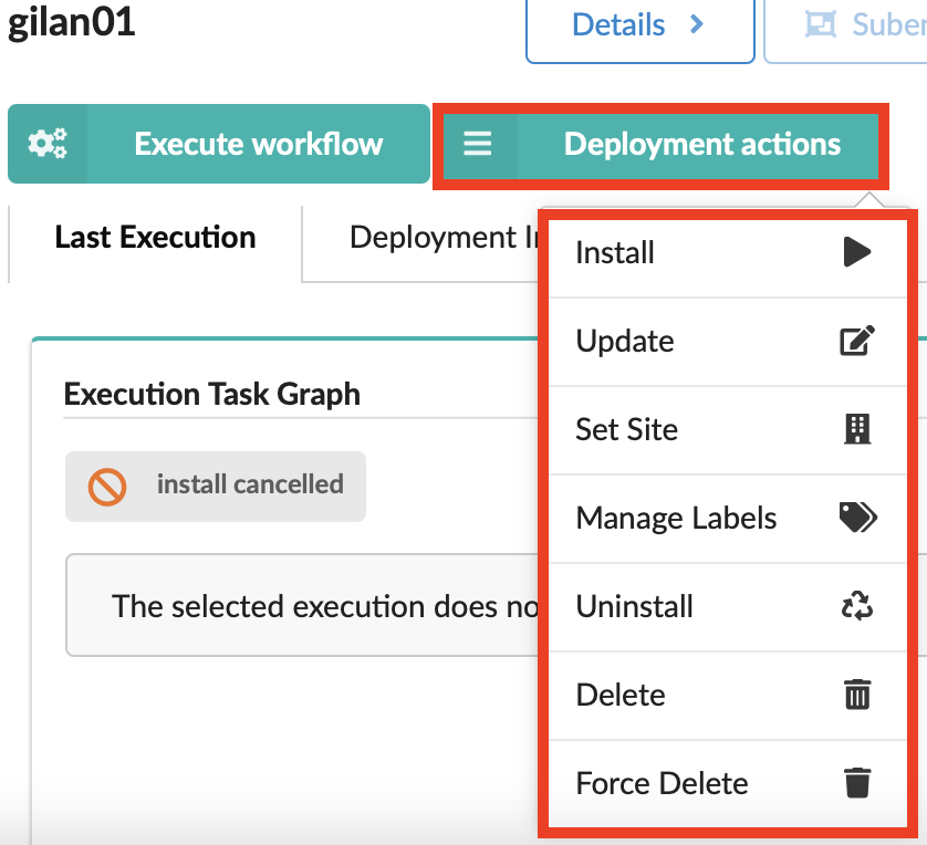
- Install
- Uninstall deployment
- Update deployment
- Set site for deployment
- Delete or Force Delete deployment
The right-side Services pane also displays the following tabs for the selected deployment:
- Last Execution displaying an Execution Task Graph
- Deployment Info displaying a Deployment Topology graph and other details
- History displaying Deployment Executions and Deployment Events and Logs
Last Execution
Use the Last Execution tab to view the Execution Task Graph and check status and deployment events and logs of the last workflow executed on the deployment:
The last execution status indicators include the following:
| Icon | Status description |
|---|---|
| Blueprint deployment execution failed. | |
| Blueprint deployment execution in progress. | |
| Blueprint deployment execution was canceled. | |
| Blueprint deployment execution is either scheduled or queued, and it is waiting. | |
| Blueprint deployment execution compelted successfully. |
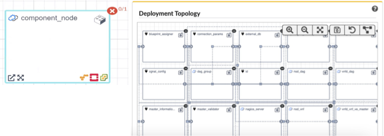
Deployment Info
The Deployment Info tabs provides the following panes (widgets):
Deployment Topology - of the selected blueprint or the selected deployment. Each blueprint node (name + icon) is displayed as a square container that can contain other nodes. Icons represent the node type relationships, status, and plugin type used. Arrows start at the connected node and end at the target node.
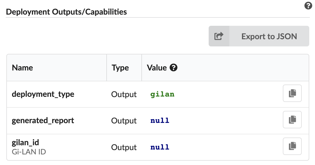
Deployment Outputs/Capabilities - lists names and values of the outputs and capabilities of the selected deployment. If you select a blueprint, this pane displays default values for the outputs, defined in the blueprint itself.
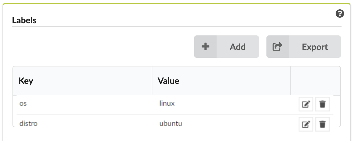
Labels - list of key-value labels defined for the selected deployment/blueprint.
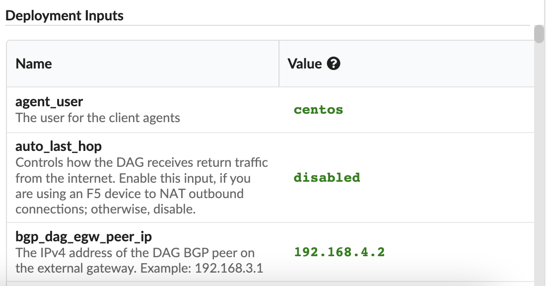
Deployment Inputs - names and values of the inputs for the selected deployment, or input default values for the selected blueprint.
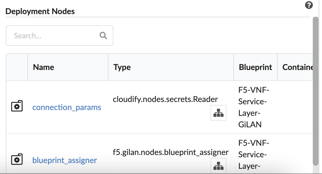
Deployment Nodes - lists existing nodes in the current tenant, according to your user-permissions. This pane displays the node’s blueprint and deployment, type, connected nodes, number of instances, and nodes groups of which the node is part. Click the Name to display more information.
The status of the deployments’ node instances indicators include the following:
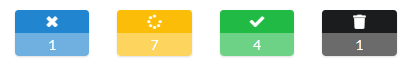
- Blue - the number of node instances that are not initialized
- Yellow - the number of node instances that are in active state (includes: initializing, creating, created, configuring, configured, starting, stopping, stopped and deleting)
- Green - the number of node instances that are started
- Black - the number of node instances that are deleted
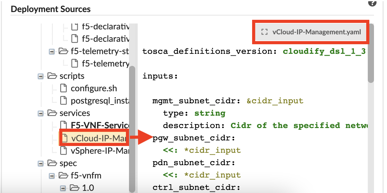
Deployment Sources - displays blueprint source files in a tree view. Click an item in the tree to view the code in the adjacent panel. To open the file in full mode, in the top-right corner of the pane, click the gray box with the source filename.
History
This tab displays a table listing all Deployment Execution details:
Deployment - Blueprint name
Workflow - name of the last workflow executed
Created - date & time stamp deployment was created
Ended - date & time stamp deployment ended
Creator - user name/role who dispatched the deployment
Attributes - workflow attributes used (see, Workflow User Guide for details)
This tab also contains the Deployment Events/Logs pane (see the Events Log topic for complete details).
Update deployments
You can update/change blueprints, input values, and workflow actions for deployed nodes.
In the left menu expand the Deployments blade, and then click the Services options.
In the Services pane select a blueprint for which you want to update, click
Deployment actions, and then select the Update option from the list.In the Update deployment popup window, do the following:
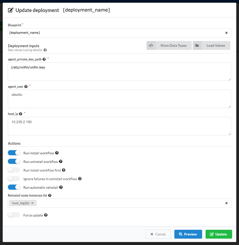
Define a new blueprint for the deployment
Change input values, or define new inputs for this deployment.
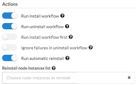
Set the following Actions to take upon this updated deployment like enabling/disabling Install/Uninstall workflows on specific node instances.
Do one of the following:
Click Update to commit all changes.
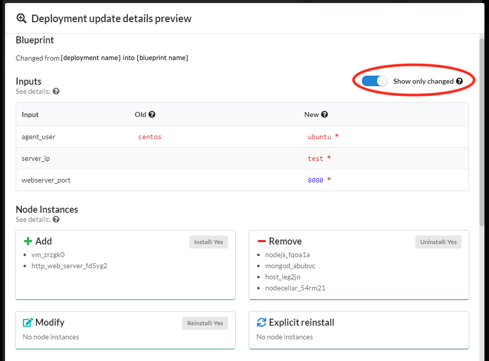
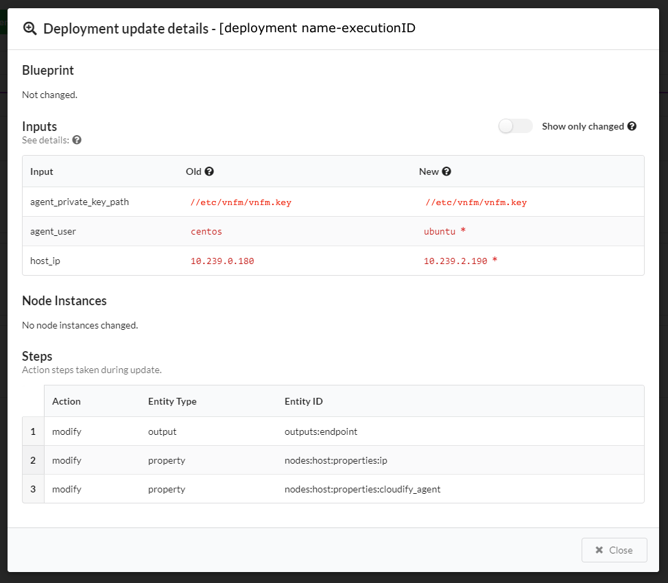
Click Preview to view all changed parameters before committing. In the Preview window slide to enable the Show only changed option, to display only changed parameters like:
- Blueprint
- Inputs
- Node instance
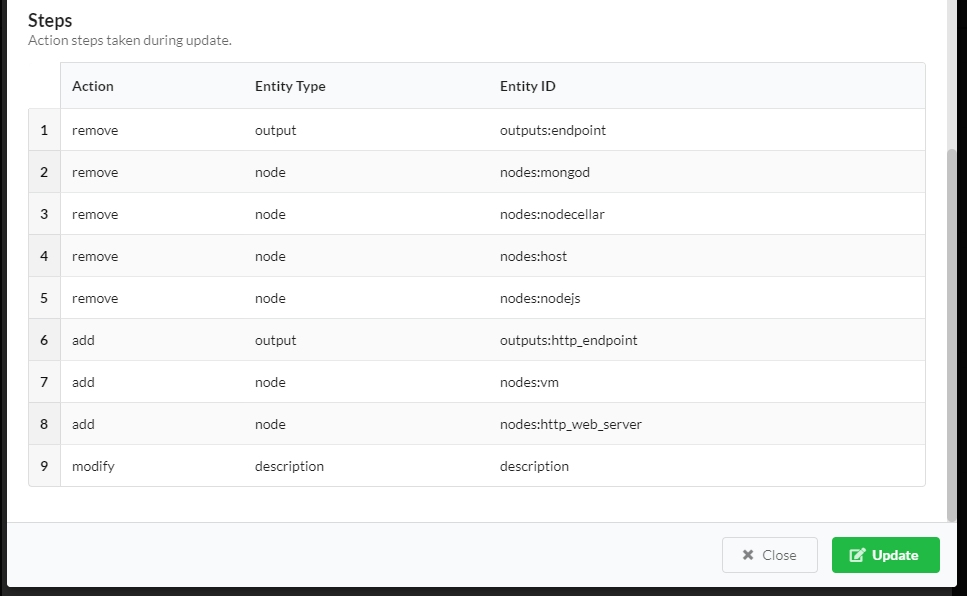
- Actions/Steps to be taken
To view this same information about past updates, click the History tab, or do the following:
- Click the Services blade, click a deployment in the list, and then click Details.
- Click the History tab to view the Deployment Executions widget for the specific deployment.
- In an Execution row, click and select the Show Update Details option
(this option is only available in executions associated with update workflows).
The Deployment update details window appears:
Update deployments using the CLI
Use the following commands to update existing deployments. For complete details, consult the Orchestrator CLI topic.
Updating a deployment via the CLI is similar to creating a deployment, requiring that you supply an argument of the existing deployment’s ID. You must also supply either a blueprint ID or new inputs (or both) for the deployment update to use. The deployment’s blueprint and inputs will update in the data model.
Run the following command to update a deployment (must supply either blueprint id, or new inputs, or both):
vnfm deployments update ID_OF_DEPLOYMENT_TO_UPDATE -b BLUEPRINT_ID -i UPDATED_INPUTSRun the following command to get data about a deployment update:
vnfm deployments get-update DEPLOYMENT_UPDATE_IDRun the following command to list deployment updates (if the deployment id parameter is supplied, then list updates for a specific deployment; otherwise, list updates for all deployments):
vnfm deployments history [-d DEPLOYMENT_ID]
Consult the Orchestrator CLI Deployments usage documentation.
Automatic and manual reinstall
Modified nodes in the update (their properties and/or operations) are changed, and automatically reinstalled,
so the modifications can take affect. You can avoid automatic re-installation of modified nodes, by using
the --skip-reinstall flag. To manually supply a list of node instances you want reinstalled, use
the --reinstall-list or -r parameter. You can pass this parameter multiple times in a single command, or to pass a list of
node instance IDs. Explicitly supplied node instances are reinstalled, even if the --skip-reinstall flag
is supplied (in fact, the --skip-reinstall flag is for skipping only the automatic reinstall of modified nodes).
Note
If you modify required node properties for the node’s uninstallation, you must use
the --skip-reinstall flag, since the reinstall takes place after the properties are updated in the data model, and
the original required properties for the uninstall may no longer exist. If this occurs, either split the update into 2 phases
that are performed in 2 different updates (removing the old nodes and then adding
the updated ones), or to change the node names in the blueprint, so they are treated as different nodes. In case of a plugin update,
to avoid re-installing all nodes installed by the plugin, use the --skip-reinstall flag (especially central deployment plugins;
for example, updating the OpenStack plugin triggers automatic re-installation of all the OpenStack nodes). Consider updating
plugins in a separate deployment update, dedicated for this action only. When changing noon-critical properties for a successful
uninstallation, but can still cause some of the uninstall tasks to fail, use the --ignore-failure flag to ignore
those irrelevant failures, and proceed normally.
Skipping the Install/Uninstall/Reinstall Workflow Executions
You can skip the execution of the install and/or uninstall and/or reinstall workflows during the deployment update process if you skip:
- The install workflow, added nodes are not installed, added relationships are not established but updated agent-host and central-deployment plugins are installed (unless update_plugins is set to False).
- The uninstall workflow, removed nodes are not uninstalled, removed relationships are not unlinked but outdated agent-host and central-deployment plugins are uninstalled (unless update_plugins is set to False).
- The reinstall workflow, modified nodes are not reinstalled automatically (nodes that were manually chosen to reinstall will still be reinstalled).
- The update_plugins workflow, any update plugins (agent-host nor central-deployment) are uninstalled nor installed.
To skip the install execution, run the following command:
vnfm deployments update ID_OF_DEPLOYMENT_TO_UPDATE -b BLUEPRINT_ID --skip-install
To skip the uninstall execution, run the following command:
vnfm deployments update ID_OF_DEPLOYMENT_TO_UPDATE -b BLUEPRINT_ID --skip-uninstall
To skip the automatic reinstall execution, run the following command:
vnfm deployments update ID_OF_DEPLOYMENT_TO_UPDATE -b BLUEPRINT_ID --skip-reinstall
To skip installing or uninstalling the plugins, use the following command:
vnfm deployments update ID_OF_DEPLOYMENT_TO_UPDATE -b BLUEPRINT_ID --dont-update-plugins
Manually supplying node instances to reinstall
You can explicitly supply a list of node instance ids to be reinstalled as part of the update. They will be added to the list of modified node instances that need to be reinstalled. Even if the flag –skip-reinstall was supplied, the nodes that were explicitly passed to the reinstall list will be reinstalled.
To manually supply node instance ids to reinstall, run the following command (the parameter is passed multiple times as
either --reinstall-list, or simply -r, to form a list of node instances to reinstall):
VNFM deployments update:
ID_OF_DEPLOYMENT_TO_UPDATE -b BLUEPRINT_ID --reinstall-list NODE_INSTANCE_ID_1 -r NODE_INSTANCE_ID_2 -r NODE_INSTANCE_ID_3 --reinstall-list NODE_INSTANCE_ID_4In this case, when the update takes place all the nodes that were modified and all the nodes that were passed to the list are reinstalled. If a node instance ID is illegal (the node instance either does not exist, about to be installed, or about to be uninstalled) an error occurs, and the update fails.
To manually supply node instance ids to reinstall, while avoiding the automatic reinstall, run the following command:
vnfm deployments update ID_OF_DEPLOYMENT_TO_UPDATE -b BLUEPRINT_ID --reinstall-list NODE_INSTANCE_ID_1 -r NODE_INSTANCE_ID_2 --skip-reinstallIn this case, only the node instances explicitly passed
(NODE_INSTANCE_ID_1, NODE_INSTANCE_ID_2)are reinstalled. The modified node instances are not automatically reinstalled.
Ignoring failures while uninstalling nodes
When running uninstall (including uninstall as part or a reinstall) there are two possible ways of handling a recoverable error in a task:
- Like any other workflow, retry the task until it succeeds (and then move on to the next task), or until reached the maximum retries number (and then fail the execution). This is the default behavior.
- Ignore the failure and simply move on to the next task (this method assumes that a failure in the Uninstall workflow is
not critical and has no negative affect). This behavior is used when the parameter
ignore_failureis set to true.
To set ignore_failure to true (by passing the –ignore-failure flag), run the following command:
vnf deployments update ID_OF_DEPLOYMENT_TO_UPDATE -b BLUEPRINT_ID --ignore-failure
In this case, all failures in tasks that are part of uninstalling nodes are ignored, and the update continues as planned.
You can use this in other situations, for example:
- Some of the nodes that has to be uninstalled/reinstalled are damaged and their uninstallation may not work perfectly.
- The nodes that are being uninstalled have properties that were modified in this update and are being used at the nodes uninstall workflow (but not necessarily critical to its success) and the fact that they were modified may fail some tasks.
- This update is a roll-back after a failing update; therefore, some of its tasks will fail (uninstallation of nodes that were not installed properly in the original update).
Recovering from a Failed Update
If a deployment update workflow fails during its execution, perform a “rollback” in order to recover. A common solution is to update the deployment with a blueprint which represents the previous (state of the) deployment. In order to do that make sure there is no running update workflow for your deployment. Look for the latest update workflow on the list:
vnfm executions list -d DEPLOYMENT_ID
You will find more information on cancelling workflow executions on a dedicated page of this documentation.
The next (and the final) step of recovery opration is performing a deployment update with the original blueprint.
The --reevaluate-active-statuses flag will help to make sure that the status of previous deployment update is aligned
with the status of relevant execution.
To force a deployment update execution, run the following command:
vnfm deployments update ID_OF_DEPLOYMENT_TO_UPDATE -b ID_OF_THE_ORIGINAL_BLUEPRINT_BEFORE_THE_FIRST_UPDATE --reevaluate-active-statuses
As mentioned before, in this situation it makes sense to also use the –ignore-failure flag, like:
vnfm deployments update ID_OF_DEPLOYMENT_TO_UPDATE -b ID_OF_THE_ORIGINAL_BLUEPRINT_BEFORE_THE_FIRST_UPDATE --reevaluate-active-statuses --ignore-failure
Changing execution order
By default, the update workflow first uninstalls deleted nodes, then installs added nodes and at last - reinstalls modified nodes. The –install-first flag can be used to run install before uninstall (not recommended since some resources required for the nodes that are about to be installed may still be taken by the nodes that are about to be uninstalled).
To update a deployment with install running before uninstall, run the following command:
vnfm deployments update ID_OF_DEPLOYMENT_TO_UPDATE -b BLUEPRINT_ID --install-first
To update a deployment with the old behavior, before version 4.4 (install running before uninstall, and reinstall not running at all), run the following command:
vnfm deployments update ID_OF_DEPLOYMENT_TO_UPDATE -b BLUEPRINT_ID --install-first --skip-reinstall
Providing Inputs
You can provide new inputs while updating a deployment. You provide the inputs in the same manner as when creating a deployment, with the following important distinctions:
Overriding inputs
If you provide an input with the same name as an existing deployment input, it overrides its value. Other new inputs will be added to the data model as usual.
Example: Overriding inputs of existing nodes
Assume that you have the following node in your deployment, and that the port input has a value of 8080:
webserver:
    [...]
    properties:
        port: {get_input: port}
Any new nodes (including new webserver nodes) that were added as a part of that deployment update and use the port input, are assigned with the new port input value - 9090.
The overriden input will cause a modification in the webserver node (his port property was changed). This will trigger
an automatic reinstallation of all the instances of the webserver node, so the updated port will take affect. If the --skip-reinstall
flag was passed, automatic reinstall will not be triggered, and although the input was overriden to 9090, the actual port on
the existing server will remain 8080.
Referencing Existing Resources and Uploading New Ones
Since the blueprint has to be uploaded before using it to update the deployment, it has to be a valid blueprint that can be used to create new deployments as well. Therefore, each resources that are being used in this blueprint must be imported or attached to it (cannot rely on resources from the original deployment blueprint). Any resource (scripts, data files, etc.) that will be uploaded with the same name as a resource in the original deployment, will overwrite it. However, entries from the imports section that were part of that deployment’s blueprint, or of a previous deployment update, must also be a part of the deployment update blueprint.
Automatically correcting old inputs’ types
In case you are trying to update a deployment but cannot because of an error similar to this one:
dsl_parser.exceptions.DSLParsingException: Property type validation failed in 'delay': the defined type is 'integer', yet it was assigned with the value '20'
Use the --auto-correct-types flag along with vnfm deployments update. It’s purpose is to automatically convert old
inputs values’ types from string to integer, float or boolean, based on the type of the input declared in a blueprint.
Unsupported Changes in a Deployment Update
If a deployment update blueprint contains changes that are not currently supported as a part of an update, the update is not executed, and a message indicating the unsupported changes will be displayed to the user. Following is a list of unsupported changes, together with some possible examples.
Node Type
You cannot change a node’s type.
# original deployment blueprint
node_templates:
    node1:
        type: my_type
# deployment update blueprint
node_templates:
    node1:
        type: my_updated_type  # unsupported update - can't modify a node's type!
contained_in Relationship Target
You cannot change the target value of a vnfm.relationships.contained_in type relationship, or any type from which it derives.
# original deployment blueprint
node_templates:
    node1:
        relationships:
          - type: vnfm.relationships.contained_in
            target: node2
# deployment update blueprint
node_templates:
    node1:
        relationships:
          - type: vnfm.relationships.contained_in
            target: node3  # unsupported update - can't modify a contained_in relationship's target
Relationship Properties
You cannot change a relationship’s property, for example, connection_type.
# original deployment blueprint
node_templates:
    node1:
        relationships:
          - [...]
            properties:
                connection_type: all_to_all
# deployment update blueprint
node_templates:
    node1:
        relationships:
          - [...]
            properties:
                connection_type: all_to_one  # unsupported update - can't modify a relationship's property
Groups, Policy Types, and Policy Triggers
You cannot make changes in the top level field groups, policy_types and policy_triggers as a part of a deployment
update blueprint.
What Can be Updated as a Part of a Deployment Update
The following can be updated as part of a deployment update, subject to the limitations that were previously described in the Unsupported Changes section.
Nodes
You can add or remove nodes, including all their relationships, operations, an so on. Remember that adding or removing a node triggers the install/uninstall workflow in regard to that node.
Assume that the original deployment blueprint contains a node named node1. Then, in the deployment update blueprint, you decide to ‘rename’ that node, to node2. Now the deployment update blueprint’s node2 is identical to node1 in the original blueprint, except for its name. But in practice, there isn’t really a ‘renaming’ process. In this scenario, node1 is uninstalled and node2 is installed, meaning that node1 does not retain its state.
# original deployment blueprint
node_templates:
    node1:
        [...]
# deployment update blueprint
node_templates:
    node2:  # node1 will be uninstalled. node2 will be installed
        [...]
Relationships
With the exception of being added or removed as part of adding or removing a node, you can add or remove relationships independently. Adding a relationship triggers an execution of its establish operations (assuming a default install workflow). Similarly, removing a relationship triggers an execution of the unlink operations. You can also change a node’s relationship order. The operations of the added and removed relationships are executed according the order of the relationships in the deployment update blueprint.
# original deployment blueprint
node_templates:
    node1:
        relationships:
          - type: vnfm.relationships.connected_to
            target: node2
# deployment update blueprint
node_templates:
    node1:
        relationships:
          - type: vnfm.relationships.connected_to
            target: node3  # the previous relationship to node2 will be removed (unlinked), and a new relationship to node3 will be added (established)
Operations
You can add, remove or modify node operations and relationship operations.
# original deployment blueprint
node_templates:
    node1:
        interfaces:
            interface1:
                operation1:
                    implementation:
                        plugin1.path.to.module.taskA
                operation2:
                    implementation:
                        plugin2.path.to.module.taskA
        relationships:
          - [...]
            source_interfaces:
                interface1:
                    operation1:
                        implementation:
                            plugin1.path.to.module.taskB
plugins:
    plugin1:
        [...]
    plugin2:
        [...]
# deployment update blueprint
node_templates:
    node1:
        interfaces:
            interface1:
                operation1:
                    implementation:  # modified operation1 (changed implementation)
                        plugin1.path.to.module.taskB
                # removed operation2
                operation3:  # added operation 3
                    implementation:
                        plugin2.path.to.module.taskB
        relationships:
          - [...]
            source_interfaces:
                interface1:
                    operation1:
                        implementation:  # modified operation1 (changed implementation to a different plugin)
                            plugin2.path.to.module.taskC
plugins:
    plugin1:
        [...]
    plugin2:
        [...]
Properties
You can add, remove, or modify properties. Overriding a default property value is treated as a property modification.
# original deployment blueprint
node_templates:
    node1:
        type: vnfm.nodes.Compute
    node2:
        type: my_custom_node_type
        properties:
            prop1: value1
# deployment update blueprint
node_templates:
    node1:
        type: vnfm.nodes.Compute
        properties:
            ip: 192.0.2.1  # modified the property by overriding its default (from types.yaml)
    node2:
        type: my_custom_node_type
        properties:
            # removed property prop1
            prop2: value2  # added property prop2
Outputs
You can add, remove or modify outputs.
# original deployment blueprint
outputs:
    output1:
        value: {get_input: inputA}
    output2:
        [...]
# deployment update blueprint
outputs:
    output1:
        value: {get_input: inputB}  # modified the value of output1
    # removed output2
    output3:  # added output3
        [...]
Workflows
You can add, remove or modify workflows.
# original deployment blueprint
workflows:
    workflow1: plugin_name.module_name.task1
    workflow2:
        [...]
# deployment update blueprint
outputs:
    workflow1:
        value: plugin_name.module_name.task2  # modified the value of workflow1
    # removed workflow2
    workflow3:  # added workflow3
        [...]
Plugins
You can add, remove or modify plugins.
# original deployment blueprint
imports:
  - plugin:plugin-name-1?version=1.0
  - plugin:plugin-name-2?version=1.0
# deployment update blueprint
imports:
  - plugin:plugin-name-1?version=2.0
  - plugin:plugin-name-3?version=1.0
In this example, plugin-name-1 will be updated from version 1.0 to version 2.0, plugin-name-3 will be added to the deployment, and plugin-name-2 removed from it.
In cases of updating a plugin that was used to install nodes in the deployment (for example, Openstack plugin used to
install Openstack nodes), the plugin update may trigger automatic reinstallation of those nodes. It can be avoided by
using the --skip-reinstall flag.
Note
You can import plugins stating some version range or no version specifications at all. In this case, use the plugin with the newest version within that range and a matching name and distribution. In the case, where no version specifications is used, the newest plugin version is used with a matching name and distribution. The plugin is being associated with the blueprint, when the blueprint is uploaded, so it is possible that the same blueprint was uploaded twice, is associated each time with a different plugin version. When updating a deployment with a specific blueprint, the plugins used in the deployment after the update are those associated with the blueprint. You can update a plugin’s version in a specific deployment by uploading the same blueprint again without any changes, assuming a newer plugin is available. This version update can also happen unintentionally and deserves consideration.
Updating plugins for a collection of deployments
If you want to perform an update for all the deployment of some blueprint, and update only their plugins, you can perform a plugins update. You can find more information on the CLI command here.
Description
You can add, remove or modify the description.
Adding a description:
# original deployment blueprint
# no description field
# deployment update blueprint
description: new_description  # added description
Removing a description:
# original deployment blueprint
description: description_content
# deployment update blueprint
# removed the description
Modifying a description:
# original deployment blueprint
description: old_description
# deployment update blueprint
description: new_description
Resources
In the left menu click the Resources blade to view the following tabs:
Use the Secret Store
The secrets store provides a secured variable storage (key-value pairs) for data that you do not want to expose in plain text in F5 VNFM blueprints, such as login credentials for a platform. The values of the secrets are encrypted in the database. The system uses the Fernet encryption of cryptography library, which is a symmetric encryption method that makes sure that the message encrypted cannot be manipulated/read without the key. To create a secret, use a text string for the key value, or use a file that contains the key value. The secret store lets you make sure all secrets (for example, credentials to IaaS environments) are stored separately from blueprints, and that the secrets adhere to isolation requirements between different tenants. You can include the secret key in your blueprints and not include the actual values in the blueprints.
Secrets with a hidden value
All the values of the secrets are encrypted in the database. When you create a secret you can specify if you want its value to be hidden or exposed. A secret with a hidden value means the value is only shown to the user who created it, tenant managers and sys-admins. Users can use the secret according to the user roles and the visibility of the secret. Creators and Admins are the only users that can perform any type of update to the secret.
Update a secret with a shown value
- Updating the secret’s value and visibility or deleting the secret is allowed according to the user roles and the visibility of the secret.
- The secret’s Creator and Admins are the only users that can update the secret’s visibility and the “is_hidden” attribute.
Update a secret with a hidden value
Only the creator of the secret and a sys-admin can access, update, or delete the secret with a hidden value (unlike a secret with an exposed value, which other users in the tenant can also update or delete).
Create a secret from the CLI
You can use the vnfm secrets command to manage VNFM secrets (key-value pairs) in the F5 VNF Manager ONLY.
$ vnfm secrets create test -s test_value …

Secret ``test`` created

…
Create a secret from the F5 VNFM Console
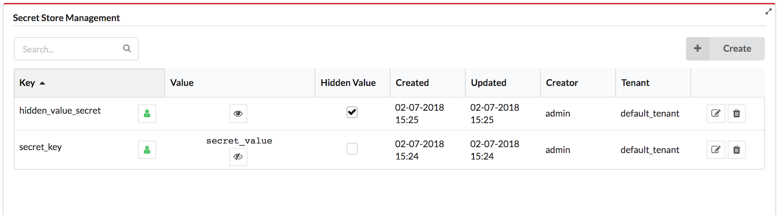
Secret Store Management is performed from the System Resources page in the VNFM Console.
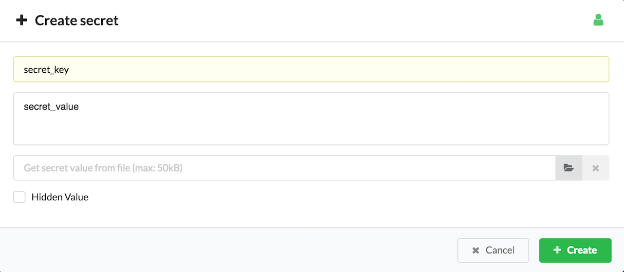
Click Create in the Secret Store Management widget.
Insert the following values:
- The secret key
- The secret value (or select the secret file from your file repository)
- The visibility level, which is the icon of the green man. Click this icon to toggle visibility settings between tenant (green man), private (red padlock), and global (blue earth).
- If the value of the secret should be hidden
Click Create.
Click
 for viewing the secret value.
To change the visibility level of the secret, click
in the key row.To hide the secret value, select the Hidden Value checkbox.
For updating the secret value, click
 in the key row.
Site Management
In the left-side menu click the Resource blade, and then click the Sites tab which displays a list of all sites and enables you to create, update, and delete sites.
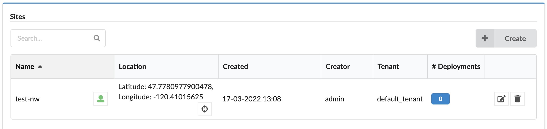
Each site in the list includes the following:
- Name
- Visibility level - Click the icon next to the name, to permit users
(the sites’s creator, sys admins, or tenant managers of the current tenant) to set the visibility as a private/visible resource.
- Location - The location of the site, represented by latitude and longitude. Hovering over
 opens
a popup with small map and marked locations.
opens
a popup with small map and marked locations. - Created - Site creation time
- Creator - Site creator (user)
- Tenant - The name of the tenant the site belongs to (if the site is global, it can belong to a tenant different than the current one).
- Number of deployments assigned to the site.
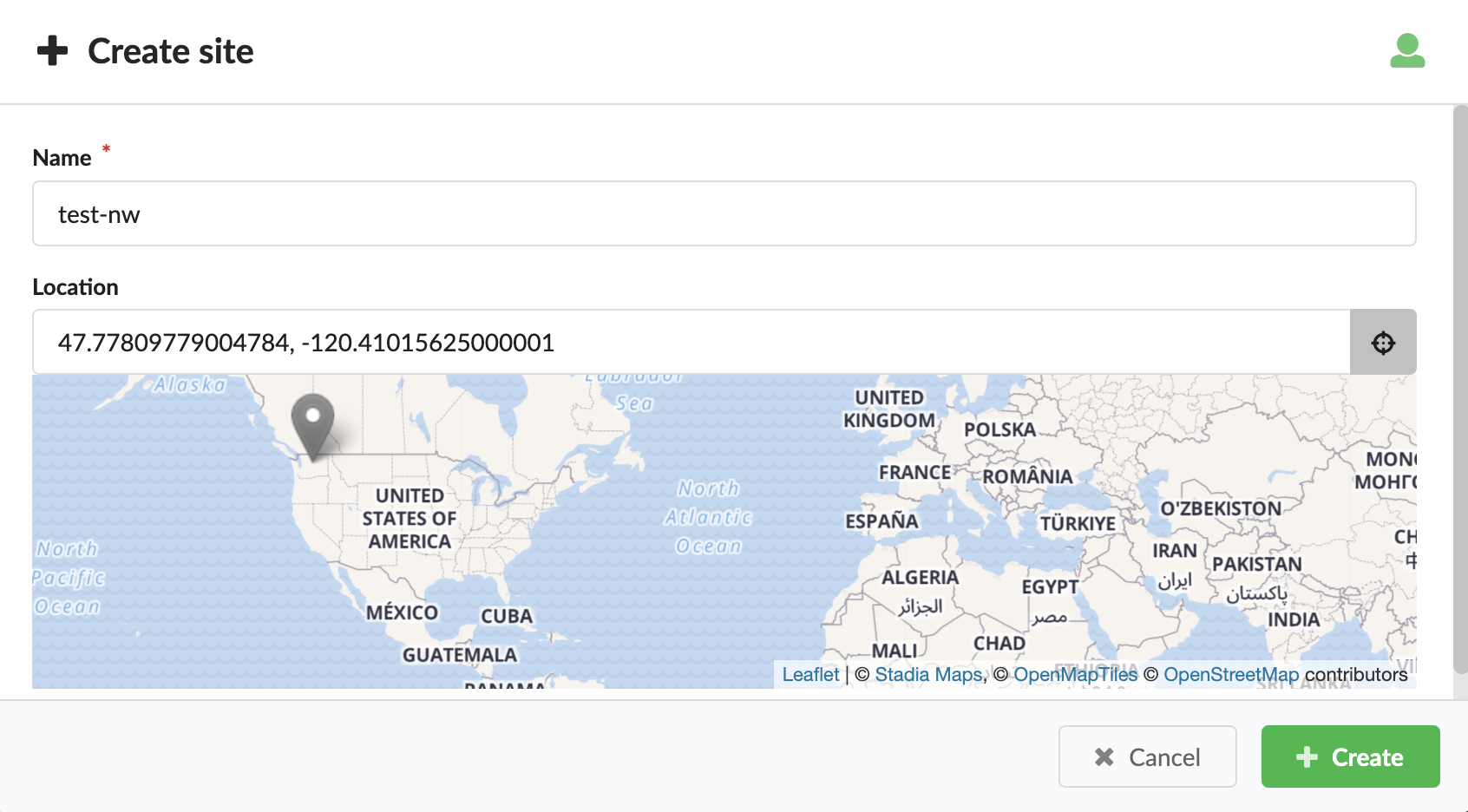
To add and manage sites
To create new site, in the top-right corner of the tab, click Create, and then enter a name and location for the site. The name must be unique in the scope of the site (tenant/global).
To manage existing sites, in the right column of each site row click
Edit to change the site name and/or location or
click Delete the site (if you have the correct permissions), and then click Update.
Deleting a site will remove the assignment of this site from all assigned deployments.In the Location text box click
to select the location from the map, or paste coordinates
into the text box. Expected format: latitude, longitude such as 32.071072, 34.787274.Optional, to choose the visibility level click
repeatedly and set to one of the following:- Tenant resource
- Global
- Private
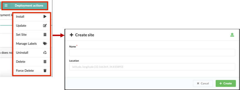
Set site for a deployment
You can set a site for already deployed nodes.
Click the Services blade.
Select a deployment node for which you want to set a site, and then click
Deployment actions.Select the Set Site option from the list, and then in the Site name text box, enter the site where this deployed node resides, and then click Update.
Agents management
Click the Resources blade, and then click the Agents tab to view the following information about a specific agent:
- Id - unique identifier of the agent
- IP - IP address of the agent host
- Deployment - Deployment ID associated with agent
- Node - Node ID associated with agent
- System - agent host operation system
- Version - agent version
- Install Method - agent installation method (one of described here)
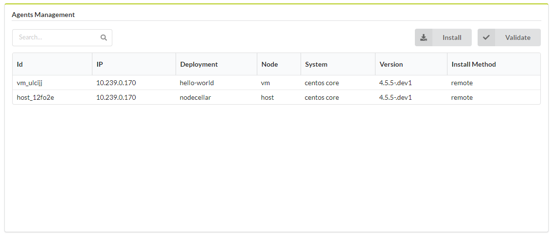
Click the following to execute the following operations:
 Install - executes install_new_agents workflow on selected deployment. Enables you to define
Manager IP, Manager Certificate, stop old agents and filter by node(s), node instance(s) and install method(s).
Install - executes install_new_agents workflow on selected deployment. Enables you to define
Manager IP, Manager Certificate, stop old agents and filter by node(s), node instance(s) and install method(s). Validate - executes
 validate_agentsworkflow on selected deployment. Enables you to filter by node(s), node instance(s) and install method(s).
Learn more about agents here.
Settings
- Refresh time interval - The time interval in which the widget’s data will be refreshed, in seconds. Default: 15 seconds
- List of fields to show in the table - List of columns to be shown in list of agents table. Some of the fields may be hidden depending on the context, eg. when Deployment ID is set in context then Deployment field will be hidden.
- Filter Agents by Install Method - Install Methods to filter Agents. Unset all options to disable this type of filtering. Default value: No filtering by Install Methods.
Agents
The VNFM Agent is a component that is installed on hosts that are part of your blueprint. The VNFM Agent communicates with the VNF Manager.
The Agent execute orchestration operations locally, and collects metrics and report them to the VNF Manager.
If your blueprint does not require these functions, you can exclude the agent installation from the VNF Manager installation process.
Agent Packages
VNFM Agent is supported over the following platforms:
- RHEL / CentOS 6.x (Python 2.6)
- RHEL / CentOS 7.x (Python 2.7)
- Ubuntu 14.x / 16.x / 18.x (Python 2.7)
- Windows 2008 and later (Python 2.7)
- In addition, you can use the VNFM Agent Packager in case you need an agent package for other Linux platforms.
Note
- For Linux platforms, you must have Python installed on the image at the time of the agent installation.
- If your image does not include Python, you can use initialization scripts supported by VNFM (userdata on OpenStack, Customization Scripts on AWS, etc.) to install Python.
- For Windows, the agent installer is bundled with a Python interpreter.
Communication with the VNF manager
The agent requires access to the manager with these services:
- TCP Port 53333 (REST API; HTTPS)
- TCP Port 53229 (file server; HTTPS)
- TCP Port 5671 (RabbitMQ; AMQP over TLS)
By default, the VNFM Agent connects to the private IP of the VNF Manager as specified in the Manager installation. You can change the ports used by these services if necessary, such as in a multi-cloud environment.
Installation script
The same installation script is used in all of the installation methods. This is either a bash script on Linux or a PowerShell script on Windows. The script is agent-specific, and a separate script is rendered from a template for each agent during the install workflow. The script downloads the agent package from the manager (over port 53333), extracts it on the agent host, creates a daemon and starts it.
Installation methods
There are methods by which the installation script is distributed to the agent host and executed.
remote (default)
In this method, the installation script is pushed to the agent host, and executed remotely using SSH on Linux hosts and WinRM on Windows hosts. This is the default and simplest way for systems that allow SSH/WinRM access. The pre-requisites for remote installation are:
- For Linux, an SSH server must be running on the agent host, and the SSH port (22 by default) must be open for incoming connections.
- For Windows, WinRM must be enabled, and the WinRM port (5985 by default) must be open for incoming connections.
To enable WinRM, the following commands must be executed on the host (for example, in userdata).
winrm quickconfig -q
winrm set winrm/config              @{MaxTimeoutms="1800000"}
winrm set winrm/config/winrs        @{MaxMemoryPerShellMB="300";MaxShellsPerUser="2147483647"}
winrm set winrm/config/service      @{AllowUnencrypted="true";MaxConcurrentOperationsPerUser="4294967295"}
winrm set winrm/config/service/auth @{Basic="true"}
netsh advfirewall firewall add rule name="WinRM 5985" protocol=TCP dir=in localport=5985 action=allow
Note
- The previous commands are provided in a syntax that is suitable for invocation from a command-prompt window. If using userdata (or an equivalent feature), adjust the commands to accommodate its requirements (for example: if you want these commands to run within a batch file, prefix each line with call).
- The commands are permissive and you must adjust them according to your requirements. These settings provide unencrypted
WinRM access to the machine (from the MSDN documentation:
AllowUnencrypted- Enables the client computer to request unencrypted traffic).
The output (both standard output and standard error streams) generated during the agent installation process is accumulated in memory, and echoed to VNFM logs once the agent installation is completed.
init_script
For systems that don’t have SSH/WinRM access, userdata (e.g. cloud-init) may be used. In this method, an install script is rendered, and a temporary link pointing to it is created. This link is then embedded in a separate download script, which is injected into the agent host’s userdata. When the host is booted for the first time, the download script is executed. It downloads the installation script from the temporary link and executes it. To use the init_script method, the IaaS provider and VNFM plugin need to support userdata. Currently, the Openstack, AWS and AWS-SDK plugins support this installation method.
The output generated during the agent installation process is not echoed to VNFM’s logger; instead, you can find it in:
- On Linux: /var/log/cloudify/agent-install.log
- On Windows: %AppData%vnfm-agent-install.log (where %AppData% resolves based on the user account that runs the initialization script)
plugin
For systems that have neither SSH/WinRM access, nor the ability to inject a script into userdata, the plugin installation method allows implementing a custom way to download and execute the installation script. In this method, a temporary download link for the installation script is created and made available to the plugin using the ctx. It is up to the plugin’s developer then to implement a custom method for downloading and executing the installation script on the agent’s host.
provided
For systems that require the agent to be embedded in the image, users can use the provided method. In this mode, it is up to the user to make sure the agent is already installed on the image. During the install workflow, a configuration script will be rendered and a temporary link to it will created and made available via VNFM’s logs (reading the logs is the only way to retrieve the temporary link). This script is similar to the installation script, except that it doesn’t download or install the agent package, but only configures and starts the agent daemon. This script needs to be downloaded and executed manually for every agent.
none
In some cases, you cannot or prefer not to install an agent on VNF-managed VMs. This is due to a security restriction, or because a VM is a pre-configured, closed appliance that you cannot access or modify.
This has the following implication:
- It is not possible to run operations that have the executor field set to host_agent (such as the Script plugin).
- In the case of script invocation, use a workaround to use the Fabric plugin (which runs scripts or commands by establishing an SSH connection and running scripts or commands through that).
Specifying the Installation Method
To specify the installation method that you will use, set the install_method key in the agent_config structure.
For example, set the install_method as a property on the compute node’s template, like:
node_templates:
  my_vm:
    type: vnfm.nodes.Compute
    properties:
      agent_config:
        install_method: remote
Configuration Locations
Agent configuration consists of locations that all adhere to the same schema. The schema is based on the
vnfm.datatypes.AgentConfig datatype, which is defined in the standard types.yaml file.
The order in which each property is resolved is as follows:
Operation Inputs
If a property has been provided as part of the operation inputs in agent_config (or the deprecated vnfm_agent), it is used. For example:
node_templates:
  my_vm:
    type: vnfm.nodes.Compute
    interfaces:
      vnfm.interfaces.vnfm_agent:
        create:
          inputs:
            agent_config:
              # configuration goes here
              user: centos
              ...
Node Instance Runtime Property
If the agent to be installed is a host agent (and not a central deployment agent), and the property is provided as part of the vnfm_agent node instance runtime property, it is used.
Node Property
If the agent to be installed is a host agent (and not a central deployment agent), and the property has been provided as part of the agent_config (or the deprecated vnfm_agent) node property, it is used. For example:
node_templates:
  my_vm:
    type: vnfm.nodes.Compute
    properties:
      agent_config:
        # configuration goes here
        user: centos
        ...
Installation Context
If the property has been provided during manager installation as part of the agent section in the config.yaml file, it is used. For example, consider the following excerpt from a config.yaml file:
...
agent:
  networks:
    some_network: 10.0.0.1
  min_workers: 2
  max_workers: 5
...
You can use this section to specify a global agent configuration that will apply to all installed agents.
Configuration properties:
| NAME | TYPE | DESCRIPTION |
|---|---|---|
| user | string | For Linux agents, this is the user account for which the agent service will be installed. If the agent installation method is remote, then this user will also be used for SSH’ing to the agent host. For Windows agents, this parameter is only applicable when the installation method is remote, and it is used by WinRM to connect to the agent host. |
| key | string | For Linux agents installed with the remote method, this may be either the path to the private key that will be used to connect to the host, or the actual private key (beginning with “—–BEGIN RSA PRIVATE KEY—–”). |
| password | string | For the remote installation method, define the password to authenticate with. For Linux hosts, this property is optional if the key property is provided. For Windows hosts, this property is also optional, depending on whether the password runtime property has been set by the relevant IaaS plugin, prior to agent installation. |
| port | integer | For the remote installation method, this is the port used to connect to the host. The default values are 22 for Linux hosts and 5985 for Windows hosts. |
| min_workers | integer | Minimum number of agent workers. By default, the value is 0. See Auto Scaling for further details. Note: For Windows-based agents, this property is ignored and min_workers is set to the value of max_workers. |
| max_workers | integer | Maximum number of agent workers. By default, the value is 5. For Linux based agents, |
| disable_requiretty | boolean | disables the requiretty setting in the sudoers file. By default, this value is true. |
| process_management | dictionary | Process management specific configuration. |
| network | string | Optional name of the network to use when communicating with the manager. The mapping of network names to IPs/hostnames is specified during manager installation. If not specified, the manager’s private IP will be used. |
| extra_env_path | string | Optional path to a file (on the agent host) containing environment variables to be added to the agent’s process. The file should be in the format of multiple export KEY=VALUE lines for Linux, or set KEY=VALUE for Windows. |
| extra | dictionary | Optional additional low-level configuration details. |
| executable_temp_path | string | An alternative path to use for temporary executable files (default is /tmp). Useful for environments where /tmp is mounted with noexec for security purposes. |
| log_level | string | The logging level for the VNFM Agent service. Can be any of the following values: critical, error, warning, info, debug. The default is debug. The default is info. |
| log_max_bytes | integer | Maximum size of agent log file, in bytes, before rotation takes place (default: 5*1024*1024 (5MB)). |
| log_max_history | integer | Number of historical log files to maintain (default: 7). |
| heartbeat | integer | AMQP heartbeat interval in seconds, 0 means disabled (default: 0). |
Extra configuration properties (that go under the extra property):
| NAME | TYPE | DESCRIPTION |
|---|---|---|
| distro | string | Linux operation system distribution. |
| distro_codename | string | Linux operation system distribution release. |
| package_url | string | Specify an explicit URL from which to download the agent package. |
| uri | string | For Windows-based agents, WinRM URI. By default, the value is wsman. |
| protocol | string | For Windows-based agents, WinRM protocol. By default, the value is http. |
| transport | string | For Windows agents installed with the remote installation method only: defines the WinRM transport
to use (valid values are outlined here:
https://github.com/diyan/pywinrm/tree/v0.3.0#valid-transport-options |
| fabric_env | dictionary | For Linux-based agents, configure fabric that is used to SSH into the remote host. |
Process Management
Additional configuration can be supplied to the service manager that will be used to manage the installed agent by using the process_management property.
Linux init.d Process Management:
| NAME | TYPE | DESCRIPTION |
|---|---|---|
| start_on_boot | boolean | Specifies whether the agent service should be restarted after a system reboot. By default, the value is true. |
Windows NSSM Process Management:
| NAME | TYPE | DESCRIPTION |
|---|---|---|
| startup_policy | string | Specifies the start type for the service. By default, the value is auto. |
| failure_reset_timeout | integer | The reset value passed to sc failure during service configuration. By default, the value is 60. |
| failure_restart_delay | integer | Specifies delay time (in milliseconds) for the restart action. By default, the value is 5000. |
| service_user | string | Specifies the user account that the service should run with. If not specified, then LOCALSYSTEM is used. The format should be DOMAINusername. For a local user, use a dot (.) for the domain. |
| service_password | string | Specifies the password for the user account specified by service_user. If not specified, then an empty string is used. |
Linux Agent Package Resolution
In most cases, the agent package that will be used to install the agent is automatically resolved and does not require manual configuration. However, a mechanism exists that enables the implicit resolution to be overwritten. Following is a short description of the implicit resolution mechanism and details about how to override the implicit resolution with hard-coded values.
The install process attempts to identify the distribution and its release, and to deploy the correct type of agent for them. The identification process is based on Python’s platform.dist(). The system references the first attribute of the tuple returned by this call as distro, and the third attribute as distro_codename. For example, making this call on Ubuntu trusty returns a tuple in which the distro attribute is Ubuntu and the distro_codename attribute is trusty. After making the call, the package name that is downloaded from the management file server is {distro}-{distro_codename}-agent.tar.gz, where distro and distro_codename are converted to lowercase characters. In the case of Ubuntu trusty, the package name is ubuntu-trusty-agent.tar.gz.
If distro, distro_codename, or package_url are provided explicitly in the extra agent configuration, they will be used instead of the implicit mechanism.
AGENT PACKAGER
The VNFM Agent is a virtual environment in which a series of modules are installed and (optionally) to which some configuration files are attached.
To use VNFM with distributions other than the officially supported ones, an Agent Packager tool is provided to assist you to create agents for your distributions.
The purpose of the tool is to:
- Address the issues related to compiling module requirements on different distributions, by bridging the gap between user-compiled images, unfamiliar/minor distributions, and so on.
- Enable you to create your own VNFM Agent with your custom plugins.
- Make the agent creation process seamless in terms of there being a single configuration file and a single-line command.
- Enable you to override existing mandatory (and other) modules, by providing your own.
You can use the VNFM Agent packager to create an agent on the distribution on which you are running, that uses your distribution and compilers for modules that require compilation.
Note
- You must use Python 2.7.x or Python 2.6.x to create an agent.
- Not all VNFM plugins can run on Python 2.6.x. Only basic modules and plugins currently run on Python 2.6.x. To determine whether a plugin supports your Python version, refer to the documentation for the plugin you plan to use.
Creation Process
During the creation process, the agent-packager performs the following actions:
- Creates a virtualenv using your selected Python binary.
- Installs mandatory external modules into the virtualenv.
- Installs modules from a provided requirements.txt file.
- Installs mandatory and optional VNFM plugins and modules into the virtualenv.
- Installs the vnfm-agent module into the virtualenv.
- Installs any additional user-selected VNFM plugins and Python modules into the virtualenv.
- Validates that all specified modules are installed.
- Generates an included_plugins.py file. The file is used by the vnfm-agent module to automatically load all plugins specified in the file.
- Creates a TAR file containing the virtualenv.
Note
The tool creates a TAR file for use in VNFM Linux-based environments. For other environments, a different type of agent is required.
Installation
pip install vnfm-agent-packager
Usage
Important
- You must use this tool on the specific version of the distribution on which you intend your agent to run, as it can require compilation.
- You must have the required version of Python installed on your selected image.
- You must have the tar binary in your distribution (run which tar to verify that you have TAR installed).
Creating the Agent Packager from the CLI:
vnfm-ap -h

Script to run the VNFM Agent Packager via command line

Usage:
    vnfm-ap [--config=<path> --force --dryrun --no-validation -v]
    vnfm-ap --version

Options:
    -h --help                   Show this screen
    -c --config=<path>          Path to config yaml (defaults to config.yaml)
    -f --force                  Forces deletion and creation of venv and tar file.
    -d --dryrun                 Lists the modules to be installed without actually installing them.
    -n --no-validation          Does not validate that all modules were installed correctly.
    -v --verbose                Verbose level logging
    --version                   Displays current version
Example:
vnfm-ap -f -c my_config.yaml -v
Creating the Agent Packager from Python
import agent_packager.packager as vnfmap

config = {}  # dict containing the configuration as given in the yaml file.

vnfmap.create(config=config,
             config_file=None,
             force=False,
             dryrun=False,
             no_validate=False,
             verbose=True)
Note
Using the tool from Python enables you to pass the configuration dictionary directly to the creation method, which enables automation of the agent creation process.
Using the Agent
After creating the agent you can do one of the following:
- Use the Agent on a Per-Node Basis: You can define the paths to the agent TAR file in a blueprint on a per-node basis.
- Install Agents in VNF Manager during Bootstrap: You can provide URLs for agents that you want to provide during VNF Manager bootstrap.
Configuring the Tool
Consult the following example YAML configuration file.
Note
It is important that all modules under core_modules, core_plugins and additional_plugins are written using their actual module names and that dashes are replaced with underscores (for example, the fabric plugin under additional plugins must be called vnfm_fabric_plugin.) If this protocol is not followed, vnfm-agent cannot recognize and load the plugin.
distribution: Ubuntu
release: trusty
python_path: '/usr/bin/python'
requirements_file: path/to/my/requirements/file.txt
vnfm_agent_version: master
vnfm_agent_module: [insert URL]
core_modules:
    vnfm_plugins_common: [insert URL]
    vnfm_rest_client: [insert URL]
core_plugins:
    vnfm_script_plugin: [insert URL]
additional_modules:
    - pyyaml==3.12
additional_plugins:
    vnfm_fabric_plugin: [insert URL]
output_tar: Ubuntu-trusty-agent.tar.gz
keep_virtualenv: true
Explanation of the configuration YAML file:
Note
The distribution and release variables must correspond with the output generated when running:
python -c "import platform; print platform.dist()" # e.g. ('Ubuntu', '14.04', 'trusty')
- distribution - The distribution for which the agent is intended. If this is omitted, the tool attempts to retrieve the distribution by itself. The distribution is then used to name the virtualenv (unless explicitly specified in venv) and to name the output file (unless explicitly specified in output_tar).
- release - The release (for example, precise, trusty) of the distribution for which the agent is intended. If this is omitted, the tool will attempt to retrieve the release by itself. The release is then used to name the virtualenv (unless explicitly specified in venv) and to name the output file (if unless specified in output_tar).
- python_path - Enables you to set the Python binary to be used when creating venv. (Defaults to /usr/bin/python).
- requirements_file - Path to the requirements.txt file that contains the modules you want to be installed in the agent.
- vnfm_agent_version - Specifies the version of the vnfm-agent module to install (not required if vnfm_agent_module is specified). You can use this to create an agent for a specific VNFM version.
- vnfm_agent_module - Specifies the URL from which the vnfm-agent module is to be installed. (Ignores vnfm_agent_version, if specified).
- core_modules - A dict of core modules to install into the virtualenv. (If omitted or with a value of false, the module is installed as a part of the vnfm-agent dependencies.) See a list of current core modules below.
- core_plugins - A dict of core plugins to install into the virtualenv. (If omitted or with a value of false, the module is installed as a part of the vnfm-agent dependencies.) See the following list of core plugins. If exclude is set (per module), it is not installed. Set exclude with caution.
- additional_modules - A list of additional modules to install into the virtualenv. Use this parameter to add additional modules that are not VNFM plugins.
- additional_plugins - A list of additional VNFM plugins to install into the virtualenv.
- output_tar - Path to the TAR file you want to create.
- keep_virtualenv - Specifies whether to keep the virtualenv after creating the TAR file. Default value is false.
Note
All modules and plugins, with the exception of additional_modules and modules inside the requirements_file, are validated.
Agent Modules - Each agent contains a set of Python packages. These modules can be either simple Python libraries, or plugins.
Core External Modules - These are modules, which are not developed by VNFM, that are used by the agent.
- Pika (Mandatory)
Core Modules - These modules are developed by VNFM and provide core functionality for the agent. The default agents provided with VNFM come with these modules pre-installed.
- VNFM REST Client (Mandatory)
- VNFM Plugins Common (Mandatory)
Core Plugins - These plugins are developed by VNFM and provide core functionality for the agent. The default agents provided with VNFM come with these modules pre-installed.
- VNFM Script Plugin (Optional)
The VNF Manager also runs an instance of an agent, which is called the vnfm_management_agent. This agent is responsible for starting all other agents, and therefore requires the following plugin.
VNFM Agent - To use the ZeroMQ proxy in the script plugin, you must explicitly configure it in the additional_modules section, as shown above.
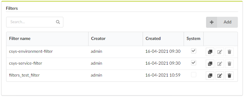
Filters management
Click the Resources blade, and then click the Filters tab to display the list of filter details:
- Filter name - filter ID
- Creator - filter creator
- Created - filter creation date and time
- System - system filter indicator - checked when given filter is a system filter, unchecked otherwise
- Actions column - includes the following buttons:
 Clone/copy filter - opens the filter clone modal allowing to create a modified copy of the selected filter
(see defining filter rules for details on rule definition)
Clone/copy filter - opens the filter clone modal allowing to create a modified copy of the selected filter
(see defining filter rules for details on rule definition)- Edit filter available only to user filters, opens the filter rules edit modal (see defining filter
rules for details on rule definition)
- Delete filter available only to non-system filters, removes the selected filter (see following note)
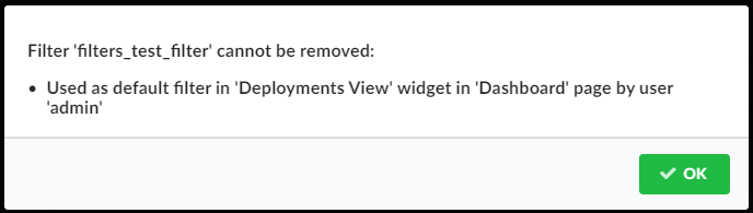
You cannot delete filters used as a default filter in the Deployments View pane. When trying to delete such a filter a modal shows up describing where (on which page and in which widget) and by whom (by which user) the filter is used.
Click Add to open the filter add popup, enabling you to create a new filter by specifying filter ID and filter rules.
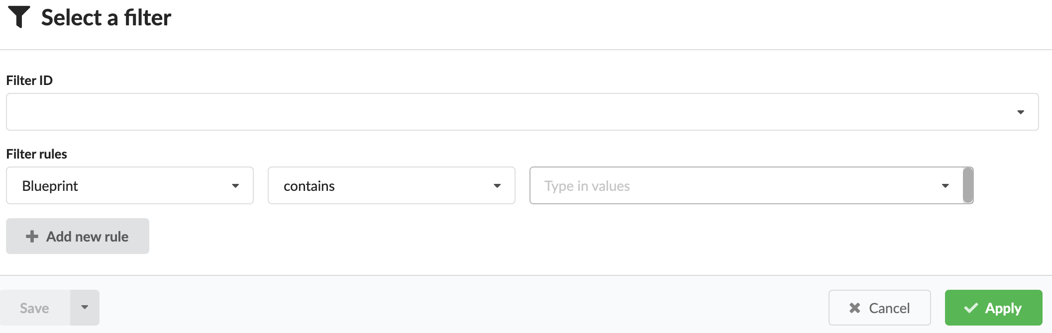
Defining filter rules
Add, edit, and copy to define filter rules.
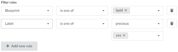
The component presents a list of rows, each representing a single filter rule. Each row contains three inputs:
- Rule type selection dropdown - selecting the context of the rule which can be based on labels or supported deployment attributes such as blueprint ID, site name, or creator.
- Rule operator dropdown. The set of available operators to choose from depends on the selected rule type. See the following tables for details.
- Value input (for attribute rules) or key/value input(s) (for label rules).
Label operator-mapping:
| UI | API | CLI | Applied logic |
|---|---|---|---|
| is one of | any_of | = | The label key matches the specified key and the label value matches one of the specified values. |
| is not one of | not_any_of | != | The label key matches the specified key and the label value does not match any of the specified values. |
| is not one of (or no such key) | is_not | is-not | No label key matches the specified key, or the label key matches the specified key and the label value does not match any of the specified values. |
| key is not | is_null | is null | No label key matches the specified key. |
| key is | is_not_null | is not null | The label key matches the specified key. |
Attributes (blueprint, site name, creator) operator-mapping:
| UI | API | CLI | Applied logic |
|---|---|---|---|
| is one of | any_of | = | The deployment attribute matches one of the specified values. |
| is not one of | not_any_of | != | The deployment attribute does not match any of the specified values. |
| contains | contains | contains | The deployment attribute contains the specified value. |
| does not contain | not_contains | does-not-contain | The deployment attribute does not contain the specified value. |
| starts with | starts_with | starts-with | The deployment attribute starts with the specified value. |
| ends with | ends_with | ends-with | The deployment attribute ends with the specified value. |
At any given time it is possible to append a new rule to the list of already defined rules (by clicking Add new rule button) or to remove any rule by clicking the trash icon in the corresponding rule row (unless there is only single rule defined).
For more information, consult the following CLI commands:
Settings
Refresh time interval - The time interval in which the widget’s data will be refreshed, in seconds. Default: 30 seconds.
System Setup
The System Setup blade contains tabs for managing, users, groups, tenants, system health, system logs, and snapshots.
Users management
Displays the list of users and enables their management. In the left menu, click System Setup, and then click the Users tab. This tab is only available to admin users.
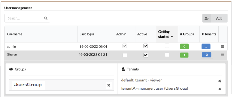
The tab displays the following information about each user:
- Username
- Last login timestamp
- Admin - whether or not the user is sys admin on the VNF Manager (you can check and uncheck this flag to make changes)
- Active - whether or not the user is active (you can check and
- uncheck this field to make changes)
- Getting started -
- # Groups - number of groups the user is a member of
- # Tenants - number of tenants the user is assigned with
To add and manage users
Click Add on the top-right corner of the tab, to create new users. Notice that if you choose to authenticate the users in front of an external user management system, you cannot create or delete the users in VNF Manager, nor can you assign them to VNF Manager user groups, in order to prevent conflicts between the two systems, which causes security problems.
Click a username in the list to reveal associate group and tenant names.
Click
of every user row to do the following: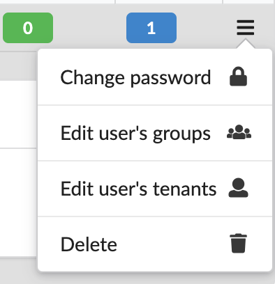
- Change password - use to change the password for the user account.
- Edit user’s groups - use to change associated groups.
- Edit user’s tenant - use to change associated tenants.
- Deleting user - you can only delete users with no associated groups, tenants, or current deployments.
settings
Refresh time interval- The time interval in which the widget’s data will be refreshed, in seconds. Default: 30 seconds.
Role management
A role is a group of permissions that are required by a certain type of user to work in VNFM. You can assign roles to a user to give that user the permissions that are defined in the role. You can also assign roles to user groups to give the permissions that are defined in the role to all of the users in the group. If a user is a member of more than one group, then the user has all of the permissions in the role defined for the user specifically, in addition to all of the permissions defined for all of the roles the user is assigned to via groups.
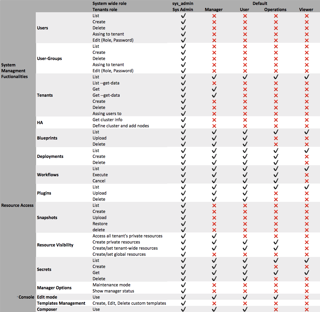
System roles
System roles apply the permissions in the role to the user for all of the tenants, and also for actions outside tenants. Each user must have either:
- sys_admin - This role has all permissions. The admin user is created automatically as sys_admin during the installation process.
- default - This role has no permissions specified.
Tenant roles
Tenant roles apply the permissions in the role to the user or group only in the tenant where the role is assigned to the user or group. You can assign one of these roles to each user or group:
- manager - Can manage all of the private and public resources on the tenant and can create new resources, but cannot create or manage users on the tenant.
- user - Can manage all of the public resources on the tenant and can create new resources.
- operations - Can deploy blueprints and execute workflows, but cannot upload new blueprints or plugins to the tenant.
- viewer - Can view public resources on the tenant.
User Groups
On the System Setup menu, click the Groups tab to display the following information for user groups:
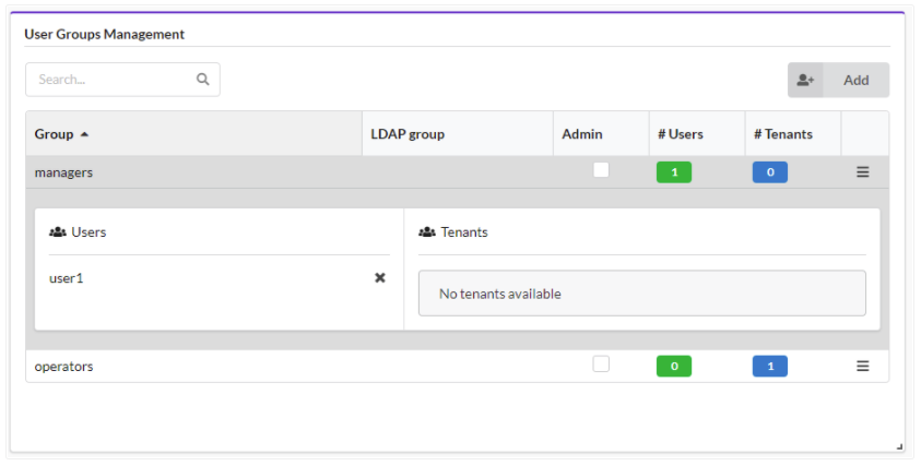
- Name unique name of the group of users.
- LDAP group When working with an ldap-based external authentication system, this field identifies the LDAP user group which is connected to the current VNFM user-group.
- Admin If checked, all users who are members of this groups will have the role of sys-admins on the manager.
- # Users number of users who are members of the group
- # Tenants number of tenants with which the user-group is assigned.
To add and manage groups
Click Add, on the popup screen enter a group name and the associated LDAP group name, select/clear the Admin checkbox to indicate administrative permissions, and then click Add.
Click a Group from the list to view Users and Tenants for the selected group.
Click
in every group row to do the following: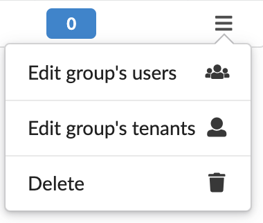
- Edit group’s users - add/remove users to/from the group.
- Edit group’s tenants - add/remove tenants to/from the group.
- Delete group - you can only delete groups with no associated users and tenants assigned to the group.
Tenant management
Displays a list of tenants on the Manager and enables tenant management. This tab is only available to admin users. In the left menu, click System Setup, and then click the Tenant Management tab.
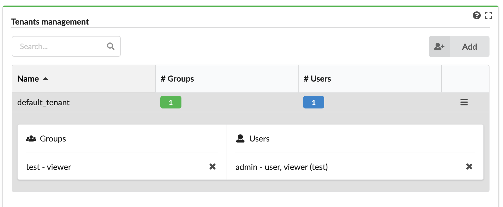
The tab displays the following information about each tenant:
- Name - name of the tenant.
- Number of groups - assigned to the tenant.
- Number of users - directly assigned to the tenant (not as part of groups).
To add and manage tenants
Click Add, enter a name, and then click Add.
Click
in the row of every tenant to do the following: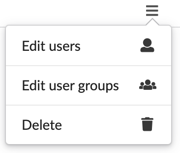
- Add/remove users to/from the tenant
- Add/remove user-groups to/from the tenant
- Delete the tenant - if the tenant has no associated users, user-groups, or resources.
Settings
Refresh time interval- The time interval in which the widget’s data will be refreshed, in seconds. Default: 30 seconds.
System Health
On the left menu expand the System Setup menu, and then select the System Health option.
The System Health menu displays the VNF Manager status divided into the following three services:
- Manager
- Database
- Message Broker
Health services can have the following statuses:
- OK - service type cell background is green
- Degraded - service type cell background is yellow
- Fail - service type cell background is red
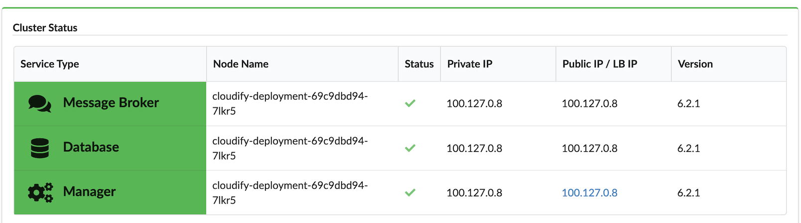
On the System Health menu, verify the following information:
- Node Name
- Status - hover over the status icon to see popup details and copy raw info about node status to the clipboard
- Private IP - Node IP address
- Public IP / Load Balancer IP - in case of Manager node, click the IP to display that node in the VNF Management Console
- Version - Version of VNFM on the selected node
Tip
To quickly view system status, scroll down the left-side menu, click the Health option, and the System Health fly-out menu appears, where you can view the following status information:
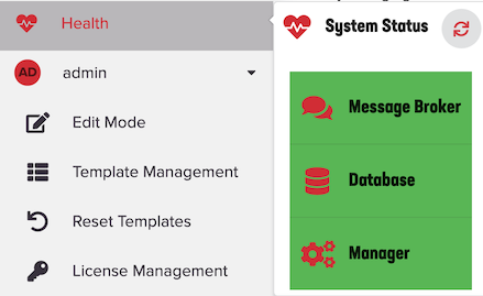
Click
 to refresh the data status displayed on the System Health fly-out menu.
Token management
Select System Setup blade, and then click Tokens to display the list of tokens that you can manage.
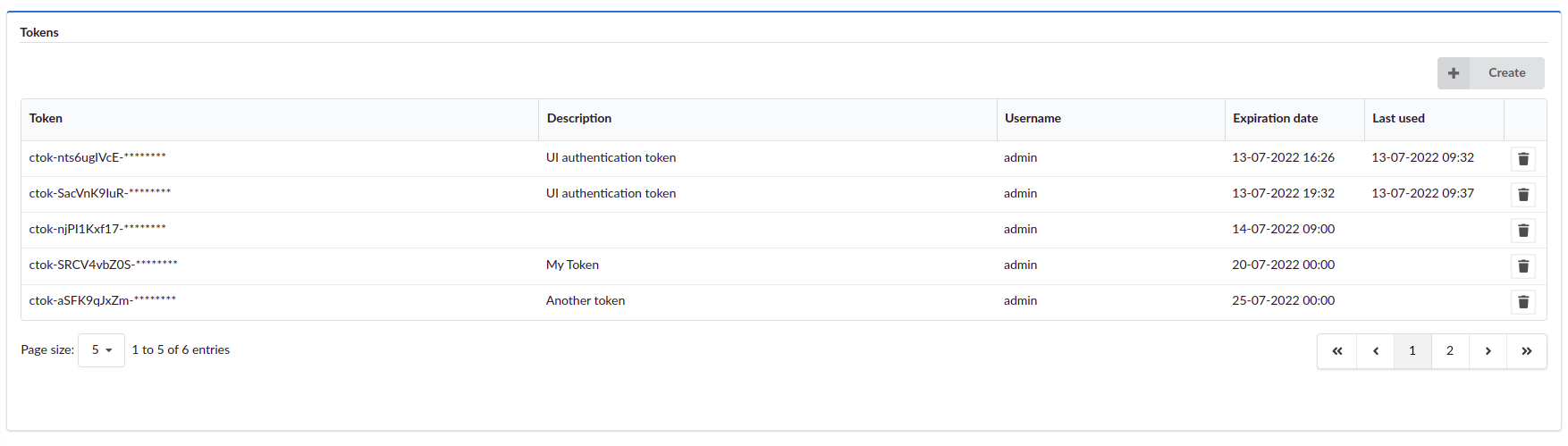
Tokens list
The widget displays the following information about existing tokens:
- Token - Value of the token, masked with asterisks.
- Description - More details about the token.
- Username - Username of the user who created the token (only visible for admin users).
- Expiration date - Date of the token expiration.
- Last used - Date of last token usage.
Creating a token
- Click Create in the Tokens pane.
- OPTIONAL: Provide a description for the token.
- OPTIONAL: Provide an expiration date for the token.
- Click Create.
- OPTIONAL: Show or copy the token value. Once you close the Create token window, you can’t show or copy the token value.
- Click Close.
Deleting a token
- On the far right, click Delete.
- Click Yes.
Settings
- Refresh time interval - Time interval in which the widget’s data is refreshed, in seconds (default value: 10 seconds).
- Show expired tokens - Select to display expired tokens.
System Logs
Click the System Setup blade, and then click the System Log tab displays the Events and Logs pane and filtering drop-down menus.
Events and logs
Displays the logs and events of all the executions in the current tenant, according to set permission levels. You can configure the fields that are displayed and can choose to indicate in colors success and failure messages.
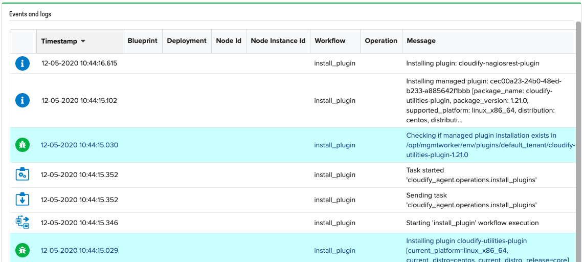
Sometimes error logs can contain additional information about error cause or the event/log message is truncated
(see Maximum message length before truncation setting below), indicated by the ![]() icon in the Message column.
Click on
icon in the Message column.
Click on ![]() to see full message and error causes, if any:
to see full message and error causes, if any:
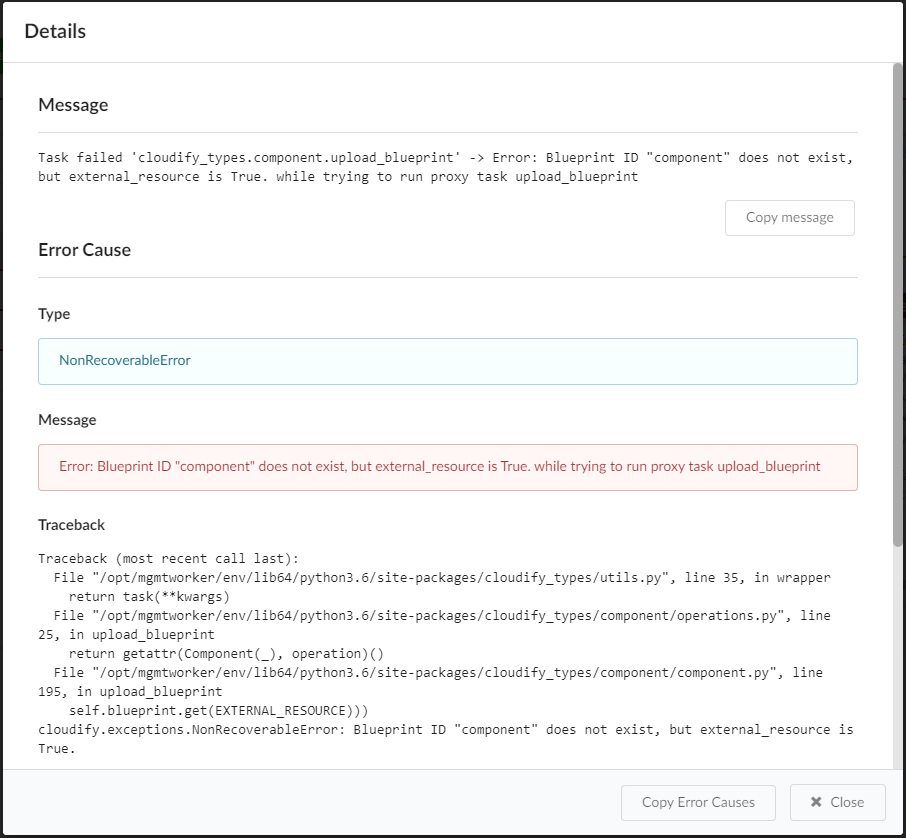
Settings
Refresh time interval- The time interval in which the widget’s data will be refreshed, in seconds. Default setting is 2 secondsList of fields to show in the tableYou can choose which fields to present and sort. By default, these are the fields presented:- Icon
- Timestamp
- Blueprint
- Deployment
- Node Id
- Node Instance ID
- Workflow
- Operation
- Message
- Type
You can also choose to add the field “Type,” which will present the log level in case of a log, and event type in case of an event.
Color message based on type- when marked as “on,” successful events will be colored blue, and failures in red. Default setting is On.Maximum message length before truncation- Allow to define the length of the messages presented in the table. Default limit is 200.
Note
If message is truncated in the table, hover your mouse over the text to read the full message.
To adjust the amount of log files collected in the log viewer
In the VNFM UI, left menu, expand Admin.
Select Edit Mode.
In the Log viewer pane, click Settings
 .
.In the Configure Widget dialog box, increase or increase the Refresh time interval setting, and then click Exit in the Edit mode window.
This will decrease/increase the amount of logs collected in the Log viewer pane.
Filtering options
- Type - Logs/Events
- Event Types - predefined event types include:
- Policy end successfully started
- Policy failed
- Processing trigger
- Task ended successfully
- Task failed
- Task received
- Task rescheduled
- Task retried
- Task sent
- Task started
- Trigger
- failed
- Trigger succeeded
- Workflow cancelled
- Workflow ended successfully
- Workflow event
- Workflow failed
- Workflow
- initializing node
- Workflow initializing policies
- Workflow node event
- Workflow received
- Workflow staged
- Workflow started. You can also specify your log level by typing in text. Multi-selection available.
- Log Levels - predefined log levels: Debug, Info, Warning. Error, Critical. You can also specify your log level by typing in text. Multi-selection available.
- Operation - part of log/event operation
- Message Text - part of log/event message
- Time Range - time range to get log/events
Executions management
In the left-side menu, click the Executions menu, and the default details displayed include the following:
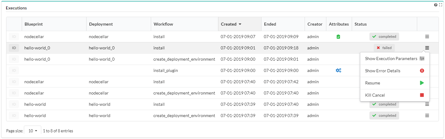
Filters:
- Blueprint drop-down selector - expand to select a deployed blueprint from the list by which to filter and display running executions and associated executions status graphs.
- Deployment drop-down selector - expand to select a running deployment from the list by which to filter and display running executions and associated executions status graphs.
- Execution status - expand to select a running status from the list by which to filter and display running executions and associated executions status graphs.
Running Execution - displays the total number of executions run for the selected blueprint (for example, in one of the following statuses: ‘pending’, ‘started’, ‘cancelling’, ‘force-cancelling’, according to the user’s permissions).
Executions Status Graphs - displays the number of executions per status as a bar chart graph.
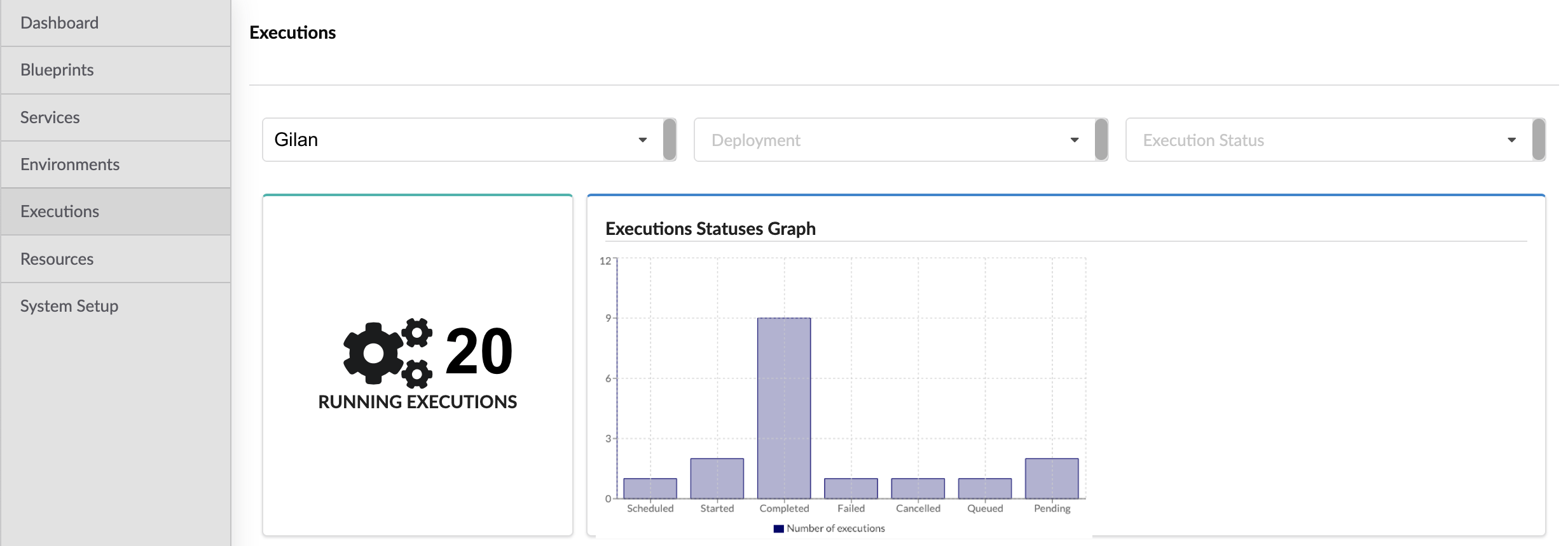
Executions pane - displays the Blueprint name, Deployment name, Workflow name, Created and Ended date/timestamps, Attributes, and Status associated with all currently running workflows.
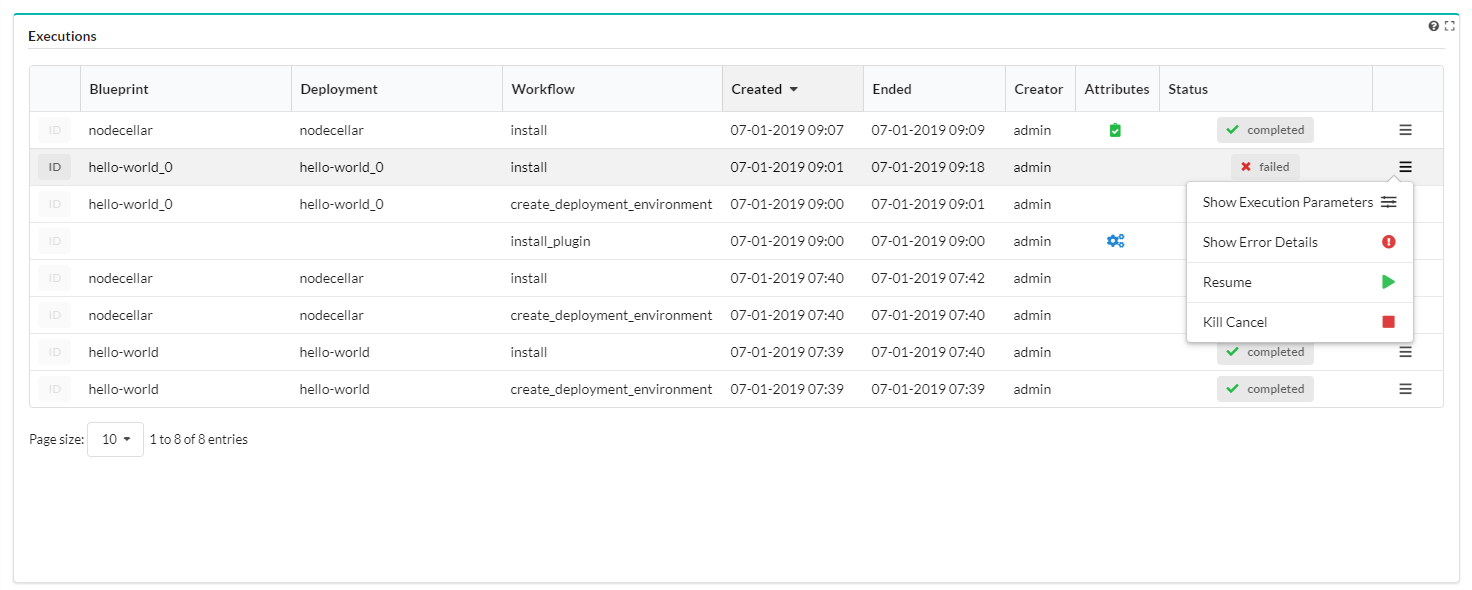
- Attributes column can display the following:
 Dry Run - representing executions set for a Dry Run. Dry-run executions allow you to execute a workflow
so that the entire flow of the execution (all the operations that are executed in an actual run) is shown, but no
actual code is executed and there are no side effects. A dry-run is useful for complex blueprints with potentially
long executions. The dry-run helps you configure relationships between node templates, and operations that depend
on those relationships.
Dry Run - representing executions set for a Dry Run. Dry-run executions allow you to execute a workflow
so that the entire flow of the execution (all the operations that are executed in an actual run) is shown, but no
actual code is executed and there are no side effects. A dry-run is useful for complex blueprints with potentially
long executions. The dry-run helps you configure relationships between node templates, and operations that depend
on those relationships. Service Workflow - representing executions run by built-in system workflows. No other
executions can start while system-wide workflows are running. For example, snapshots create workflow cannot start
while an install workflow is running.
Service Workflow - representing executions run by built-in system workflows. No other
executions can start while system-wide workflows are running. For example, snapshots create workflow cannot start
while an install workflow is running.
- The action menu includes the following, depending on the workflow:
- Show Execution Parameters - shows details in modal window about execution parameters
- Show Update Details - shows details in modal window about blueprint and inputs change (available only for ‘update’ executions)
- Show Error Details - shows error details in modal window (available only for failed executions)
- Resume - resume the execution (available only for cancelled or failed executions)
- Cancel - cancels the execution (available only for active executions)
- Force Cancel - enforces cancellation of the execution (available only for active executions)
- Kill Cancel - the process executing the workflow is forcefully stopped, even if it is stuck or unresponsive
- Attributes column can display the following:
Execution task graph
Workflow defines tasks that can be executed on a node or a group of nodes. Most workflows are implemented with a tasks graph. When the workflow is being executed, the state of the tasks graph, and each operation in it, is persisted to storage. When the workflow is resumed, the tasks graph is reconstructed, and the execution continues.
Visualization modes include Workflow execution task graph, which appears in the Executions widget two ways, depending on the Show most recent execution only parameter value (see the Settings topic for details):
Off - default view (Executions list) - after selecting an execution by clicking its row in the table a corresponding task graph is displayed
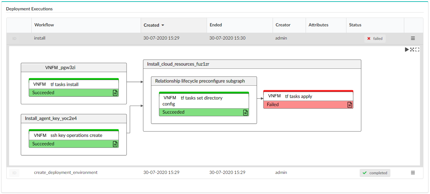
On - single execution view - the last execution for the selected deployment is displayed
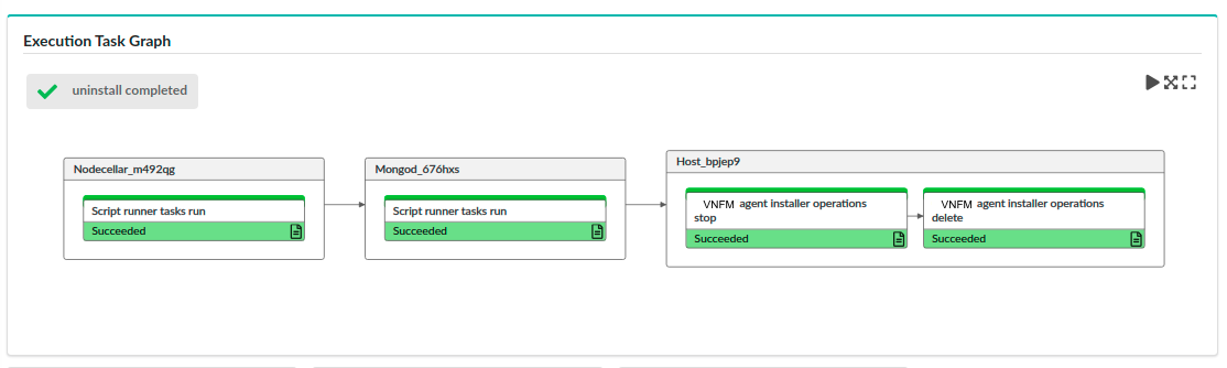
Task state for each graph node represents a task that is part of the execution. Each node is colored depending on task state:
- White - pending
- Yellow - executing
- Green - completed
- Red - failed
Click  in the top-right corner, to do the following:
- Execute Play mode in which the view tracks the progress by following tasks in progress
- Fit to view to display entire graph inside widget borders
- Open in window to display graph in modal view with miniature view for large workflows
A task node may contain an icon in the bottom-right corner:
It allows you to automatically set an operation in Events/Log Filter widget related to that task and filter logs in Events/Logs widget to display only those which are relevant for the selected task. For more information, see the Events Log topic.
Settings
Settings include the following:
Refresh time interval- The time interval in which the widget’s data will be refreshed, in seconds. Default: 5 secondsList of fields- You can choose which fields to display in the table, in addition to the following default fields:- Blueprint
- Deployment
- Workflow
- Created
- Ended
- Creator
- Attributes
- Status
- Actions
You can also choose to add an ID column from the list, which will present the execution ID. By default this value is not presented as a column in the table, but as a pop-up shown by hovering over ID label.
Show system executions- enabling you to include or exclude executions of system workflows in the list (default setting is On)Show most recent execution only- if enabled the widget only displays a tasks graph for the most recent execution (default setting is Off)
Execution Status Graphs
Displays the number of executions per status as a bar chart graph.
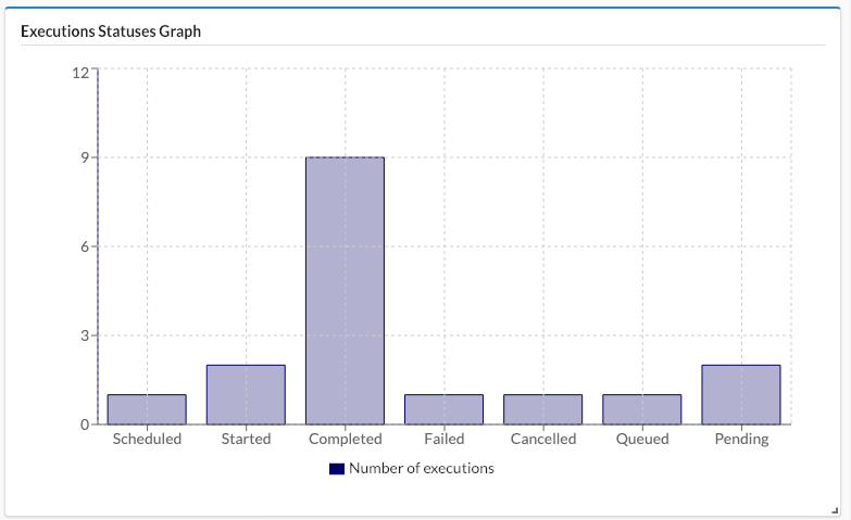
Settings
Refresh time interval - The time interval in which the widget’s data will be refreshed, in seconds. Default setting is 5 seconds.
Snapshots
Click the System Setup blade, and then click the Snapshots tab to display both snapshots created on this manager and uploaded snapshots. Snapshots capture the data of the entire VNF Manager, not just that of a specific tenant. However, the snapshot is created in the context of the current tenant, and therefore must be restored from that tenant.
Note
This tab is only available for Admin users. Snapshots are always created with ![]() private visibility,
which you cannot change.
private visibility,
which you cannot change.
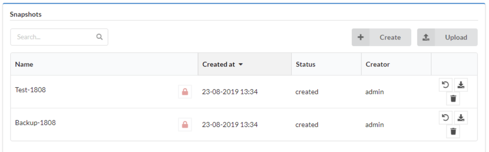
The tab displays the following information for each snapshot:
- ID - the name given to the snapshot upon creation
- Visibility - always “private” for snapshots
- Creation time
- Status - one of: created/creating/failed/uploading/uploaded
- Creator
Manage snapshots
To create snapshots, do one of the following:
Click Create to create a new snapshot on the current tenant, enter a unique Snapshot ID, toggle the following flags to enable/disable, and then click Create:
- Include credentials - capture SSH keys (including those uploaded with blueprints).
- Exclude logs - do not capture logs in the snapshot.
- Exclude events - do not capture events in the snapshot.
- Queue - perform snapshot creation workflow and run automatically when possible.
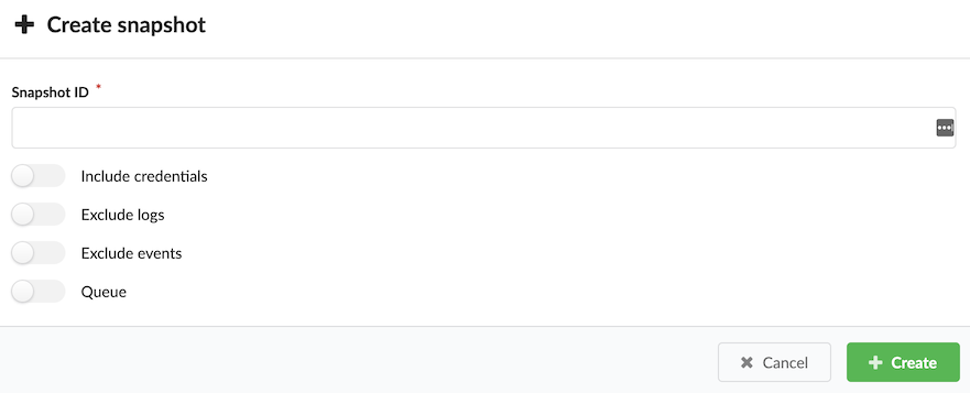
Click Upload, browse for a local file or enter a URL, and then enter a Snapshot name
Note
If there are active executions when you attempt to create the snapshot, the process waits until the executions are complete before creating the snapshot. You can see the status of executions in the Executions menu.
The snapshot is saved as a ZIP file and appears in the Snapshots table, together with details of its creator, creation date and time, and current status.
To manage existing snapshots, in the right column of every snapshot, click the following:
 Restore snapshot - and overwrite existing data appearing in the Snapshots table. If you restore a
snapshot to a VNF Manager instance that already contains data, that data is overwritten; therefore, to prevent unintentionally
overwriting existing data, you MUST enable the force restore data overwrite and delete existing data option.
When restoring from a tenant-less environment, make sure you uploaded the snapshot to a clean (with no resources)
tenant. To restore ignoring plugin failures and other deployment failures due to plugins.
Restore snapshot - and overwrite existing data appearing in the Snapshots table. If you restore a
snapshot to a VNF Manager instance that already contains data, that data is overwritten; therefore, to prevent unintentionally
overwriting existing data, you MUST enable the force restore data overwrite and delete existing data option.
When restoring from a tenant-less environment, make sure you uploaded the snapshot to a clean (with no resources)
tenant. To restore ignoring plugin failures and other deployment failures due to plugins.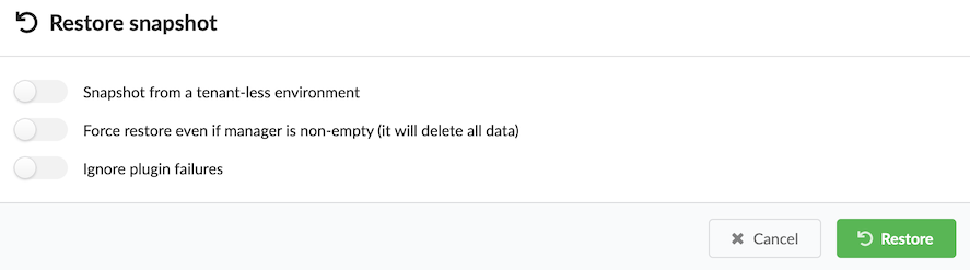
- Download snapshot - and copy a snapshot to your local machine.
- Delete snapshot - and remove snapshot from VNF Manager.
Settings
Refresh time interval - The time interval in which the widget’s data will be refreshed, in seconds. Default: 30 seconds.
Manage Labels
A deployment label is a key-value pair that you can assign to a deployment. You can assign multiple labels with each deployment, and you can assign more than one label with the same key (yet different value) to the same deployment. Use the CLI to create labels to create labels.
Add labels to deployments
Click the Services blade.
Click the deployment for which you want to assign a label, and then click Details.
Click the Deployment Info tab, and then scroll down to the Labels pane.
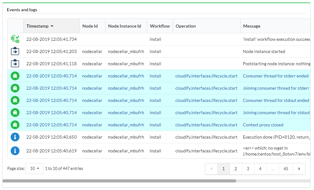
Click Add, at the popup menu expand the dropdown menu to select label(s), and then click Add.
Manage Labels action menu
Click the Services blade.
Click the deployment for which you want to assign a label, and then in the righ-side pane click
Deployment actions.Click Manage Labels from the list.
Add/Remove labels to/from the deployment, and then click Apply.
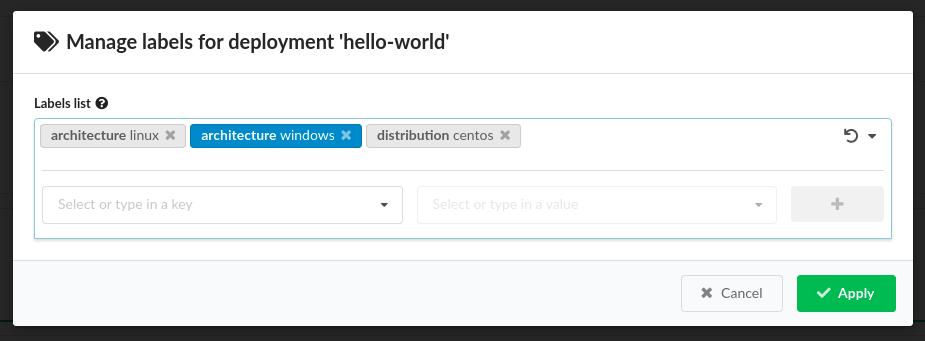
Note
New labels (not existing in the system) appear blue.
LDAP
The vnfm ldap command is used to set LDAP authentication that enables you to integrate your LDAP users and groups with F5 VNFM.
Note
You can use the CLI vnfm declaration in the F5 VNF Manager ONLY.
Optional flags
These commands support the Common CLI flags.
These will work on each command:
-v, --verbose- Show verbose output. You can supply this up to three times (for example, -vvv).-h, --help- Show this message and exit.
Set command
Usage
vnfm LDAP set [OPTIONS]
Set F5 VNF Manager to use the LDAP authenticator.
Required flags
-s, --ldap-server TEXT- The LDAP address against which to authenticate, for example: ldaps://ldap.domain.com.-u, --ldap-username TEXT- The LDAP admin username to be set on the F5 VNF Manager.-p, --ldap-password TEXT- The LDAP admin password to be set on the F5 VNF Manager.-d, --ldap-domain TEXT- The LDAP domain to be used by the server.
Optional flags
-a, --ldap-is-active-directory- Specify whether the LDAP used for authentication is Active-Directory.-e, --ldap-dn-extra TEXT- Additional LDAP DN options.
Example
$ vnfm ldap set -s [LDAP SERVER ADDRESS] -u [LDAP ADMIN USERNAME] -p [LDAP ADMIN PASSWORD] -d [DOMAIN NAME]
Integrate with LDAP
VNFM provides a user management mechanism, so you can define different users with different permissions, and upon login perform authentication and authorization to control the users’ access to resources. If you enable LDAP integration, then you must configure VNFM system role membership using user-groups.
You define and manage the users either in F5 VNFM itself, or you can configure your Manager to integrate with an LDAP-based user-management system. You must select one of these options, as you cannot do both, and you must configure your manager accordingly upon installation or immediately afterwards, when no actions are performed on it yet.
If you enable LDAP with existing users already on the VNF Manager, those users will continue to exist but cannot be used to log in unless they match an LDAP username; for example, if a user jbloggs exists on the VNF Manager before you enable LDAP , then after LDAP is enabled a login is made by LDAP user jbloggs, the LDAP user jbloggs will be shown as the creator of any entities (for example, blueprints, secrets, deployments) that were created by the original jbloggs user.
The initial admin user (default name, admin) is authenticated using local authentication. You can perform user management using the CLI or the VNF Manager console.
Note
For Active Directory, currently only one domain is supported. VNFM does not support logging in using any other domains in a forest.
Tip
User Management Credentials: You must have F5 VNFM administrator permissions to perform user management-related actions.
Basic integration
In order to enable LDAP user integration you must know: The LDAP server address; for example, ldap://192.0.2.1 or ldaps://192.0.2.4.
The domain the LDAP server is associated with; for example, local.example. For active directory, this is used when formatting
the username for authentication (for example, jbloggs will authenticate as jbloggs@local.example). This is also used for the
base DN of lookups, for example, as dc=local,dc=example. If using LDAPS to authenticate over TLS (recommended), then you must provide the
PEM encoded CA certificate.
A basic setup assumes that authenticated users will be able to query the directory for their group membership and that there is no nesting of groups.
Tip
- Basic Active Directory LDAP integration: Assuming no TLS, with a server address of 192.0.2.1, and domain of
ad.example: vnfm ldap set --ldap-server ldap://192.0.2.1 --ldap-domain ad.example --ldap-is-active-directoryorvnf ldap set -s ldap://192.0.2.1 -d ad.example -a. - Basic non-AD LDAP integration: Assuming TLS, with a server address of 192.0.2.4, a domain of slapd.example, and
a CA cert located in
/home/centos/ldapca.crt: vnf ldap set --ldap-server ldaps://192.0.2.4 --ldap-domain slapd.example --ldap-ca-path /home/centos/ldapca.crtorvnf ldap set -s ldaps://192.0.2.4 -d slapd.example -c /home/centos/ldapca.crt
Advanced integration
Defaults for active directory and non-active directory setups are given below. If your settings differ, or you need nested group lookups, consult the following command options to determine the correct settings to supply.
Examples given assume a user attempting to log in as jbloggs and an LDAP domain of local.example.
For details of variables (for example, {username}), see below.
For active directory:
- Base DN for lookups is the domain, split on ‘.’, as a series of dc LDAP entities; for example,
dc=local,dc=example - Users bind as
{username}@{domain}; for example,jbloggs@local.example - Accounts are located by searching with the query (
|(sAMAccountName={username})(uid={username})) - e.g. (|(sAMAccountName=jbloggs)(uid=jbloggs)) - LDAP objects are expected to have the following attributes:
- uid (required)- The username of the user, e.g. jbloggs
- givenName (optional)- The given name of the user- this may be blank. If not blank, it will be stored as part of the user details on the VNF Manager.
- sn (optional)- The surname of the user- this may be blank. If not blank, it will be stored as part of the user details on the VNF Manager.
- email (optional)- The e-mail address of the user- this may be blank. If not blank, it will be stored as part of the user details on the VNF Manager.
- memberOf (required)- If the user is a member of no groups other than their primary group (Domain Users) then they will be effectively unusable with VNFM, so this should be populated with the group membership.
- Groups are looked up by consulting the memberOf attribute on a user (or, with nested lookups, on the groups).
For other directories (for example, openldap):
- Base DN for lookups is the domain, split on ‘.’, as a series of dc LDAP entities; for example,
dc=local,dc=example - Users bind as
uid={username},ou=users,{base_dn}; for example,uid=jbloggs,ou=users,dc=local,dc=example - Accounts are located by searching with the query
(uid={username}); for example,(uid=jbloggs) - Groups which the user is a member of are located by searching with the query
(uniqueMember={object_dn}); for example,(uniqueMember=uid=jbloggs,ou=users,dc=local,dc=example) - LDAP objects are expected to have the following attributes:
- uid (required)- The username of the user; for example, jbloggs
- givenName (optional)- The given name of the user- this may be blank. If not blank, it will be stored as part of the user details on the VNF Manager.
- sn (optional)- The surname of the user- this may be blank. If not blank, it will be stored as part of the user details on the VNF Manager.
- email (optional)- The e-mail address of the user- this may be blank. If not blank, it will be stored as part of the user details on the VNF Manager.
- memberOf (optional)- If groups are present on user objects using this attribute they must also be on group objects if using nested lookups.
- Groups are looked up using either the memberOf attribute (if present), or the group membership lookup query above.
To override the above options, consult the following LDAP set command options:
Variables
Some of the options can accept variables which will be substituted. Such variables are provided enclosed in braces; for example,
{base_dn}. The available variables for each option will be listed in the options below, and all come from the following list:
- {base_dn} - The base DN for all LDAP searches. By default this is the same as the domain DN.
- {domain_dn} - The domain name converted to LDAP format; for example,
local.example becomes dc=local,dc=example`. - {object_dn} - The DN of the object (user or group) that is being checked for membership of groups.
- {username} - The username of the user attempting to bind (for bind format) or the user attempting to log on (for all lookups).
- {domain} - The raw domain; for example,
local.example.
Usage
vnfm ldap set [OPTIONS]
Options
-s, --ldap-server TEXT- The LDAP server address to authenticate against; for example,ldap://192.0.2.1 [required] -d--ldap-domain TEXT- The LDAP domain to be used by the server; for example,local.example [required] -a--ldap-is-active-directory- Specify that the LDAP used for authentication isActive-Directory -c--ldap-ca-path TEXT- Path to the CA certificate for LDAPS communications. Must be provided when using LDAPS, and not when using LDAP.
If the username and password options are used, then use with a minimally privileged account as the credentials are necessarily stored un-hashed in the database. If at all possible, it is recommended that username and password are not set.
-u, --ldap-username TEXT- The LDAP username to bind with for lookups. Only required if standard users cannot look up their user object and groups.-p, --ldap-password TEXT- The LDAP password to bind with for lookups. Only required if standard users cannot look up their user object and groups.--ldap-base-dn TEXT- The base DN for searches, etc.--ldap-group-dn TEXT- The base DN for searching for groups when performing user group lookups. Only used if the group membership is not available on the user object’s group membership attribute. Defaults to ‘ou=groups,{base_dn}‘. Can accept {base_dn} and {domain_dn} variables.--ldap-bind-format TEXT- The format to use when binding to the LDAP server. Defaults depend on active directory setting, see previous. Can accept {username}, {domain}, {domain_dn}, and {base_dn} variables.--ldap-user-filter TEXT- The search filter when searching for the LDAP user. Defaults depend on active directory setting, see previous. Can accept {username}, {domain_dn}, and {base_dn} variables.--ldap-group-member-filter TEXT- The filter used when searching recursively for group membership. Can accept {object_dn}, {username}, {domain_dn}, and {base_dn} variables.--ldap-nested-levels TEXT- How many levels of group membership to check to find the groups the LDAP user is in. If set to 1 (the default), only the groups the user is directly a member of will be available. This setting directly affects the amount of LDAP lookups performed- one extra lookup will be performed if this is increased to 2, for example.--ldap-attribute-email TEXT- The name of the LDAP attribute giving the user’s e-mail address. Defaults to email. If this attribute is missing or empty then no e-mail address will be set for the user in the database.--ldap-attribute-first-name TEXT- The name of the LDAP attribute giving the user’s first name. Defaults to givenName. If this attribute is missing or empty then no first name will be set for the user in the database.--ldap-attribute-last-name TEXT- The name of the LDAP attribute giving the user’s last name. Defaults to sn. If this attribute is missing or empty then no last name will be set for the user in the database.--ldap-attribute-uid TEXT- The name of the LDAP attribute giving the user’s uid. This attribute must not be missing or empty. Defaults to uid.--ldap-attribute-group-membership TEXT- The name of the LDAP attribute giving the user’s group membership. Default value is memberOf. If this attribute is missing, a lookup is performed using the group-member-filter on the group-dn and its subtrees. If this attribute is present but empty, the user cannot be associated with any groups on the VNF Manager.
Example
vnfm ldap set -s ldaps://192.0.2.4 -d slapd.example -c /home/centos/ldapca.crt --ldap-nested-levels 3 --ldap-user-filter '(username={username})' --ldap-group-dn 'ou=departments,o=myorg,{base_dn}' --ldap-attribute-uid username --ldap-bind-format 'username={username},ou=users,{base_dn}'
This will configure the VNF Manager to use LDAP with TLS, binding and performing lookups on server 192.0.2.4. The CA cert
from /home/centos/ldapca.crt is used to validate the server certificate. The slapd.example domain is used, leading to a base DN of dc=slapd,dc=example.
Binding is performed using username={username},ou=users,dc=slapd,dc=example. For example, if the user jbloggs tries to
log in then a bind will be performed as username=jbloggs,ou=users,dc=slapd,dc=example. This bind uses the password jbloggs supplies.
Users are looked up by searching for objects where the username attribute is set to the username being used for login.
Groups will be looked up under ou=departments,o=myorg,dc=slapd,dc=example. The uid for an object is retrieved by consulting
the username attribute on the returned user.
Group lookup is performed up to three levels. For example, if jbloggs is in the Development group, which is in the Technical group and the Research group, both of which are in the IT group. then jbloggs is in the Development, Technical, Research, and IT groups.
Note
These groups are provided with their full LDAP DN; for example, cn=Development,ou=departments,o=myorg,dc=slapd,dc=example.
You must use these DNs when assigning group membership on the VNF Manager.
How F5 VNF Manager works with the LDAP service
When integrating with an LDAP system, F5 VNFM will prevent you to manage users from the Manager, to prevent conflicts between the two systems which can cause security problems. Instead, users will log into F5 VNFM with their LDAP credentials, and the Manager will authenticate them against the LDAP service. To finish the authorization process into F5 VNFM, the users will have to belong (directly, or using nested groups) to an LDAP group connected to one or more F5 VNFM Tenants.
Connect F5 VNFM user-groups with the LDAP groups
To create this connection between the LDAP system and F5 VNFM you must create user-groups in F5 VNFM that represent your LDAP user groups. You then assign those F5 VNFM groups to tenants in F5 VNF Manager, with the desired roles. When a user logs into F5 VNFM, a request is sent to the LDAP system for authentication and identification of the groups to which the user belongs (including groups that contains groups that eventually contains the user - aka nested groups). F5 VNFM then identifies the tenants that the F5 VNFM groups (that represent the LDAP groups) can access, and allows user access according to the permissions the roles of the groups provide. For more information on creating a user group, consult either the CLI command topic, or the Tenant Management topic.
In case a user belongs to multiple groups which are assigned to the same tenant with different roles, the user’s permissions in the tenant will be a sum of all the permission it receives from the different groups. For example, say jbloggs is a member of two Groups in LDAP – “team_leaders”, and “devs”. The team_leaders group is associated in VNFM with the group “all_tenants_viewers”, which is assigned to all of the VNF Manager’s tenants with the role “Viewer”. The “devs” group is associated in VNFM with the group “dev_users”, which is assigned to dev_tenant with the role “User”.
So, jbloggs is now assigned to dev_tenant twice – once as a Viewer and once as a User. Upon logging into this tenant, the permissions jbloggs will have will be a sum of the permissions of the two roles. For more information about user-roles, see Managing Roles. After users have logged in to VNFM, they are visible in the users list, but you cannot perform any management actions on their profiles.
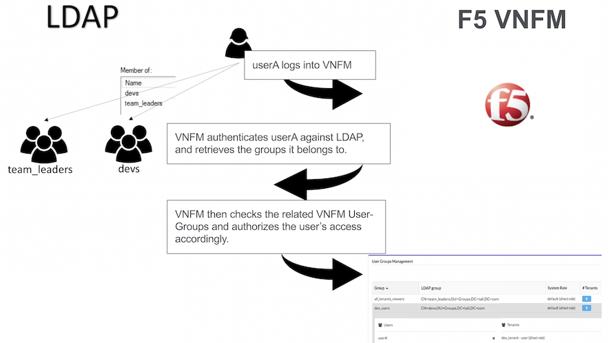
User/LDAP relationship
Tip
- LDAP passwords are not saved in VNF Manager.
- Tokens and LDAP changes to a user’s password on non-LDAP setups will invalidate tokens. When using LDAP, tokens will not be invalidated by password changes, they will only be invalidated by their expiration value (10 hours, or the duration of the associated execution).
Certificates management
In cryptography, a public key certificate, also known as a digital certificate or identity certificate, is an electronic document used to prove the ownership of a public key. The certificate includes information about the key, information about the identity of its owner (called the subject), and the digital signature of an entity that has verified the certificate’s contents (called the issuer). If the signature is valid, and the software examining the certificate trusts the issuer, then it can use that key to communicate securely with the certificate’s subject.
In a typical public-key infrastructure (PKI) scheme, the certificate issuer is a certificate authority (CA), like a company that charges customers to issue certificates for them.
In TLS (an updated replacement for SSL), a server is required to present a certificate as part of the initial connection setup. A client connecting to that server will perform the certification path validation algorithm:
- The subject of the certificate matches the hostname (for example, domain name) to which the client is trying to connect.
- The certificate is signed by a trusted certificate authority (CA).
See Wikipedia for more details.
Cluster certificates setup
The VNF Manager cluster uses the TLS protocol for:
- Communication between the PostgreSQL cluster nodes.
- Communication between the RabbitMQ cluster nodes.
- Communication between the Management service cluster nodes and the other services.
Note
- The certificates/keys are created before proceeding with the installation process and in a PEM format.
- The certificates/keys are copied to
/etc/cloudify/sslduring installation from the source you provide. Therefore, it is up to you to delete the leftovers from the source location. - In case of using externally hosted PostgreSQL or RabbitMQ instances, retrieve the CA must from the hypervisor/VIM service hosting the instance.
- Use the same CA to sign all cluster hosts’ certificates.
The following files must exist on each host:
- CA certificate - The CA certificate that signed the hosts’ public key certificates.
- Public key certificate - A public key certificate signed by the given CA that specifies the host IP and username.
- Private key - The private key associated with the host’s public key certificate.
Use the vnfm_manager generate-test-cert command for creating example certificates.
On a host that has the management service installed, generate certificates for all hosts using:
For a nine-node cluster:
vnfm_manager generate-test-cert -s <manager 1 ip>,<manager 1 hostname>
vnfm_manager generate-test-cert -s <manager 2 ip>,<manager 2 hostname>
vnfm_manager generate-test-cert -s <manager 3 ip>,<manager 3 hostname>
vnfm_manager generate-test-cert -s <postgres server 1 ip>,<postgres 1 hostname>
..
..
vnfm_manager generate-test-cert -s <rabbitmq server 3 ip>,<rabbitmq server 3 hostname>
For a three-node cluster:
vnfm_manager generate-test-cert -s <node 1 ip>,<node 1 hostname>
vnfm_manager generate-test-cert -s <node 2 ip>,<node 2 hostname>
vnfm_manager generate-test-cert -s <node 3 ip>,<node 3 hostname>
Note
Run the previous commands on the same host. For production purposes, use a proper CA (for example, a company CA).
All-in-one Certificates Setup
For an all-in-one VNF Manager, you only need the host’s public key alongside its associated CA certificate and private key.
Replacing certificates
Replacement of the certificates are required as a result of regulatory compliance demand, certificate expiration, or revocation due to security breach. Follow the procedure described in the Replacing Certificates guide when you need to replace certificates.
Manage secure communication certificates
Use the following information to securely manage communication and remote access authorization.
Customize SSL for internal communication
You can override the internal Manager certificate, and the CA
certificate in the F5 VNF Manager configuration. To provide a custom
internal CA certificate for the agents to use, add the
ca_certificate and optionally ca_key inputs, which you must store in the /opt/cloudify/config.yaml file.
To provide a custom internal certificate, use the internal_certificate and internal_key inputs. If none
are provided, F5 VNFM will generate the CA and the internal certificate automatically.
Note
- If provided, the internal certificate must be generated with the appropriate subjectAltName extension to allow connections over every used Manager IP or hostname. The internal certificate must be signed by the CA certificate.
- If the
ca_certificateandca_keyinputs are provided, the internal certificate will be generated and signed using the provided CA. If theca_certificateis provided, butca_keyis NOT provided, then F5 VNFM cannot generate the internal certificate and theinternal_certificateandinternal_keyinputs are required. - In order to use a F5 VNF Manager cluster, the CA key must be present - either generated automatically by F5 VNFM,
or passed in the
ca_keyinput.
SSL mode for external communication
F5 VNF manager, by default, doesn’t use SSL for external communication. You can set the manager to use ssl for the external communication during bootstrap or after bootstrap.
During bootstrap, edit the manager blueprint input. In the
Security Settings section, set ssl_enabled parameter to true, in
order to set the manager ssl mode.
Set the rest_certificate and rest_key parameters, to use your own certificate. If missing, the manager will auto-generate the certificate.
After bootstrap, use vnfm ssl command to enable or disable
the ssl mode. You can also change the manager certificate by replacing
the files under /home/admin/files/ssl/. The relevant files include:
vnfm_external_cert.pem and vnfm_external_key.pem.
When bootstrapping with ssl mode, during the bootstrap the certificate will be copied to the local cli-profile. When using CA signed certificate, you’ll need to update it in the cli-profile (to contain the CA certificate and not the manager certificate) or to remove it (depends on the organization configuration).
In order to update the certificate in the cli-profile, run the following command:
vnfm profile set --rest-certificate CA_CERT_PATH
In case you renew the certificate, just update it in the manager, in the /home/admin/files/ssl directory.
Additional Security Information
- All services required by F5 VNF Manager run under the VNFM (and not root) user in the manager VM. The only exception is the parent process of Nginx, which runs as root in order to enable use of port 80. It is not recommended to change this behavior.
- A secrets store is implemented inside the F5 VNF Manager PostgreSQL database, which provides a tenant-wide variable store.
- Through usage of the secrets store, a user can ensure all secrets (such as credentials to IaaS environments, passwords, and so on) are stored securely and separately from blueprints, and adhere to isolation requirements between different tenants.
- Users need not know the actual values of a secret parameter (such as a password), since they can just point to the secrets store.
- Secrets can be added to the store using a
SETfunction, and retrieved viaGET. - Plugins can access the secrets store, to leverage the secrets when communicating with IaaS environments.
- F5 VNF Manager instances must be secured via SSL to ensure secrets are not passed on an unencrypted communication channel.
- Using PostgreSQL ensures that secrets are replicated across all F5 VNF Manager instances within a cluster, as part of HA.
Deployment Events & Logs
Logs blade in the left-side menu enables you to analyze events/logs produced by your deployments. This menu contains Resource and Time Filter widgets for filtering events/logs listed in Events/Logs widget.
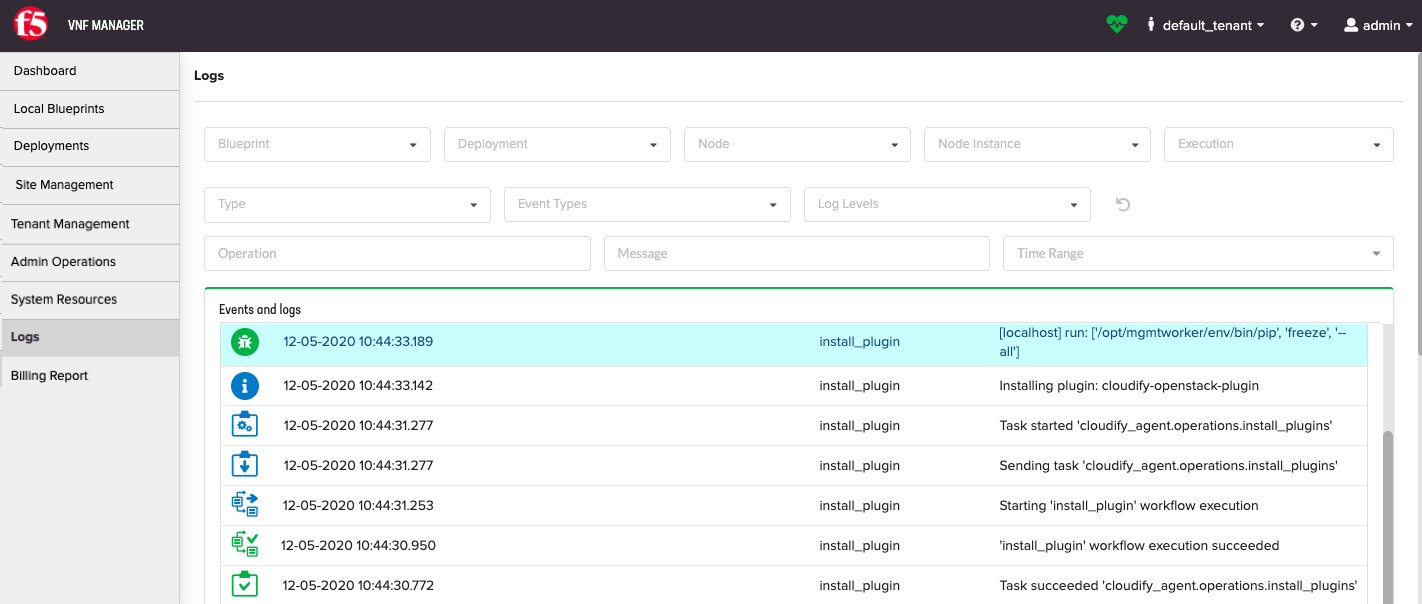
Resource Filter
Resource Filter widget enables you to select a specific execution for logs/events analysis. To limit the list of executions and events/logs, filter by:
- Blueprints
- Deployments
- Nodes
- Node instances
To learn more about using the Resource Filter widget, consult the Resource Filter topic.
Events/Logs Filter
Events/Logs Filter widget enables you to reduce the list of events/logs by specifying log levels, event types, keywords in messages, and time ranges.
To learn more about using the Events/Logs Filter widget, consult the Events/Logs Filter topic.
Resource Filter

Use this widget to filter the data presented in other widgets on the page according to a specific resource. By default, the widget enables filtering by blueprint, deployment, and execution. You can also configuring the widget settings to add fields to filter by node, node instance, and more.
Widget settings
- Refresh time interval - The time interval (in seconds) to refresh the widget data. Default value: 10 seconds.
- Show blueprint filter - To expose filtering by Blueprint. Default value: On
- Show deployment filter - To expose filtering by Deployment. Default value: On
- Show execution filter - To expose filtering by Execution. Default value: On
- Show node filter - To expose filtering by Node. Default value: Off
- Show node instance filter - To expose filtering by Node Instances. Default value: Off
- Show execution status filter - To expose filtering by Execution Status. Default value: Off
- Show site name filter - To expose filtering by Site Name. Default value: Off
- Allow multiple selection - Enables selecting multiple resources in the filter. Default value: Off
Admin
In the left menu, use the Admin blade to access the Edit Mode, License Manager, Change Password, and Log Out of VNFM.
Edit Mode
Use Edit Mode to add/remove existing widgets (panes) to/from UI pages. Widgets are dynamic data units that show up to date information. They are grouped in containers. There are two types of containers: regular widget containers, which are sets of freely arranged widgets, and tab containers, which allow grouping widgets into switchable tabs.
You can select which widgets you want to see on each page, and configure the widgets. Default pages provide views of the most commonly required data. You can delete these pages or add your own.
Edit Mode enables you to create new dashboard pages, add or remove widgets, and manage how widgets are displayed on a page.
Note
If you have a user role, your ability to create dashboard pages and manage widgets depends on the configuration permissions that have been set by the administrator.
Open a page you want to edit.
In the left menu, expand Admin, and then select Edit Mode.
The page you are editing appears with buttons enabling you to add/remove the following:
- Add/Insert Widgets Container
- Add/Insert Tabs Container
- Add Widget
- Add Page
- Add Page Group
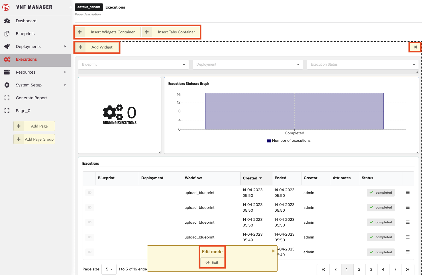
You can do the following:
- Move widgets already on the page by clicking on their title bar and dragging them to the preferred position inside their containers.
- Remove them from the page by clicking the X in the upper right corner of the widget (visible when hovering over the widget’s title bar).
- Open widget configuration window by clicking the Settings icon.
When finished editing, click Exit.
To configure widgets
Some widgets have configuration option that you can define or edit.
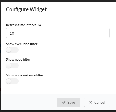
- In Edit Mode, hover over the title bar of the widget you want to configure and click Settings.
- Make your required changes and click Save.
To add built-in widgets
A catalog of built-in widgets is available to enable you to select your preferred data display on any page.
In Edit Mode, choose a desired container (or create a new one) and click Add Widget.
The Add Widget button is visible in all containers when you are in Edit Mode.
Select the widget that you want to add, and then click Add selected widgets. Enter free text in the search box to find a widget.
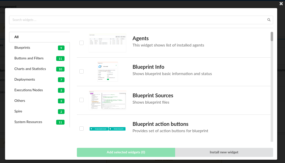
Tip
Click the widget thumbnail to expand to full-sized.
To install custom widgets
In Edit Mode, choose a desired container (or create a new one), and then click Add Widget.
The Add Widget button is visible in all containers when you are in Edit Mode.
Click Install new widget.
Provide URL to widget archive or click
 Browse to select widget archive from your machine,
and then click Install.
Browse to select widget archive from your machine,
and then click Install.Select newly installed widget from the list, and then click Add selected widgets.
To adjust widgets
In Edit Mode, drag and drop widgets in the position that you prefer. To resize a widget, hold the resize arrows in the lower right corner of the widget, and then drag the pane.
To delete widgets
In Edit Mode, to delete a widget, click X in the top-right corner of the widget.
To adjust tab containers
Enter the Edit Mode.
Click Add/Insert Tabs Container.
Every newly created tabs container has two empty tabs.
You can add a new tab with the + icon and remove a tab using the X icon nearby the unwanted tab. You can change the name
of the tab by clicking Edit and completing the form. In that modal window you can also change
the default tab (the default active tab when opening the page).
To add Pages
- In Edit Mode, click Add Page in the sidebar.
- Click the Page title at the top of the page, and then enter a new title for the page. You can also hover over the page name in the
sidebar, and click the Edit to change the name.
- (Optional) Provide a description for the page at the top, below the title.
- (Optional) To set custom icon for the page, expand the page name and select an option from the drop-down menu.
- Add desired widgets for the page.
To add Page Groups
- In Edit Mode, click Add Page Group in the sidebar.
- Hover over the page group name in the sidebar, and then click Edit to change the name.
- (Optional) To set custom icon for the page group, expand the page group name, and select an option from the drop-down menu.
- In the sidebar, click and drag the pages to add/remove them from the group.
License Manager
- Click Admin in the left menu to Edit the VNF Manager license.
- Click End User License Agreement link to read the EULA.
- Click Go to App to return to the VNFM console.
Change Password
To access your VNFM, using https point your browser to the IP address you created in the previous steps and assigned to your management network.
For example, in OpenStack, find your IP address here:
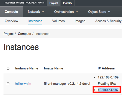
For example, in vSphere ESXi, find your IP address here:
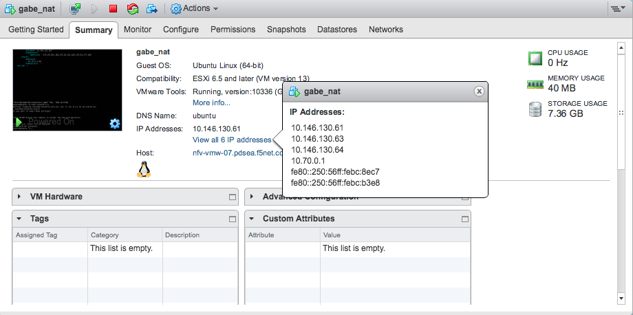
Login to VNFM using username: admin and password: admin.
To change the admin password (you cannot change the username), do one of the following:
To update the admin password using the VNF Manager UI, in the left menu, click Admin, select Change Password, and then in the Change password for Admin dialog box enter a complex password.
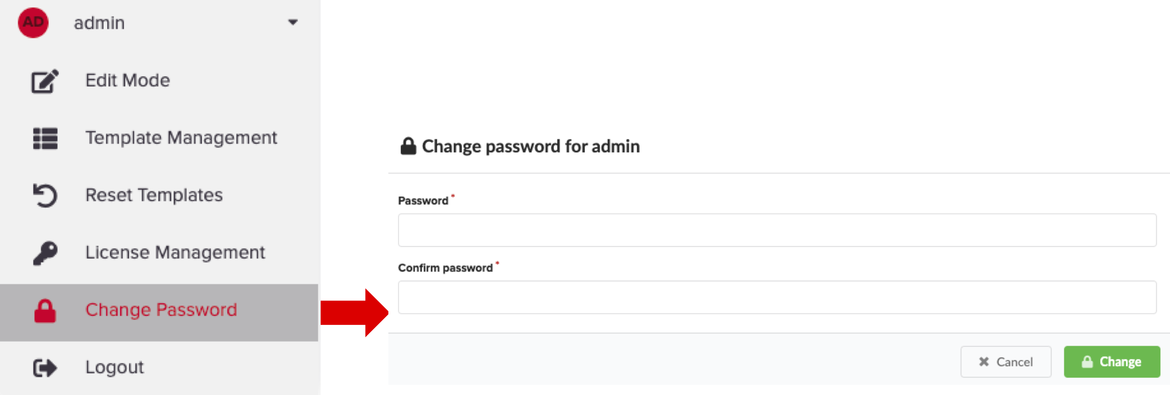
To update the profile using the CLI type:
[admin@vnfm ~]$ vnfm users set-password admin -p new_admin_password.
MANDATORY: To update the admin profile, using the CLI you MUST do the following:
[admin@vnfm ~]$ vnfm profile set -p new_admin_password
Validating credentials...
Credentials validated
Setting password to <new_admin_password>
Settings saved successfully
[admin@vnfm ~]$ vnfm status
Retrieving Manager services status... [ip=localhost]

Services:
+--------------------------------+--------+
|            service             | status |
+--------------------------------+--------+
| VNFM Console                   | Active |
| AMQP-Postgres                  | Active |
| Manager Rest-Service           | Active |
| RabbitMQ                       | Active |
| Webserver                      | Active |
| Management Worker              | Active |
| PostgreSQL                     | Active |
+--------------------------------+--------+
To learn more, consult the User Management topic, the Server Maintenance CLI guide, and the Tenant Management topic.
Important
F5 recommends managing your VNFM administration account using a role-based access control (RBAC) method, such as LDAP or Active Directory. To learn more, consult the integrating with LDAP topic. At a minimum, set a complex admin password.
Maintenance mode
When in maintenance mode, VNF Manager activity is suspended. It rejects all requests, and does not perform any action other than to display the status of the Manager and it’s version, and to execute sub-commands of the maintenance mode.
VNF Manager has three maintenance states, activated, activating, and deactivated. To view the current maintenance state of the Manager, run vnfm maintenance-mode status. The state is also displayed when you run vnfm status (so long as the state is not deactivated).
- Activated - VNF Manager is in maintenance mode. It ignores all requests except for vnfm status, vnfm –version and sub-commands of vnfm maintenance-mode.
- Activating - An intermediate state in which the VNF Manager is not fully in maintenance mode. Only requests that trigger executions are blocked. This state enables active executions to complete and prevents new executions from being started.
- Deactivated - VNF Manager operates normally. No requests are blocked.
Usage and Flow
By default, the maintenance mode state is deactivated.
To activate maintenance mode, run vnfm maintenance-mode activate. VNF Manager either enters the activated or activating state.
To view the current status of the maintenance mode, run vnfm maintenance-mode status.
Following the activation request, if there are no active executions (running, pending, cancelling etc.), maintenance mode is activated. The output of vnfm maintenance-mode status for the activated state is as follows.
Maintenance Mode Status:
Status:      activated
Activated At: <time of activation>
Activation Requested At: <time of activation request>
If there are active executions, the Manager enters the activating state.
Maintenance Mode Status:
Status:      activating
Activation Requested At: <time of activation request>
VNF Manager currently has <number of active executions> running or pending executions. Waiting for them to finish before activating. After all executions have completed, the Manager enters the ‘activated’ state.
Note
Execution Details - If you run the maintenance mode status command in verbose mode, you can view detailed information about the current active executions.
Run vnfm maintenance-mode deactivate to deactivate maintenance mode.
Running Maintenance Mode from the VNF Manager
You can manage maintenance mode by selecting Maintenance Mode in the drop-down menu adjacent to your user name.
What’s Next?