Workflow user guide
Workflows are automation process algorithms. They describe the flow of the automation by determining which tasks to run and when to run these tasks. A task is an operation (implemented by a plugin), or other actions including running arbitrary code. Workflows are written in Python, using a dedicated framework and APIs.
In this guide you will learn:
- How to execute workflows and for what workflows are used.
- Which workflows you can run for which deployment types.
- Which workflows to run for specific scenarios such as:
- Move service layers
- Upgrade BIG-IP VEs for a VNF group
- Post auto-heal process
- Manually trigger Heal or Scale workflow from Nagios
- Promote the secondary BIG-IQ during an HA-pair failover
- Update CGNAT address pool with more IP space
- Attach additional BIG-IP VE syslog configuration file to a deployment
- Deploy BIG-IP VE HA pair in Cloudify 5.05
- Add tmsh/bash commands to existing deployments
- Enable CGNAT after solution deployment
Tip
If using VNF Manager version 2.1 and later, you can deploy your custom blueprints using the F5 Gilan Plugin and workflows. However, F5 will not provide technical support for your custom blueprint(s). It is your responsibility to verify that your custom blueprint is compatible with the F5 Gilan Plugin and workflows.
Execute Install workflows
For the main solution blueprint you deployed, you must run the Install workflow first. Once your blueprint installs, multiple deployments are created automatically. The list of workflows will change and display only applicable workflows that you can run for each deployment/blueprint type.
Click blade, in the list of Services select the main Gilan deployment (for example) , and then click
 Execute workflow.
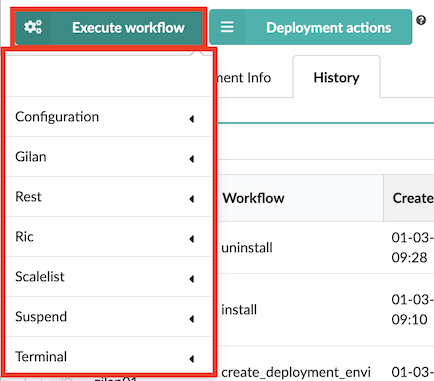
Expand the workflow type options to view applicable workflows you can run, for example, Gilan option (where applicable), select the Install workflow, and then optionally, you can select the following Actions:
- Force - enable this option to force the workflow execution even if other workflows are executing simultaneously. You cannot run this option with Queue enabled.
- Dryrun - enable this option to run this workflow without running any operations. The operations will be logged without side effects. You cannot run this option with Queue enabled.
- Queue - enable this option to run this workflow automatically at the next possible opportunity.
- Schedule - enable this option to run this workflow at a defined date and time (required format, YYY:MM:DD:HH:mm). You cannot run this option with Queue enabled.
Tip
For some workflows, like Uninstall and Heal, you can click
 to upload a YAML file with
execution parameters and complete the form automatically.
to upload a YAML file with
execution parameters and complete the form automatically.Click Execute. Once your install workflow completes, a list of auto-created deployments appears, which have workflows applicable to those deployments. The following sectoions describe ALL the available VNFM workflows; however, this list will change depending upon the deployment node for which you are executing the workflow. You can cancel deployments at anytime by clicking the X in the
 popup workflow notification.
Generate report
Expand the Ric workflow category to run the workflow that creates a
resource-throughput usage report you can send to vesubscriptions@f5.com email address for
billing purposes. Parameters include the values set for these external database parameters (PREVIEW ONLY) and a
boolean true/false value for the full_historical_report that when set to true will generate a full report
(generating data beyond the default of the previous 180 days).
Run this workflow for the following deployment types:
- Gi-LAN
- Gi-Firewall
- DNS
- DNS Security
- VNF Service
- CGNAT Offering
Heal
The Heal workflow determines the resource status with the check status operation. If the Heal option is available, VNFM will heal the resource instead of destroying and recreating that resource.
Healing failing DAG instances, secondary (follower) instances, primary instances, and entire layers, by creating a new copy of the reported, dysfunctional instance or layer without dropping existing traffic (or packets). If you enabled CGNAT, the heal layer workflow will also check the address list of the previous (failing) device, merge with the F5 BIG-IP AS3 configuration, and then send the configuration to the new device in the layer. This workflow will create a new copy of the reported, dysfunctional instance on CGNAT layer.
Note
The new copy of CGNAT instance will have the same cgnat_ip_list as the corrupted instance.
To recover resources from the dysfunctional DAG layer, run the post auto-heal process, which
will release the original resources (for example, CPUs, memory, and disk space).
Run this workflow for the following deployment types:
- DAG
- DNS
- secondary (follower)
- layer instances
- vnfd_cgnat_offering_ve
Install
This workflow installs the target deployment, and lifecycle operations on instances (for example, create and configure start).
Run this workflow for ALL deployment types.
Uninstall
This workflow uninstalls the target deployment, freeing allocated resources, and performing uninstall lifecycle operations (for example, stop and delete). This workflow also removes deployments and blueprints created during the install workflow. Parameter includes ignore_failure, which passes the workflow upon a failed lifecycle operation.
Run this workflow for ALL deployment types.
Delete
After you have uninstalled an application, you can delete it from VNF Manager. After you uninstall an application,
all of its static and runtime properties are still stored in the database and the deployment-specific agents continue
to consume resources. Deleting a deployment enables you to clean the environment of those excess artifacts.
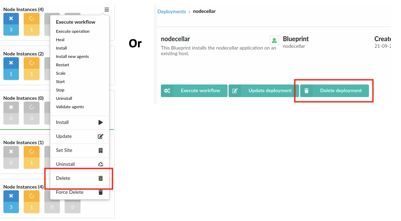
Open the Deployments page, select a deployment from the list, click  ,
and then click Delete. Or, open the Deployments page, click the applicable deployment and on
deployment drill-down page, click Delete deployment.
,
and then click Delete. Or, open the Deployments page, click the applicable deployment and on
deployment drill-down page, click Delete deployment.
Run this workflow for ALL deployment types.
Force Delete
After you have uninstalled an application, you can force delete it from VNF Manager even if it contains active node.
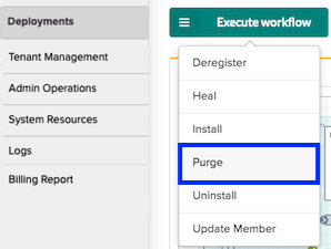
Purge
This workflow Uninstalls and removes dysfunctional secondary and primary VNF, CGNAT layer instances, VNF VE instances, and DNS DAG instances. Start this workflow manually, after the heal layer workflow runs and the problem investigation is finished. Parameter includes ignore failure passed to lifecycle uninstall process (consult the following Uninstall workflow).
Run this workflow for the following deployment types:
- VNF_layer
- DNS_layer
- dns_security_layer
- VNF
- vnfd_dag instances
Scale In
This workflow Removing and uninstalling DAG group, adding VEs and the VNF group, adding layers. This workflow finds instances to remove (based on parameters) and uninstalls and removes all specified instances and all related instances. Parameters include:
- instance ids-JSON encoded list of strings. Each string represents an instance ID, and functions include uninstall and remove instance IDs, and related instances.
- deployment ids-JSON encoded list of DAG VE and VNF layer deployment IDs to remove. For example, [“dep1”, “dep2”].
- ignore failure-boolean value passed to the lifecycle uninstall process (consult the following Uninstall workflow). If true, then a failed task during the uninstall of an instance will be ignored, and the execution will continue.
- ignore_not_found-boolean value passed to the lifecycle uninstall process (consult the following Uninstall workflow). If true, then the execution will ignore instance IDs and deployment IDs that it cannot find.
- ignore_limit-boolean value when set to true, the workflow ignores the instance number limit.
Failed execution can have already, partially remove some resources from external systems and remove instances. In this case, execute the workflow again with ignore_failure flag set to true. You must check the VIM and other external systems for leftover, reserved resources.
Run this workflow for the following deployment types:
Layers
- vnf_layer
- dns_layer
- dns_security_layer
Groups
- vnf_group
- dag_group
- cgnat_offering_group
- dns_group
- dns_security_group
Scale Out
This workflow adds layer instances to DAG and VNF Layer and Group deployment types, and includes defining the add instances parameter, which is the number of new instance VEs to create:
Layers - when creating and installing secondary nodes to new VNF layer the add instances value is the number of managed, VNF secondary VEs to add to the target deployment:
- vnf_layer
- dns_layer
- dns_security_layer
Groups - the add_instances value is the number of new layers you want to add to the group:
- vnf_group
- dag_group
- dns_group
- dns_security_group
Tip
If failure occurs due to scaling limits, this does not affect the service. Other failed executions can be a result of resources already reserved to create instances. In this case, remove the failed instance by running the Gilan Scale In Group workflow [gilan_scale_in_group] and providing the failed (instance id)[instances].
For the following cgnat_offering_layer types, this workflow will add layer instances to the CGNAT layer. If run manually,
you can define how many instances to add to the layer. All instances are installed simultaneously, and instances are not
waiting for each other. The number of CGNAT instances on the layer appears in the cgnat_instance_count output value
(found in the Deployments Outputs/Capabilities pane).
Run this workflow for the following deployment types:
- CGNAT_layer
- cgnat_offering_layer
Analyze the Deployment Outputs/Capabilities data for the automated scale-out of layers
Use the Deployment Outputs/Capabilities pane to understand how the Nagios server automatically scales out resources for your CGNAT Offering blueprint, and which values VNFM uses to calculate your resource usage. This example uses a purchased 10 Gb layer (10000 Mb).
Click the Deployment blade, and then in the deployment list click the nagios server deployment for the primary CGNAT Offering deployment to open it.
Expand the Deployment Outputs/Capabilities pane. This pane displays the number of nodes instantiated when the solution scales out.
To view the original input value you assigned to the CGNAT Offering, in the
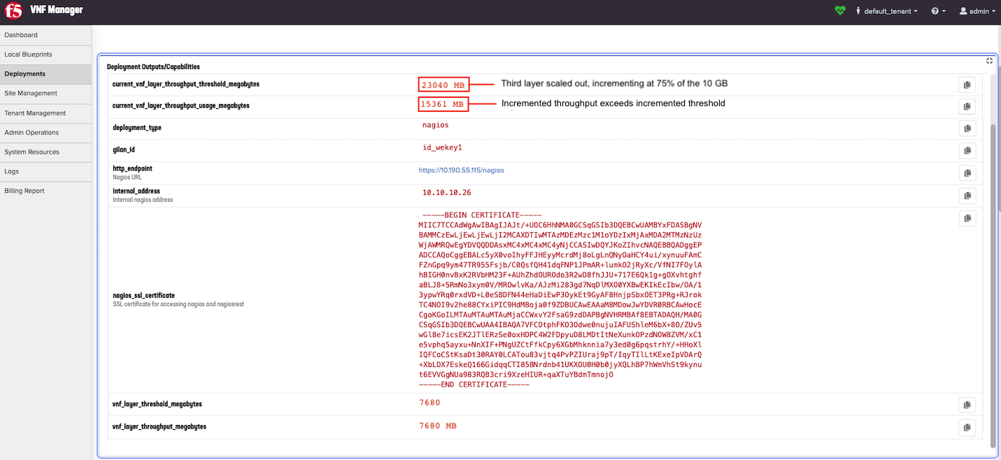
vnf_layer_thresholdinput, scroll to the bottom of the Deployment Outputs/Capabilities pane. The values in the following screenshot represent an example of 75% threshold setting (7500 Mb) of a 10 Gb layer (10000 Mb).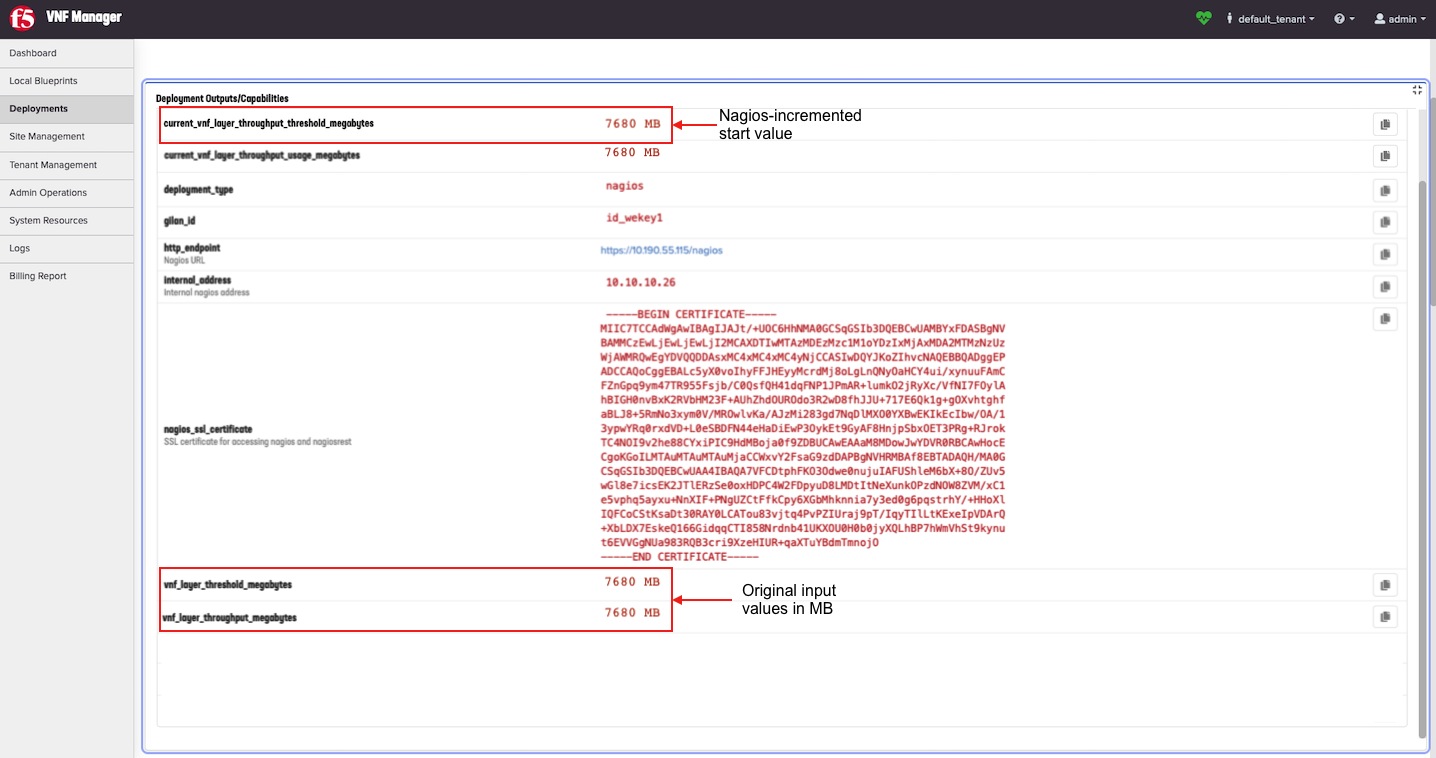
The vnf_layer_throughput_threshold_megabytes value in Mb is the input value you defined in the
vnf_layer_thresholdinput as a percentage of layer throughput. For example, if you used 75% then the value in MB is 7500 Mb. Therefore, Nagios will scale out a second layer when your resource consumption EXCEEDS 7500 Mb.Important
If you exhaust the CPU or RAM usage BEFORE the maximum throughput (7500 Mb) is reached, then VNFM will add another BIG-IP VE to the existing layer. If, the 7500 Mb threshold is reached BEFORE CPU/RAM exhaustion, then VNFM will add another layer of instances. VNFM uses the number of layers to calculate resource usage.
To view the current values that Nagios changes or increments upon automatically running the scale out workflow, scroll to the top of the Deployment Outputs/Capabilities pane. For example, the
current_vnf_layer_throughput_threshold_megabytesis 7500 Mb at the start. However, once Nagios executes the Scale Out workflow, you will have two layers, then this value will increment (or double in size) resulting in 15000 Mb.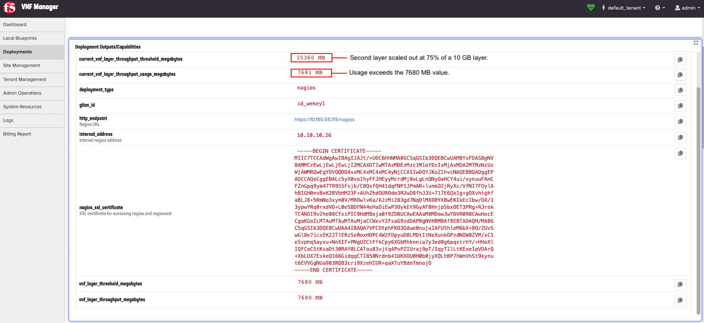
When scaled out again, adding a third layer, this value increments another 7500 mb, resulting in 22500 Mb. Notice that this value scales at a 75% rate of a 10 Gb layer:
Update declaration
Updating the new JSON-encoded and/or YAML-encoded F5 BIG-IP AS3 declaration, Telemetry declaration, or syslog configuration pushed to the VE as a part of NSD definition. Run this workflow after editing any of those declarations in your NSD definition and uploading your changed, primary-solution, blueprint inputs file.
Run this workflow for the following deployment types:
- VNF_NSD
- NSD_DNS
- NSD_SEC_DNS
Upgrade
Enabling the roll-out of a new version of BIG IP in the DNS group, DAG group, CGNAT group, and VNF group. Creating new DNS/DAG/VNF/CGNAT groups of VEs using new software reference data. Workflow selects older VEs with lesser revision value and disables them. Parameter includes instance count, which is the number of instances (DNS VEs) to upgrade.
Run this workflow for the following deployment types:
- All dag_groups
- dns_groups
- dns_security_groups
- CGNAT_group (both CGNAT-Offering and Gi-LAN/F enabled with CGNAT)
- All vnf_groups
Upgrade Start
Starting the upgrade process and setting new software reference data for both DAG group, CGNAT group, and VNF group. You must provide the revision number and software reference details (image id, flavor) for the hypervisor. The revision number is used during the VNF Layer upgrade process. Parameters include JSON encoded dictionary containing definition of new software:
- image-for new BIG-IP (for example, BIGIP-13.1.0.7-0.0.1.ALL_1SLOT)
- flavor-for new BIG IP (for example, f5_small)
- revision-revision number that is incremented with every upgrade. Instances with revision values lower than the number of the upgrade image provided, is considered as using an old version of the software.
Example: {"data":{"image":"BIGIP-13.1.0.7-0.0.1.ALL_1SLOT","flavor":"f5.cloudify_small"}}
Run this workflow for the following deployment types:
- vnf_group
- dns_dag_group
- dns_group
- dag_group
- CGNAT_group (both CGNAT-Offering and Gi-LAN/F enabled with CGNAT)
- dns_security_group
Upgrade Finish
Finishing the upgrade process for DAG group, CGNAT group, and VNF group, using the new software reference data to install scaled and healed VEs, as well as other normal operations. Parameter includes ignore_revision_check a boolean value that when set to true, will ignore the revision values assigned to running instances.
Run this workflow for the following deployment types:
- vnf_group
- dns_dag_group
- dns_group
- dag_group
- dns_security_group
- CGNAT_group (both CGNAT-Offering and Gi-LAN/F enabled with CGNAT)
Admin state disable
Executing this manually on a VNF layer you want to eventually deprecate. This workflow stops new traffic connections (bleeds traffic) on a layer and diverts that traffic to other layers in the data center. For example, you run this workflow in conjunction with the Scale Out and Scale workflows when moving service layers from one data center to another.
Run this workflow for the following deployment types:
- VNF_layer
- dns_layer
- dns_security_layer
Update member
Updating the DAG pool membership of a secondary during a heal workflow. Parameters include:
- adminState - the admin state value of the member being updated. Options include: enable, disable, and offline.
- enable - the enable value for the member being updated. Options include: true or false.
- servicePort - the service port number assigned to the member being updated.
For example, to disable a member, set adminState to disable, enable to false, and servicePort to 0.
Run this workflow for the following deployment types:
- VNFD_VNF
- DNS
- DNS_Security
Deregister
Executing on a secondary node to remove it from the DAG group and manually fail over the traffic to another DAG group. Deregister workflow causes the CGNAT VE to stop listening on 0.0.0.0; however, the machine is NOT turned off, but rather will not process traffic. The Deregistered status will appear in the Deployment Outputs and logs. If you run this workflow repeatedly, you will get a message stating the VE is already deregistered. This workflow is an automated process in the Heal and Upgrade workflows.
Run this workflow for the following deployment types:
- VNF_slave
- DNS_slave
- DNS_security_slave
- vnfd_cgnat_offering_ve
Register
Executing the register workflow causes CGNAT VE to start listening on 0.0.0.0. However it will not start this machine, but it will enable the machine to process traffic. The Registered status will appear in Deployment Outputs and logs. If you run this workflow repeatedly, you will get a message stating the VE is already registered.
Run this workflow for the vnfd_cgnat_offering_ve deployment type ONLY.
Promote
Executing on the BIG-IQ configuration deployment to promote the secondary BIG-IQ in an HA pair, when the primary BIG-IQ fails. Currently, if your VNFM fails to license a BIG-IP, VNFM will display a failure. You must run this workflow manually to promote the secondary BIG-IQ to take over for the failed, primary BIG-IQ.
Run this workflow for the BIG-IQ deployment type ONLY.
Increment IPs (proxy)
Loading more IP addresses on the appropriate VNF/DNS/NSD VE, or execute Increment IPs Proxy. The workflow will add more IP addresses on the appropriate CGNAT VE. This workflow requires no defined parameters. Execute this workflow to increment the IP addresses in the allotment you defined in the inputs file (increment_ip_number). After this workflow, cgnat_ip_list will update in Deployment Outputs, which stores the currently used list by CGNAT VE. You cannot start this workflow for nsd_cgnat_offering nodes manually, it only runs automatically, as manual startup is blocked.
Run this workflow for the following deployment types:
- VNFD
- DNS
- DNS_Security
- NSD deployments
- vnfd_cgnat_offering_ve
- nsd_cgnat_offering
Enable cgnat
Executing on the primary deployment or executing the Enable cgnat on a single nsd deployment when you have NOT enabled CGNAT prior to installing your blueprint solution. IMPORTANT: You must first edit your BIG-IP AS3 declaration (policyNAT) for enabling CGNAT, execute the Update as 3 workflow, before executing the Enable CGNAT workflow, and defining the following parameters:
- increment_ip_number - Value by which your IP addresses are added to your deployment, when you run the Increment IP workflow. Default value is 2.
- ip_ranges_list - IP address range in JSON format for each address list (for example, ‘192.168.1.100-192.168.1.150’ and ‘192.168.1.155-192.168.1.160’)
- starting_ip_number - Number of IP addresses initially assigned to each VNF VE. Default value is 5.
- cgnat_resource_id - Reference/pointer to your NAT source translation pool that you want VNFM to manage and that you defined in your BIG-IP AS3 declaration (policyNAT). For example, “/Sample_22/A1/”.
Run this workflow for the following deployment types:
- Gi-LAN
- Gi-Firewall
- NSD_VNF
Update cgnat IPs
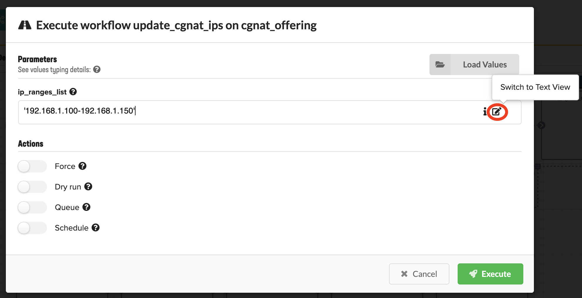
Adding more free IP addresses to the CGNAT. Parameters include the list of IP ranges using JSON format; for example, ‘192.168.1.100-192.168.1.150’ If IP addresses are already in use, the workflow will fail with a duplicate key value error message. If the IP addresses are entered incorrectly, the workflow will fail with an invalid range format error message. In the ip_range_list text box, click Switch to Text View, and then enter the IP range using the required format.
Run this workflow for the following deployment types:
- Gi-LAN with CGNAT enabled
- Gi-Firewall with CGNAT enabled
- CGNAT-Offering
Update
Use this workflow to update the deployment input values for an existing blueprint deployment. You must uninstall and reinstall the blueprint deployment after changing inputs for that deployment. You can set Actions to take upon this updated deployment automatically, like enabling/disabling the auto-running of Install/Uninstall workflows on this specific node instance. You can set to auto-run the Install workflow first. You can enable/disable ignoring failures during the Uninstall workflow, and enable/disable the auto-running of Reinstall workflow.
Run this workflow for the following deployment types:
- Gi-LAN, Gi-Firewall
- DNS, DNS_Security
- CGNAT-Offering
Workflow scenarios
The following scenarios are examples of manually running specific workflows to achieve specific outcomes.
Update a deployment
You can update the BIG-IP AS3 declaration and inputs for existing deployments using the Update option in the menu.
Consult the Update deployments topic in the Deployment maintenance guide.
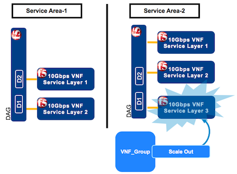
Move a layer to a new data center
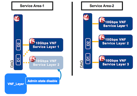
In this example, a telco has two service areas (SA-1 and SA-2). Service demand has dictated that SA-2 requires more capacity than SA-1. The telco has purchased two 10Gb-layers in each SA (layers 1 and layers 2) for a total of four layers. Therefore, in order to increase capacity in one SA-2, first stand up a new (temporary) layer in SA-2, and then bring down a service layer in SA-1. F5 VNFM enables customers to have more layers than originally purchased for a 48-hour grace period. Therefore, this capacity move to a new SA must occur within 48 hours to avoid being charged for the fifth (in this example), additional (temporary) layer in SA-2.
To move a layer from SA-1 to SA-2, manually run the following workflows:
- Scale Out (SA-2)
- Admin state disable (SA-1)
- Scale In (SA-1)
In VNF Manager for the SA-2 where capacity requirements increase, click the Deployments blade, click the VNF Group deployment (for example, vnf_group), at the top of the window click Execute workflow, and then select Scale Out from the list.
On the Execute workflow scale_out popup window, in the add_instances text box, enter the number of new instances you want to add to this group. Default value is 1.
The scale out workflow stands up a new (fifth) layer in SA-2 where capacity demand has increased.
Currently, you have five layers. 48 hours before bringing down a layer in SA-1, click the Deployments blade, click the VNF_layer deployment to bring down (layer 2), at the top of the window click Execute workflow, and then select Admin state disable from the list.
This workflow bleeds new traffic from the VNF layer 2, preventing all new traffic connections, and diverts all new traffic to layer 1 in SA-1. Keep this layer in Admin state disable for approximately 40 hours, allowing all existing connections on layer 2 to finish before bringing down that layer.
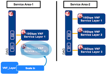
Near the 48-hour threshold, in SA-1, click the Deployments blade, click the VNF_layer deployment to bring down (layer 2), at the top of the window click Execute workflow, and then select Scale In from the list.
On the Execute workflow scale_in popup window, to assign a specific layer or secondary, in the deployment_id text box, enter the deployment ID for the VNF layer/secondary you are scaling-in, and leave all other default values. You can find this deployment ID at the top of the VNF layer/secondary deployment page:
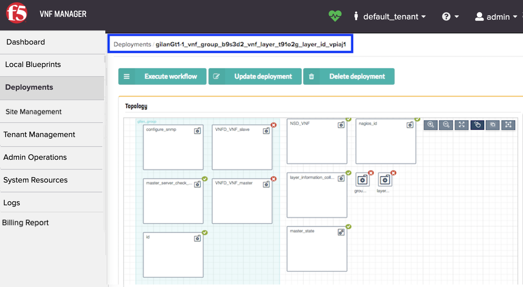
This workflow destroys layer 2 in data center-1 where the capacity need has decreased. Now you have one layer in data center-1 and three layers in data center-2, returning to your originally purchased, four-layer capacity.
Important
To avoid purchasing more capacity than your original purchase, coordinate the timing of your layer deprecation, so your additional (fifth) layer in SA-2 (in step 1) does NOT exceed the 48-hour grace period.
Upgrade BIG-IP VEs in a VNF group
Consult the following video to help you upgrade your BIG-IP VEs. Be aware that the version of VNFM used in this video may not match the version you are currently using; however, the steps are the same.
You can upgrade both VNF and DAG groups. In this example, you will upgrade your BIG-IPs in your VNF group from version BIGIP-13.1.0.5 to version BIGIP-13.1.0.7. Manually upgrading involves executing the following workflows:
- Upgrade Start
- Upgrade
- Admin state disable
- Scale in
- Upgrade Finish

Important
PREREQUISITES:
In your VIM project (for example, OpenStack), you must upload the new BIG-IP image (for example, BIGIP-13.1.0.7) to which you are upgrading PRIOR to performing this workflow scenario. For supported versions of BIG-IP VE, point your browser to BIG-IP 13.1.0.X, BIG-IP 14.1.4.6.ALL_1SLOT, or BIG-IP 15.1.5.1.ALL_1SLOT F5 downloads site.
This upgrade process makes a copy of the VNF group being upgraded (including all layers); therefore, you must have sufficient vCPU and storage capacity to temporarily sustain two VNF groups. Otherwise, your upgrade workflow will fail.
Tip
If you lack the required resources in the service area being upgraded, you can utilize the 48-hour grace period for deploying extra layers and avoid failure by temporarily scaling out layers in another service area, and then scaling in layers in the VNF group being upgraded. After the upgrade completes, you can redistribute the VNF layers amongst the service areas, accordingly. See the previous workflow scenario for complete steps.
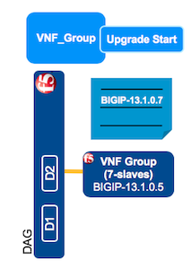
In VNF Manager, click the Deployments blade, click the VNF_group deployment you want to upgrade, at the top of the window click Execute workflow, and then click Upgrade Start.
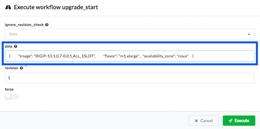
On the Execute workflow upgrade_start popup window, in the data text box, enter the dictionary parameters (in JSON format) for the VNF group you want to upgrade using the image ID for the new image to which you want to upgrade (for example, BIGIP-13.1.0.7-0.0.1.ALL_1SLOT). The image value is case-sensitive and must match the image name as entered in your VIM project.
You can find this dictionary in YAML format in your inputs file, for example in OpenStack:
sw_ref_vnf:
  data:
      image: BIGIP-13.1.0.7-0.0.1.ALL_1SLOT
      flavor: m1.xlarge
      availability_zone: nova
Convert the previous YAML dictionary to JSON format, for example:
{ "image": "BIGIP-13.1.0.7-0.0.1.ALL_1SLOT", "flavor":"m1.xlarge", "availability_zone":"nova" }
In the revision text box, increment that value by at least 1, leave all other default values, and then click Execute.
This workflow defines the image which to upgrade the selected group. To verify the status of this workflow, click the VNF_group deployment, and scroll down to the Deployment Executions pane and in the Upgrade Start workflow row, the status column should display, Complete.
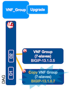
In VNF Manager, click the Deployments blade, click the VNF_group deployment you want to upgrade, at the top of the window click Execute workflow, and then click Upgrade.
On the Execute workflow upgrade popup window, in the deployment_id text box enter the deployment ID of the layer you want to upgrade. To find the layer ID, on the Deployments blade, click the VNF_layer being upgraded and at the top of the page, copy the ID.
This workflow creates a copy of the group and all layers within that group, running the new version of the BIG-IP image defined in step 2. To verify the status of this workflow, click the VNF_group deployment, and scroll down to the Deployment Executions pane and in the Upgrade workflow row, the status column should display, Complete.
Important
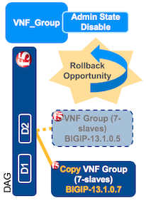
At this point you will want to leave both VNF layers running, to verify that the upgraded copy is running successfully. The duration will vary depending upon your organization’s standard operating procedures. If you experience problems with the upgraded layer, you can rollback the upgrade by running the Admin state disable workflow (consult next step) on the new, upgraded copy of the VNF layer.
In VNF Manager, click the Deployments blade, click the VNF_layer you are upgrading, at the top of the window click Execute workflow, and then click Admin state disable.
Tip
To find the layer ID of the old layer you are scaling in, click the Deployments blade, click the VNF_group being upgraded, scroll down to the Nodes pane, click the layer_id row, and the old layer will appear first in the list. Using the first layer ID in the list, on the Deployments blade search for the layer ID. Click that layer and at the top of the window, copy that ID.
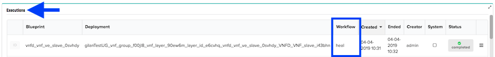
This workflow bleeds new traffic off the older VNF group being upgraded and moves new traffic to the newly upgraded copy of the VNF group. Allow enough time for existing transactions to complete, before executing the Scale In workflow (step 7). To verify the status of this workflow, click the VNF_layer deployment, and scroll down to the Deployment Executions pane and in the Admin state disabled workflow row, the status column should display, Complete.
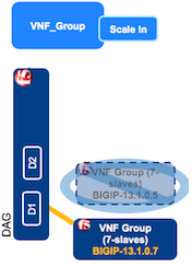
To scale in the old VNF layer, on the Deployments blade, click the old VNF group (running the old version of BIG-IP), at the top of the window click Execute workflow, select Scale In, enter the deployment_id for the old layer using the following format, and then click Scale In.
["gilanTestUG_vnf_group_f00jl8_vnf_layer_90ew6m_layer_id_q5dm8i"]
Tip
To find the layer ID of the old layer you are scaling in, click the Deployments blade, click the VNF_group being upgraded, scroll down to the Nodes pane, click the layer_id row, and the old layer will appear first in the list. Using the first layer ID in the list, on the Deployments blade search for the layer ID. Click that layer and at the top of the window, copy that ID.
This workflow destroys the old layer running the old version of BIG-IP. Now you have one upgraded layer, running the new version of BIG-IP. To verify the status of this workflow, click the VNF_layer deployment, and scroll down to the Deployment Executions pane and in the Scale In workflow row, the status column should display, Complete.
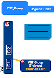
In VNF Manager, click the Deployments blade, click the VNF_group deployment you are upgrading, at the top of the window click Execute workflow, and then click Upgrade Finish.
On the Execute workflow upgrade_finish popup window, leave all other default values, and then click Execute.
This workflow clears the upgrade definition form you completed in Step 1, the Upgrade Start workflow. To verify the status of this workflow, click the VNF_group deployment, and scroll down to the Deployment Executions pane and in the Upgrade Finish workflow row, the status column should display, Complete.
Post auto-heal process
If deploying the Gi LAN or Gi-Firewall blueprint, the Heal workflow will run automatically on a VNF layer, DAG layer, or secondary deployment, when nodes become non-responsive or lose connectivity with the VNF primary node.
When a heal workflow runs automatically, the heal started indicator will appear on the Deployments blade, in the VNF_layer/slave_ID deployment type row:
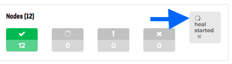
When the heal workflow runs automatically, a status appears on the pane:
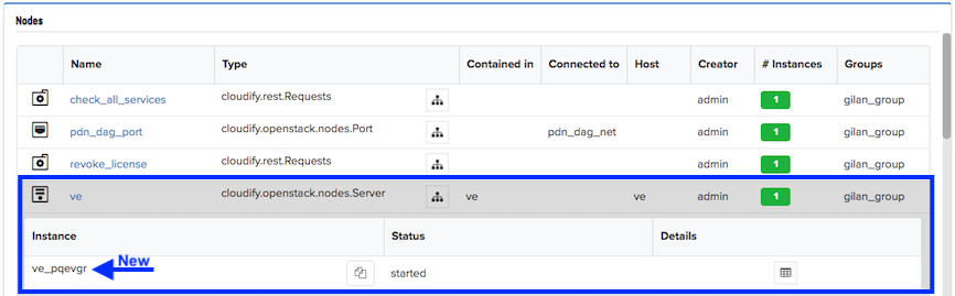
On the Deployments blade, find the secondary or the layer deployment that was healed, click the healed deployment to open it, and then scroll down to the Nodes pane.
In the Nodes pane, click the ve row, and if the heal ran successfully, two secondary/layer instances are listed; the old and the new instance.
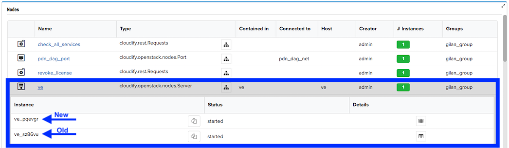
To purge the old instance, scroll to the top of the Deployment page, click Execute workflow, and then select Purge from the list.
On the popup menu, leave all default values, and click Execute. This workflow will bleed (like Admin State Disable) traffic off the old instance, removing it from the layer, leaving you with only the new instance.
Manually trigger Heal or Scale workflow from Nagios
F5 VNF Manager uses the Nagios component to monitor the various other components of the F5 NFV Solutions. Nagios determines if a component has failed, or if the current resources have breached their configured thresholds, and requires scaling out of more resources. Nagios exercises the Heal and or Scale workflows whenever its monitors are triggered, by sending REST calls to the F5 VNF Manager API that manages the solution. The F5 VNF Manager responds by running the required workflows and either heals or scales the appropriate components.
Use this procedure in the event that the F5 VNF Manager fails, and is restored using a clone or snapshot. These steps will clear any alarms or error conditions in the Nagios component of the F5 NFV solutions you have deployed, after you have fully recovered and restored the F5 VNF Manager. This process will re-trigger any Heal or Scale workflow on the VNF Manager that may have been triggered by Nagios, while the VNF Manager was offline.
Important
You MUST successfully restore the F5 VNF Manager from the latest snapshot BEFORE executing this procedure!
Connect to the Nagios Component
- Login to the F5 VNF Manager UI.
- Click the Deployments blade.
- In the Deployments list, click the Nagios component deployment that was created for the deployed F5 NFV solution blueprint.
- Scroll to the Deployment OutputsCapabilities pane, and then for the
http_endpointkey, copy the URL value. - Paste this URL into a browser window.
- When prompted for the Nagios login credentials, use the values defined in the following secrets:
- nagiosrest_user
- nagiosrest_pass
Determine if there are any failures
- After logging into the Nagios component, in the left-hand menu under the Current Status section, click the Hosts link. This page displays alerts or alarms you must address at this time.
- If all alerts/alarms appear Green, then you can log out of the Nagios component. If you need to re-trigger a workflow, do the following procedure.
Manually re-trigger the REST Call
- In the Hosts column, click the Host name.
- In the Host Commands menu, select the Send custom host notification link.
- On the right-side of the custom host notification form, enter a comment in the text box to record your reason for sending this event REST call.
- Click Commit to send the event REST Call and initiate the F5 VNF Manager workflow.
- Return to the F5 VNF Manager UI and monitor the logs to make sure the proper workflow starts and finishes, successfully.
Promote the secondary BIG-IQ during an HA-pair failover
If you deploy the BIG-IQ blueprint in an HA pair and your primary BIG-IQ falters, then you can promote the secondary BIG-IQ to manage the BIG-IP devices. Do the following to promote and fail over the management of resources and service layers:
On the Deployments blade, click the BIG-IQ deployment, at the top of the window click Execute Workflow, and then select Promote.
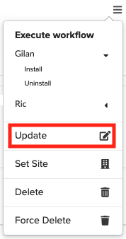
Once the promote workflow completes, click the BIG-IQ deployment, click Execute workflow, and then select Update from the list.
This workflow updates the mgmt IP address assigned to the BIG-IQ deployments. If the primary BIG-IQ fails, then both the primary and secondary deployments become standalone deployments, destroying the HA-pair. The secondary BIG-IQ takes the mgmt IP address of the failed primary BIG-IQ.
Update CGNAT address pool with more IP space
When you enabled CGNAT, you defined an address pool with ranges of IP addresses your system will use during orchestration. When you approach the exhaustion threshold of those defined address ranges, you can update the address pool with additional IP space using the Update cgnat IP workflow. Run this workflow for both CGNAT-Offering solutions and Gi-LAN/F solutions enabled with CGNAT.
Tip
To set up an alert to notify you when your system approaches the exhaustion threshold value (for example, 80% of addresses used), then use the REST API to poll the VNFM input value for this threshold value.
- On the Deployments blade, click the primary Gi-LAN, Firewall, or CGNT-Offering deployment, scroll to the top of the Deployment page, click Execute workflow, and then select Update cgnat IP from the list.
- On the popup menu, enter the CGNAT IP range using JSON format; for example, ‘192.168.1.100-192.168.1.150’ and ‘192.168.1.155-192.168.1.160’.
- Click Execute.
Attach additional BIG-IP VE syslog configuration file to a deployment
You can run this workflow for attaching an additional BIG-IP VE syslog configuration file to any of the blueprint solutions EXCEPT the VNF Base solution.
Caution: ONLY use this workflow with assistance from F5 Technical Support.
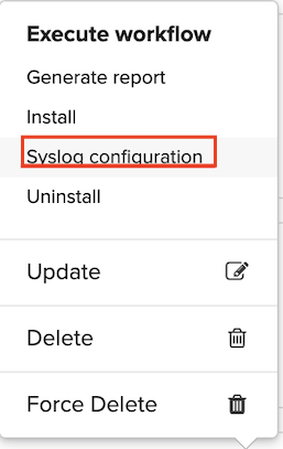
On the Deployments blade, click any primary blueprint (EXCEPT VNF Base), scroll to the top of the Deployment page, click Execute workflow, and then select Syslog configuration from the list.
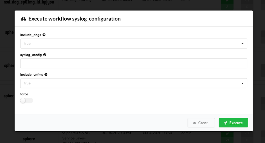
On the popup menu, complete the following parameters, and then click Execute:
- In the include_dags textbox, define whether to include syslog configuration information for your DAG layers. Valid entries include
trueorfalse. - In the syslog_config textbox, enter a valid BIG-IP VE syslog configuration; for example,
destination remote_server {tcp("10.10.10.13" port (514));}; filter f_alllogs {level (debug...emerg);}; log {source(local);filter(f_alllogs); destination(remote_server);};. - In the include_vnfms textbox, define whether to include syslog configuration information for your VNF Manager. Valid entries include,
trueorfalse.
- In the include_dags textbox, define whether to include syslog configuration information for your DAG layers. Valid entries include
Click Execute.
Add tmsh/bash commands to existing deployments
Execute the Update Declaration workflow, if you need to add configuration commands to existing blueprint deployments
beyond BIG-IP AS3 or REST. You can add tmsh/bash commands to any NSD deployment type. For a complete list of acceptable values, consult
the additional_commands input definition in the Inputs reference guide.
On the Deployments blade, click any NSD deployment type, scroll to the top of the Deployment page, click Execute workflow, and then select Update Declaration from the list.
In the Parameters dialog box, click Load Values, browse for a
.YAMLfile with your execution parameters to automatically complete the form, or manually define the following:Tip
Values are casted to types; for example, [1, 2] is casted to an array and 524 is casted to a number. Surround values with ” quotes to explicitly declare it as a string; for example,
"{"a":"b"}"is sent as string, NOT an object, and “true” is sent as string, NOT a boolean value. Use “” for an empty string.In the payload text box, enter the tmsh/bash commands that you want to execute on the blueprint solution using JSON or YAML format; for example:
["self_ip_control_net=$(tmsh list net self control_net_self address | grep address | awk -F' ' '{print $2}'|awk -F'/' '{print $1}') && echo Self ip of control_net interface is $self_ip_control_net"]In the type text box, enter CLI.
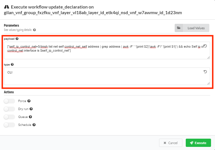
Click Execute.
These commands will execute AFTER the BIG-IP AS3 declaration, during deployment installation on an NSD node. Find the command results in the deployment logs, labeled with update_declaration workflow type.
Tip
You can update your BIG-IP AS3 declaration using this same procedure, substituting your updated BIG-IP AS3 configuration in the payload text box and entering AS3 in the type text box.
Enable CGNAT after solution deployment
When you have already launched a Gi-LAN or Firewall solution blueprint and you want to enable CGNAT, you can do so by
defining a new vnf_as3_nsd_payload BIG-IP AS3 declaration, and new inputs in your inputs file, and then executing the Enable CGNAT workflow.
- Open your local inputs YAML file that you deployed for the existing Gi-LAN or Firewall blueprint, edit the BIG-IP AS3 declaration with a vnf_as3_nsd_payload section, (specifically the policyNAT declaration) and add the CGNAT-related inputs. For more information, consult the Schema Reference.
- In VNF Manager, click the primary blueprint deployment for Gi-LAN or Firewall solution, scroll to the top, and then click Execute Workflow.
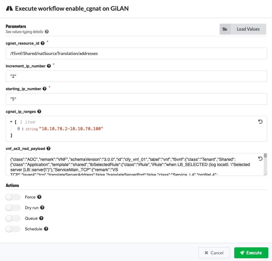
- Select Enable CGNAT from the list, provide the following parameter definitions or
click Upload Values to browse for the updated YAML file (edited in step 1) with the following inputs defined, and then click Execute:
- cgnat_resource_id - Enter the reference/pointer to
/f5vnf/Shared/natSourceTranslation natSourceTranslation: addresses:in thevnf_as3_nsd_payloadadded using the followingvnf_as3_nsd_payloadinput and executed with the Enable CGNAT workflow. This is your NAT source translation pool that you want VNFM to manage (for example, “/Sample_22/A1/”). - increment_ip_number - Enter the value by which your IP addresses are added to your deployment, when you run the Increment IP workflow. Default value is 2.
- starting_ip_number - Enter the number of IP addresses initially assigned to each VNF VE. Default value is 5.
- cgnat_ip_ranges - Enter the IP address range in JSON format for each address list (for example, ‘192.168.1.100-192.168.1.150’ and ‘192.168.1.155-192.168.1.160’)
- vnf_as3_nsd_payload - Enter the vnf_as3_nsd_payload for a Gi-LAN or Gi-Firewall deployment in JSON format (ONLY).
- cgnat_resource_id - Enter the reference/pointer to
Scale out layers for CGNAT Offering blueprint
A Scale out workflow runs when the vnf_layer_throughput_threshold input value is exceeded. Nagios automatically triggers a
workflow responsible for executing the Scale Out operation. The scale out operation determines how many sub-layers are
added to your available resources, and is what the RIC billing workflow uses to determine your throughput consumption.
You can obtain and control the values that the Scale Out workflow uses and add a new sub-layer on the Nagios deployment, using the VNF Manager console. Doing so enables you to manually control the number of machines you want to add/remove.
- Start your VNF Manager console, in the left menu, click Deployments, and then in the nagios_server
row click .
- Select the Scale Out option.
- Complete the popup form, defining the number of instances to add to the layer. All instances are installed simultaneously,
and instances are not waiting for each other. The number of CGNAT instances on the layer appears in the
cgnat_instance_countoutput value (found in the pane).
Deploy BIG-IP VE HA pair in Cloudify 5.05
If you do not use the F5 VNF Manager solution, but purchased the F5 Gilan Plugin 2.1.0, you can use it to instantiate a pair of BIG-IP VEs for high availability purposes in a Cloudify 5.05 Web app. Use this F5 plugin with your own solution blueprints and Cloudify 5.05 workflows to orchestrate and manage your NFV resources.
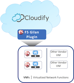
The F5 Gilan Plugin uses F5 Cloud-libs, F5 BIG-IP AS3, and your custom scripts for the BIG-IP VEs to perform onboarding tasks, such as:
- Licensing VMs
- Assigning and routing IP addresses
- Configuring service settings (iRules, virtual servers, and pools)
- Configuring device settings (cluster, VLAN, Self IP, DNS, and NTP)
- Configuring base operating system settings
System requirements
Using the F5 Gilan Plugin for Cloudify 5.05 requires the following system setup components:
- OpenStack Newton version 10 or Queens version 13 VIM
- A configured Cloudify version 5.05 Web app
- One of the following supported BIG-IP VE images:
Use the example F5-bigip-demo-cloud-libs blueprint
For an OpenStack example blueprint, point your browser to the F5 Networks NFV-solutions Github repository. Follow the instructions in the readme file for uploading the F5 Gilan Plugin to your Cloudify 5.05 Web app, and deploying the example F5-bigip-demo-cloud-libs blueprint solution.
Configuration workflows
Caution
The Configuration workflow category is empty and does nothing.
Suspend workflows
Caution
The workflows you find in the Suspend category do nothing when run manually. These workflows run automatically, during blueprint orchestration. For manually run workflows, expand the Gilan and Ric categories. For working solutions, consult the Backup and Restore Guide.
Rest workflows
Caution
The workflows you find in the Rest category do nothing when run manually. The Hook workflow rest option runs automatically, during blueprint orchestration. For manually run workflows, expand the Gilan and Ric categories.
Terminal workflows
Caution
The workflows you find in the Terminal category do nothing when run manually. These workflows run automatically, during blueprint orchestration. For manually run workflows, expand the Gilan and Ric categories.
What’s Next?