VNFM setup guide
Download the VNF Manager image from the F5 Downloads site. Upon purchasing a VFNM solution, you receive an email with an associated product license key (ric_vnfm_serial).
In this guide you will also find specific setup descriptions for enabling:
- Integrated CGNAT or using the CGNAT-Offering blueprint (for VNFM 2.0 and later)
- DNS-standalone capabilities
- DNS Security VNF Service capabilities
Prerequisites
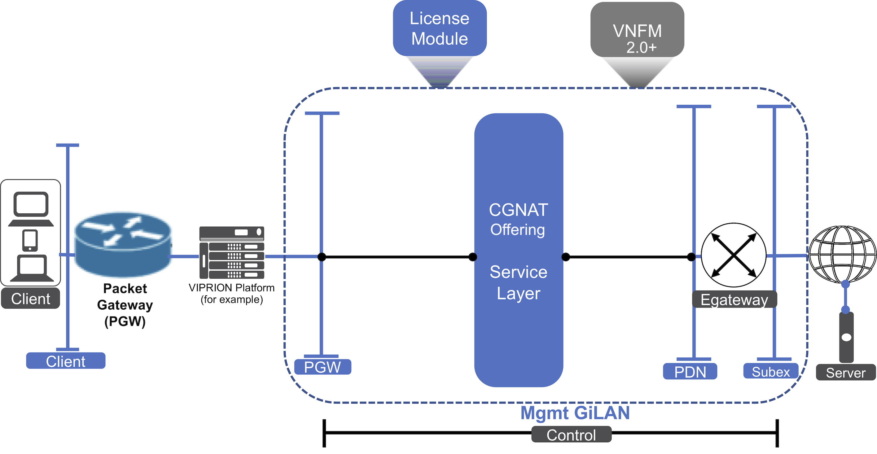
F5 VNF Manager requires the following system networks and components be configured and running in your virtualized infrastructure manager (VIM) or private cloud environment, as depicted in the following diagram.
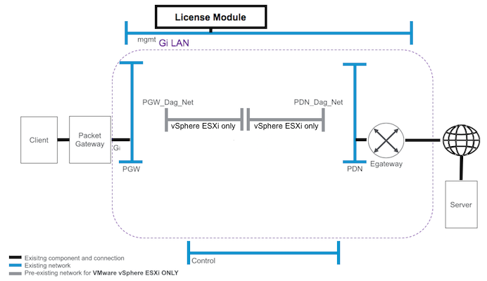
Pre-existing networks and components
As displayed in the previous diagram, VNFM requires that your environment have the following, preexisting components and networks configured PRIOR to installing a VNFM image:
- Management network (mgmt) and subnet accessible to the Internet, which the VNFM will use to manage deployment of your cloud resources, connecting BIG-IPs to the BIG-IQ and the VNF Manager.
- Packet gateway network (pgw) and subnet is the provider network on the subscriber side of the Gi-LAN, transporting application transactions.
- Provider network (pdn) and subnet is the provider network on the packet data network (Internet) side of the Gi-LAN, transporting subscriber packets to your internal, provider servers.
- Control network and subnet represents where the F5 NFV solutions connect to processes such as, your policy and control rules function engine, subscriber service-charging functions, signaling, and other similar processes.
- PGW_Dag_Net and subnet is the internal, provider network on the subscriber side. For VMware ONLY, VNFM requires that you create this network manually. For OpenStack users, VNFM creates this network automatically, during the launch process.
- PDN_Dag_Net and subnet is the internal, provider network on the packet data network (Internet) side. For VMware ONLY, VNFM requires that you create this network manually. For OpenStack users, VNFM creates this network automatically, during the launch process.
Other configuration setup requirements
Other network setups and components not depicted in the diagram include:
- Shared storage in OpenStack used for storing virtual machines or in vSphere shared storage/datastore cluster used for virtual machines and content library that requires write-access.
In addition to networks depicted in the previous diagram, you must also download and launch the following supported F5 products in your VIM. Download the file extension type (qcow2 or OVF) required by your VIM:
| Supported Platforms | Description |
|---|---|
| F5 VNF Manager image | Download the VNF Manager image qcow2 (OpenStack) or OVF (vSphere/vCloud) file from the F5 Downloads site. Upon purchasing F5 VNF Manager, you receive an email with a license key. |
| BIG-IQ 6.0.1 or 8.2.0.1_Virtual-Edition from F5 Downloads using F5-BIQ-VE-LIC-MGR-LIC license key | This activates the BIG-IQ License Manager utility module that manages licensing for BIG-IPs (utility pools) during orchestration. For OpenStack select the .qcow2 file and for ESXi
select the .OVA file. Due to a limitation of BIG-IQ Version 8.2.0.1,
deploying BIG-IQ blueprint solution without DHCP requires L2 connectivity between VNFM and BIG-IQ machines. BIG-IQ REQUIRES a policy-compliant password. See knowledge article K49507549 for complete details.
Before launching F5 VNF Manager, you must manually configure the BIG-IQ License Manager, or deploy the BIG-IQ blueprint to automate this process. |
Caution
For environments without DHCP, the first time VNFM boots up, certificates are generated that are used for communicating between internal VNFM services. The certificate-generating service waits eight minutes for VNFM to be assigned an IP address. Since there is no DHCP in the environment, you must manually assign an IP address for the VNFM within eight minutes; otherwise, you will get the following VNFM status error message, and then MUST reinstall VNFM:
An SSL-related error has occurred. This can happen if the specified REST certificate does not match the certificate on the manager. Underlying reason: HTTPSConnectionPool(host='127.0.0.1', port=443):
Max retries exceeded with url: /api/v3.1/status (Caused by SSLError(SSLError(1, '[SSL: CERTIFICATE_VERIFY_FAILED] certificate verify failed (_ssl.c:877)’),))
| Supported Platforms | Description |
|---|---|
| BIG-IP 15.1.5.1 or 16.1.2 Virtual Edition ALL_1SLOT from F5 Downloads site with F5-BIG-MSP-LOADV12-LIC license key | Use the Utility License, automatic method (if connected to the Internet) or the manual method (if not connected). |
| CentOS-7-x86_64-GenericCloud-1503 | Image used by VNFM blueprints to create the Nagios virtual machine that monitors BIG-IP VE’s. This image is used specifically for environments connected to the Internet. |
| Prebuilt Nagios image (for dark environments in OpenStack only) | The virtual machine image used by VNFM blueprints for monitoring BIG-IP VE’s. This image is required specifically for OpenStack environments that are NOT connected to the Internet (dark environments). You will download this prebuilt Nagios image using the link in the purchase confirmation email. |
Set up your VIM
- Complete the setup for one of the following, supported VIM configurations:
- OpenStack
- VMware vSphere ESXi
- Multi-VIM setup (for deploying to multiple data centers in either OpenStack and/or vSphere)
- To download the VNF Manager image locally, point your browser to the F5 Downloads site. The email receipt from F5 Networks contains the license key.
You have the following choices of image types:
- For OpenStack you will download a
.qcow2file - For VMware you will download a
.OVAfile
- For OpenStack you will download a
- Point your browser to the following component sites, and download the image file extension compatible with your VIM:
- BIG-IQ 6.0.1.0.0.813 or 8.2.0.1 Virtual Edition from F5 Downloads site, narrow your product search to BIG-IQ-Centralized Manager, select the Virtual Edition product container, select the file type appropriate for your VIM (OpenStack select qcow2 and VMware select OVA), and then download the product using the F5-BIQ-VE-LIC-MGR-LIC key.
- BIG-IP 15.1.5.1 or 16.1.2 Virtual Edition ALL_1SLOT from F5 Downloads, narrow your product search to BIG-IP, select the Virtual-Edition product container, select the appropriate file type for your VIM (OpenStack select qcow2 and VMware select OVA), and then download using the F5-BIG-MSP-LOADV12-LIC key (1SLOT image required for sufficient disk space).
- CentOS download site, and then download the CentOS-7-x86_64-GenericCloud-1503.qcow2 package for OpenStack or the OVF package for VMware. Use this image for environments connected to the Internet.
- Nagios download site, and then download the nagios image name package for OpenStack. Use this image for environments NOT connected to the Internet (dark environments).
- Upload all the previously downloaded images into your private, VIM project. For detailed instructions visit docs.openstack.org for v13, Red Hat product guide for OpenStack 16.2, or VMware Docs.
- You must license and configure the BIG-IQ License Manager utility pool or use the BIG-IQ blueprint to automate this step BEFORE deploying F5 VNFM blueprint solutions.
- Deploy your F5 VNF Manager solution.
Post-deployment system overview
When finished deploying your VNFM, you will have the following system:
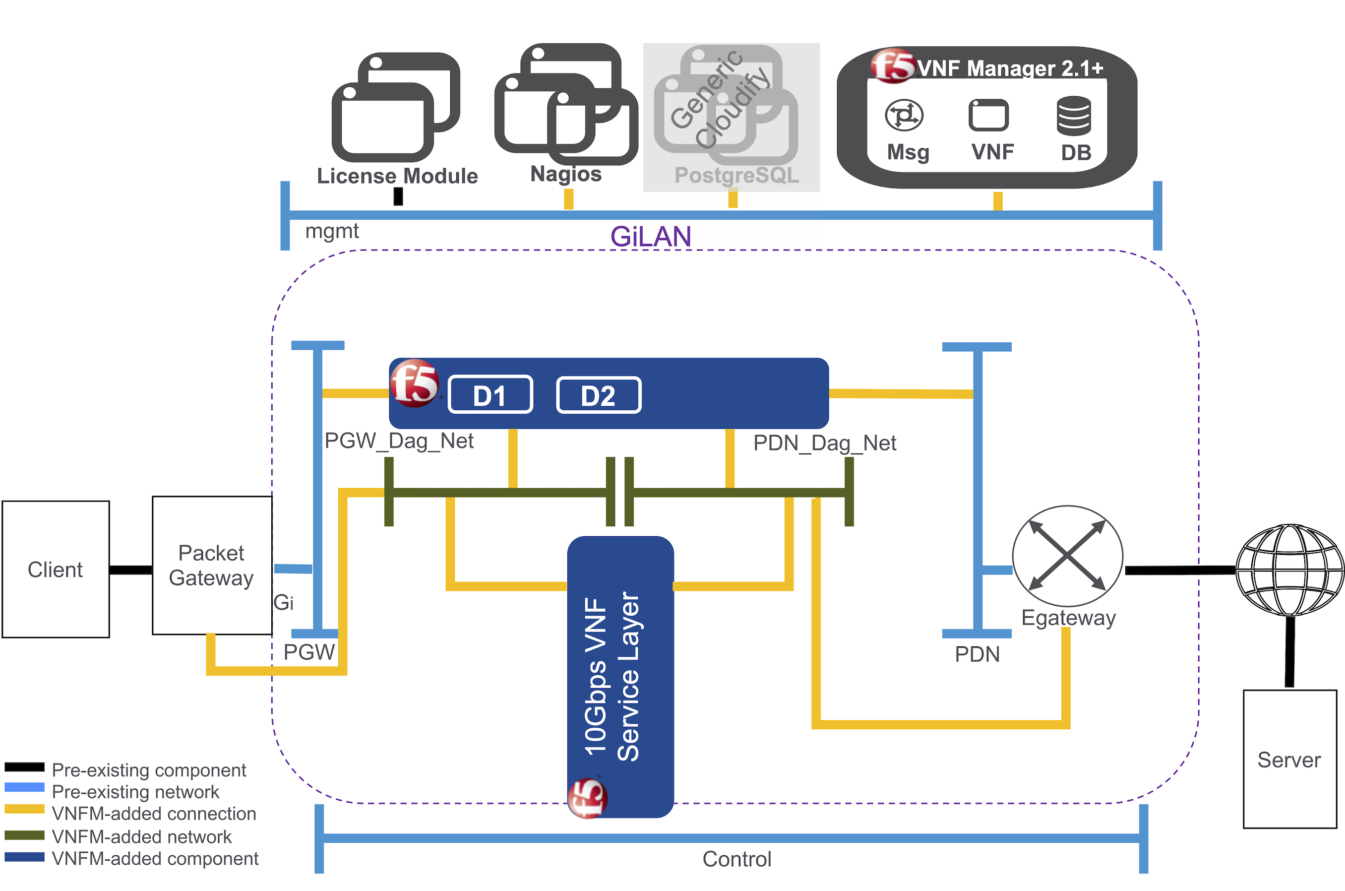
Once you upload BIG-IQ, BIG-IP, and the VNFM images into your cloud environment (for example, OpenStack or VMware), and deploy the VNFM blueprint, then your management network will also connect the BIG-IQ license manager, a Nagios module for monitoring VE scale-out, a PostgreSQL database (only generated when using a generic Cloudify manager), the BIG-IPs deployed by the blueprint, and your F5 VNF Manager.
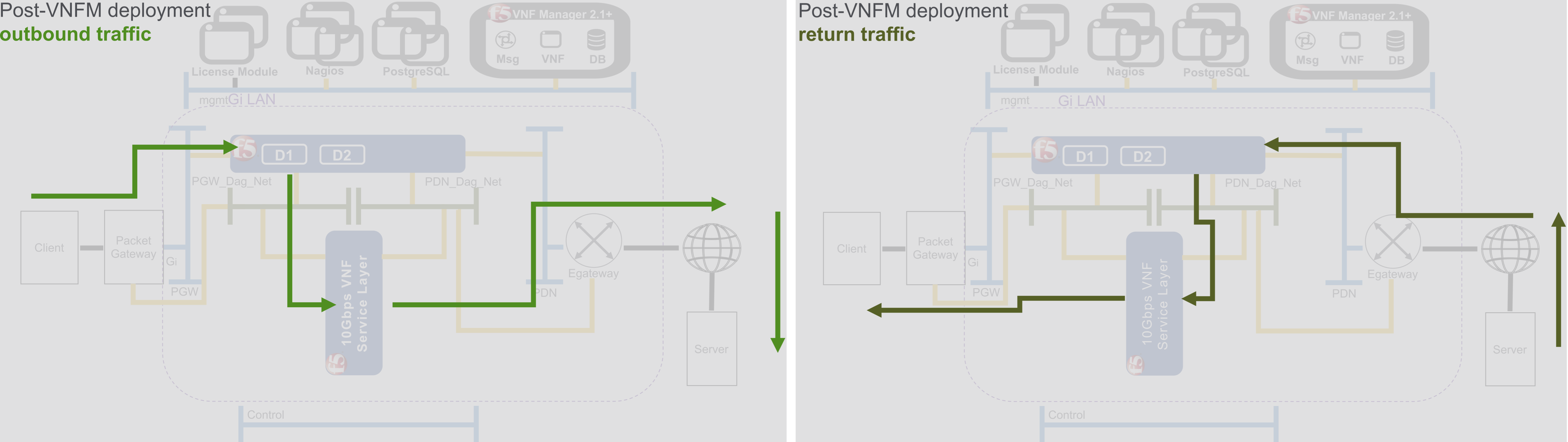
Client network outbound traffic flows from the packet gateway, into the disaggregation (DAG) tier where it is distributed to a service layer that is comprised of BIG-IP VE - virtual machine (VM) instances. The VEs in the service layer perform operations like TCP optimization. As traffic throughput increases, the service layers will auto-scale or add VMs until the layer reaches the maximum throughput that you purchased. Traffic exits the service layer directly towards the external gateway, and bypasses the DAG on the way to its destination.
Return traffic flows from the external gateway into the DAG tier, where it is returned back to the VE in the service layer that originally handled the outbound traffic. This ensures that typical asymmetric traffic returned to the solution remains symmetric inside the solution. Any additional processing of network traffic is done by the VE in the service layer, and then traffic is returned directly back to the packet gateway and back to the client, again bypassing the DAG tier.
Set up CGNAT
You have two options for implementing CGNAT functionality for VNF service layer(s) that includes a set of BIG-IP AS3 declaration modifications and configured inputs:
- Integrated CGNAT – for VNFM 1.3 and later using BIG-IP AS3 declaration modifications deployed by either a Gi LAN or Gi Firewall solution and a large-scale NAT address pool.
- CGNAT-Offering blueprint – for VNFM 2.0 and later implementing a single VNF service layer without a DAG when your VNFs are homed on different networks. Deploying the CGNAT-offering consists of one group and one layer with one CGNAT VE instance; however, you can define an input, enabling you to choose the number of CGNAT VE instances you want to create during deployment.
Set up an integrated CGNAT
This CGNAT functionality uses a set of BIG-IP AS3 declaration modifications and configured inputs, deployed by either a Gi LAN or Gi Firewall solution in an OpenStack or Vsphere environment for F5 VNF Manager version 1.3.0 and later.
To implement CGNAT capabilities, you require the following:
| Component | Description |
|---|---|
| Deployed F5 VNF Manager 1.3.X and later prerequisites | A deployed VNFM version 1.3.X and later with all the required F5 products: An F5-VNF-Service-Layer-Gilan or Firewall blueprint:
For a complete list of component and network requirements, consult the prerequisites topic. |
| VNFM plugins | The f5-gilan and f5-ric plugins. |
| Large-scale NAT address pool | Pool of carrier-grade end sites configured with private network addresses, translated to public IPv4 or IPv6 addresses, using an address translator. The CGNAT-enabled Gi LAN/Firewall deployment BIG-IP AS3 configuration will use the address pool during scaling. You must configure your address pool with discrete IP sets, which can originate from different subnets or VLANs. VNFM will, at minimum, assign five IPs to each VNF secondary instance, so be sure to provide enough IP addresses in your address list. |
Tips for enabling CGNAT
Consult the following video to help configure CGNAT. Be aware that the version of VNFM used in this video may not match the version you are currently using.
When finished deploying a F5 VNFM Gi LAN/Firewall solution blueprint with a CGNAT BIG-IP AS3 declaration, you will have the following system:
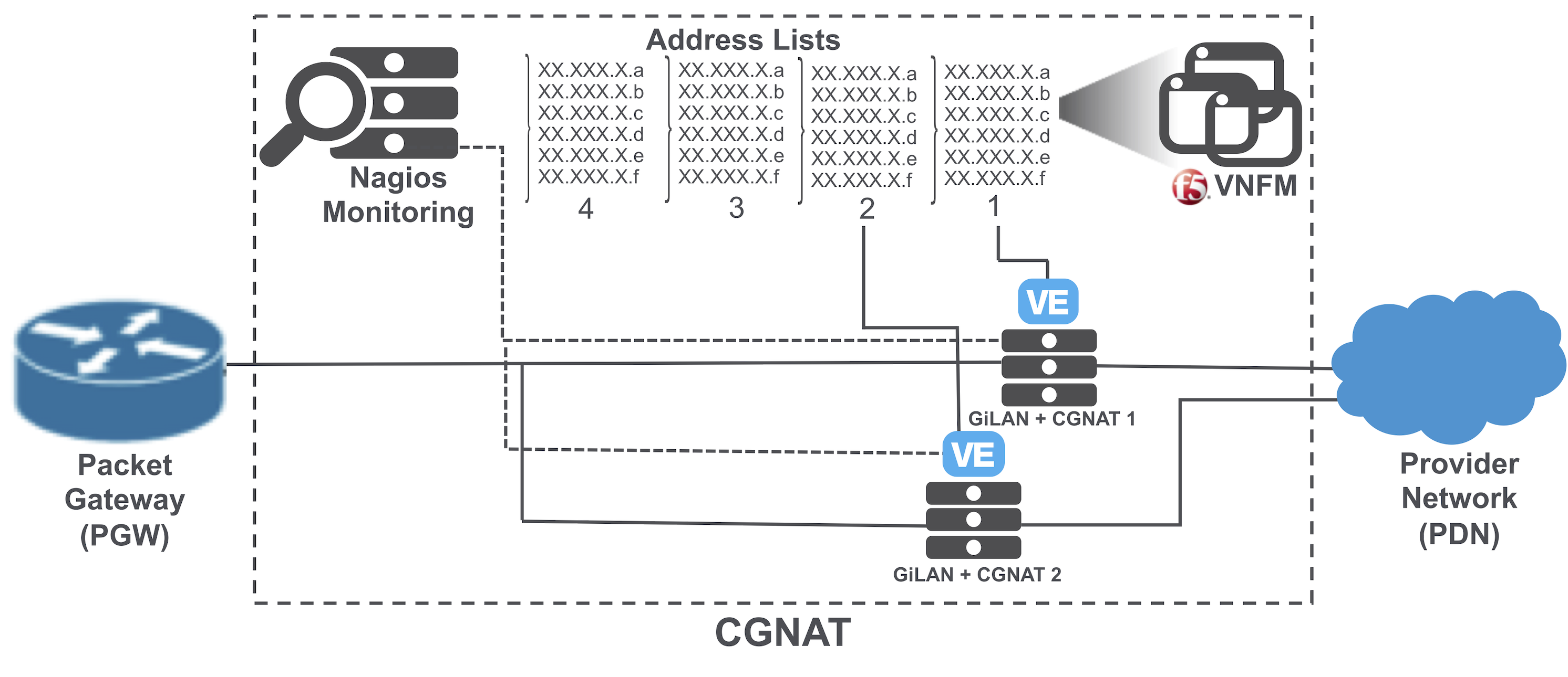
The previous diagram illustrates a limited four-list, Gi LAN+CGNAT deployed by a modified BIG-IP AS3 declaration for configuring CGNAT with scaling forced by Nagios, and based on CPU usage. F5 VNFM manages the address pool you defined in the inputs as lists of IP addresses. Each instance of the CGNAT VE will take the configuration from the VNFM-managed pool of addresses, use one address list, and then update the group outputs with the used address list.
Set up for CGNAT-Offering blueprint solution
The CGNAT-Offering blueprint solution for VNFM 2.0 and later does NOT contain a disaggregation layer. Therefore, you must provide the management layer that directs external traffic and maintains persistence to the deployed CGNAT-Offering blueprint solution.
For example, you can do this using pre-existing F5 Hardware to load balance traffic and to maintain persistence for connections to the CGNAT-Offering solution. Consider this solution a hybrid of hardware and virtualization that uses hardware to provide the disaggregation or DAG layer and provisioning for the Advanced Firewall Management module.
This environment does not utilize the PGW_DAG_NET or PDN_DAG_NET networks like the CGNAT for GiLAN/Firewall solutions. Instead, the CGNAT VNF’s are directly connected to the PGW, and PDN networks. The CGNAT-Offering solution lacks primaries or subsidiaries, but instead deploys just CGNAT VNF’s in a single scale group.
To deploy CGNAT-Offering blueprint, you require the following:
| Component | Description |
|---|---|
| Deployed F5 VNF Manager 2.0.X and later prerequisites | A deployed VNFM version 2.0.X and later with all the required F5 products:
For a complete list of component and network requirements, consult the prerequisites topic. |
| VNFM plugins | The f5-gilan and f5-ric plugins. |
| Large-scale NAT address pool | Pool of carrier-grade end sites configured with private network addresses, translated to public IPv4 or IPv6 addresses, using an address translator. The CGNAT-Offering deployment BIG-IP AS3 configuration will use the address pool during scaling. You must configure your address pool with discrete IP sets, which can originate from different subnets or VLANs. VNFM will, at minimum, assign eight IPs to each CGNAT VNF, so be sure to provide enough IP addresses in your address list. |
The setup for implementing the CGNAT-Offering blueprint requires the following:
- Properly configured CGNAT-related inputs.
- Configured VNFs that advertise their 0.0.0.0/0 route back to the PGW, once active. This solution configures and utilizes BGP ECMP to learn the routes back to the clients from the PGW.
- This solution configures BGP ECMP to advertise to the Egateway more specific routes back to the NAT addresses; thereby, persisting connections to individual NAT addresses.
Once finished, you will have the following solution:
CGNAT-Offering deployment outbound traffic flow includes:
- The client sending traffic destined for a server
- Client routing packets to the PGW via the client’s default route
- PGW forwarding packet to one of the NAT devices
- BGP learning the next hop from the NAT device neighbors and since there are multiple neighbors, there are multiple next hops of equal cost/equal-cost multi-path (ECMP) routing
- ECMP using a hash to pick a next hop
- NAT device performing the translation and forwarding a new packet toward the server using its default gateway
- Defining inputs that determine the default gateway used for the layer deployment
CGNAT Offering deployment auto-processes
Automatic scale out of CGNAT-offering VEs occurs when:
- The TMM CPU usage of all the CGNAT layer instances exceeds the defined threshold value, a new instance is added to the CGNAT layer.
- The percentage of average aggregate CGNAT layer throughput exceeds the defined threshold, a new instance is added to the CGNAT layer.
You can consult the log files, to find out why your CGNAT scaled out automatically.
Automatic increment of IP addresses occurs when the virtual server processes a large number of new connections, and the CGNAT port pool becomes exhausted. When VNFM detects this condition, the increment IPs (proxy) workflow runs automatically.
For more information, consult the CGNAT Offering FAQ.
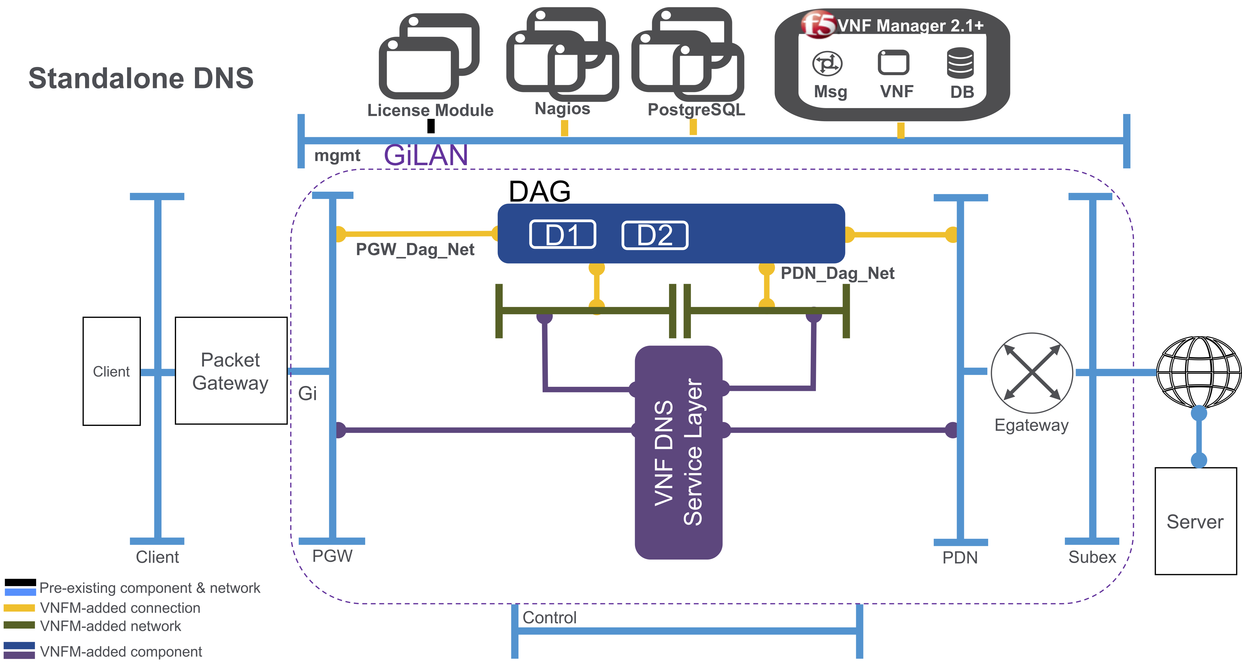
Set up for a standalone DNS blueprint solution
The standalone F5 DNS VNF service solution queries and translates names for client requests to/from the Internet, translating top-level Internet domains, such as .com, /net, .gov, .edu, and .org, as well as the following F5 Global Traffic Manager-based processes:
DNS Resolver used to cache DNS responses
DNS Cache (also known as, DNS Resolver Cache), a temporary, system-maintained database containing records of all recent visits and attempted visits to Websites and other Internet domains
Authoritative DNS system that takes a Web address, like F5.com, and provides an answer about the resources in that zone
Scaling and usage-billing based on queries packages cleaned per second (QPS) - once you reach the internally define threshold, VNFM will auto-scale an additional layer to meet your system demands.
Billing package options for both Perpetual and Subscription include:
- DNS (500K QPS)
- DNS (2M QPS)
Note
Currently, this DNS NFV solution does NOT support queries that require PEM/Subscriber awareness, or a third-party/subscription (for example, Webroot).
You require the following components when deploying a DNS VNF Service blueprint solution:
| Component | Description |
|---|---|
| Deployed F5 VNF Manager 1.3.1 prerequisites | A deployed VNFM version 1.3.1 and later with all the required F5 products:
For a complete list of component and network requirements, consult the prerequisites topic. |
| VNFM plugins | The f5-gilan and f5-ric plugins. |
The DNS solution will deploy into the same space as the Gi LAN solution; such as, between the packet gateway and the Internet. When finished deploying a standalone F5 VNFM DNS solution blueprint, you will have the following system:
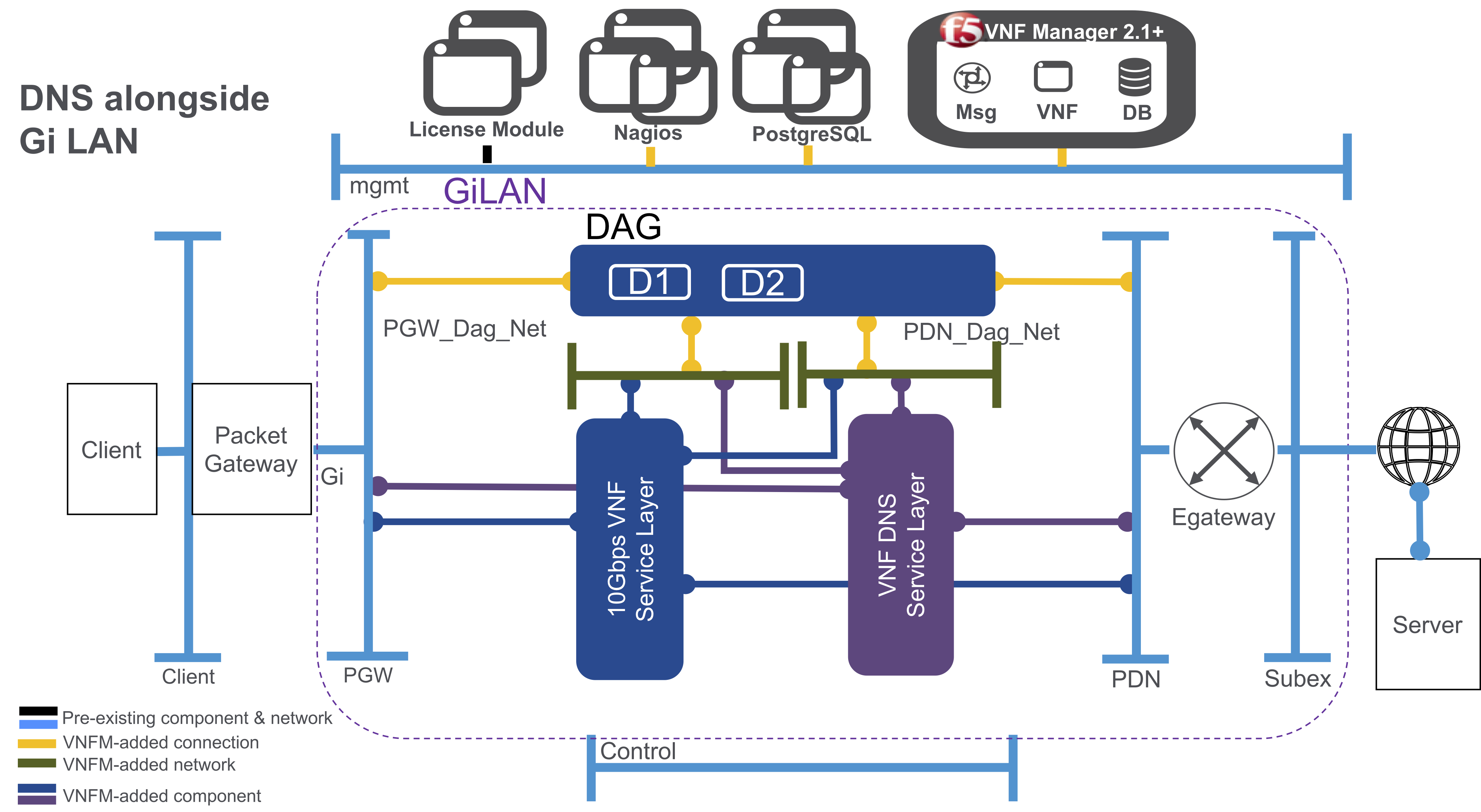
Enable DNS alongside existing Gi LAN deployment
You can also deploy the standalone DNS solution blueprint from VNFM alongside an existing Gi LAN/F deployment, so both service layers will deploy between the packet gateway and the Internet:
Billing package options for both Perpetual and Subscription include:
- DNS (500K QPS)
- DNS (2M QPS)
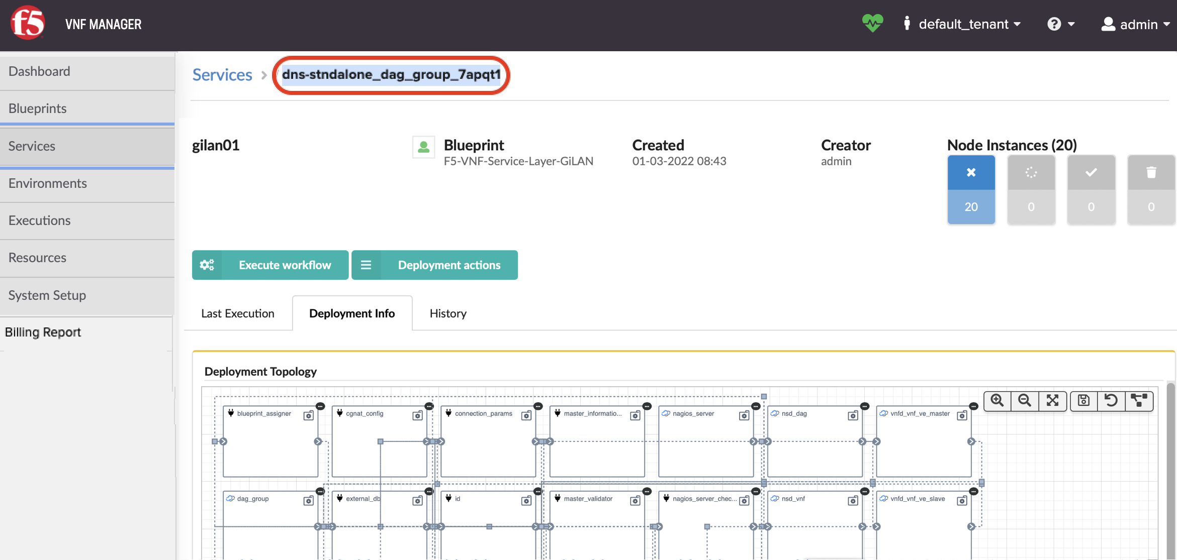
To add a DNS solution blueprint to an existing Gi LAN deployment, define the <input_name> with the existing dag_group ID of that existing Gi LAN deployment.
To find the Gi LAN/F dag_group ID
In VNF Manager click the Services blade, and then click Details for the dag_group service.
In the top-left corner of the Service page, copy and paste the deployment ID into the <input_name> input in the inputs file that you will use for deploying the DNS solution blueprint.
Deploy your DNS solution blueprint.
To help define inputs and an BIG-IP AS3 Declaration for your DNS solution, use the sample inputs file in the VNFM GitHub repository.
Set up for DNS Security VNF Service blueprint solution
This is a single-purpose, DNS Security VNF Service blueprint, specifically designed to clean DNS queries. This security solution also includes a Standalone DNS security service layer based on the F5 Advanced Firewall Manager.
Using the following components, you can secure your client DNS queries:
| Component | Description |
|---|---|
| Deployed F5 VNF Manager 1.4 or later prerequisites | A deployed VNFM version 1.4 or later with all the required F5 products:
For a complete list of component and network requirements, consult the prerequisites topic. |
| VNFM plugins | The f5-gilan and f5-ric plugins. |
When finished deploying a F5 VNFM Secure-DNS solution blueprint with a DNS-enabled BIG-IP AS3 declaration, you will have the following system:
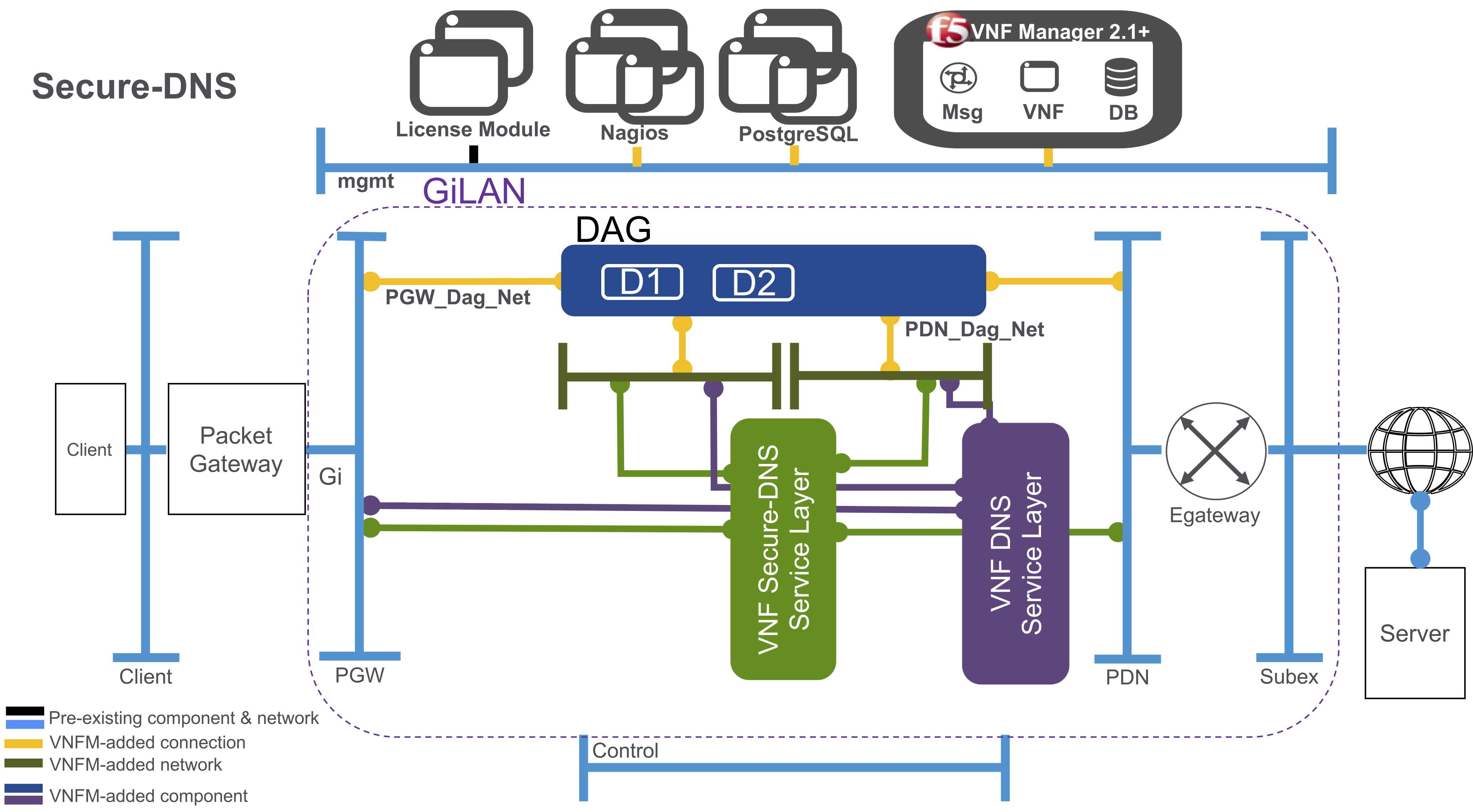
Your DNS Security VNF Service deployment will contain the following:
Virtual server - accepting port 53 TCP and UDP traffic only
Address pool - containing the VNF DNS Firewall IP addresses only
An iRule and data group - supporting the return traffic of the DNS
Scaling and usage-billing based on queries packages cleaned per second (QPS) - once you reach the internally define threshold, VNFM will auto-scale an additional layer to meet your system demands.
Billing package options for both Perpetual and Subscription include:
- DNSSEC (250K QPS)
- DNSSEC (500K QPS)
- DNSSEC (2M QPS)
You can also deploy the DNS Security VNF Service solution blueprint from VNFM alongside an existing Gi LAN/F deployment, so both service layers will deploy between the packet gateway and the Internet:
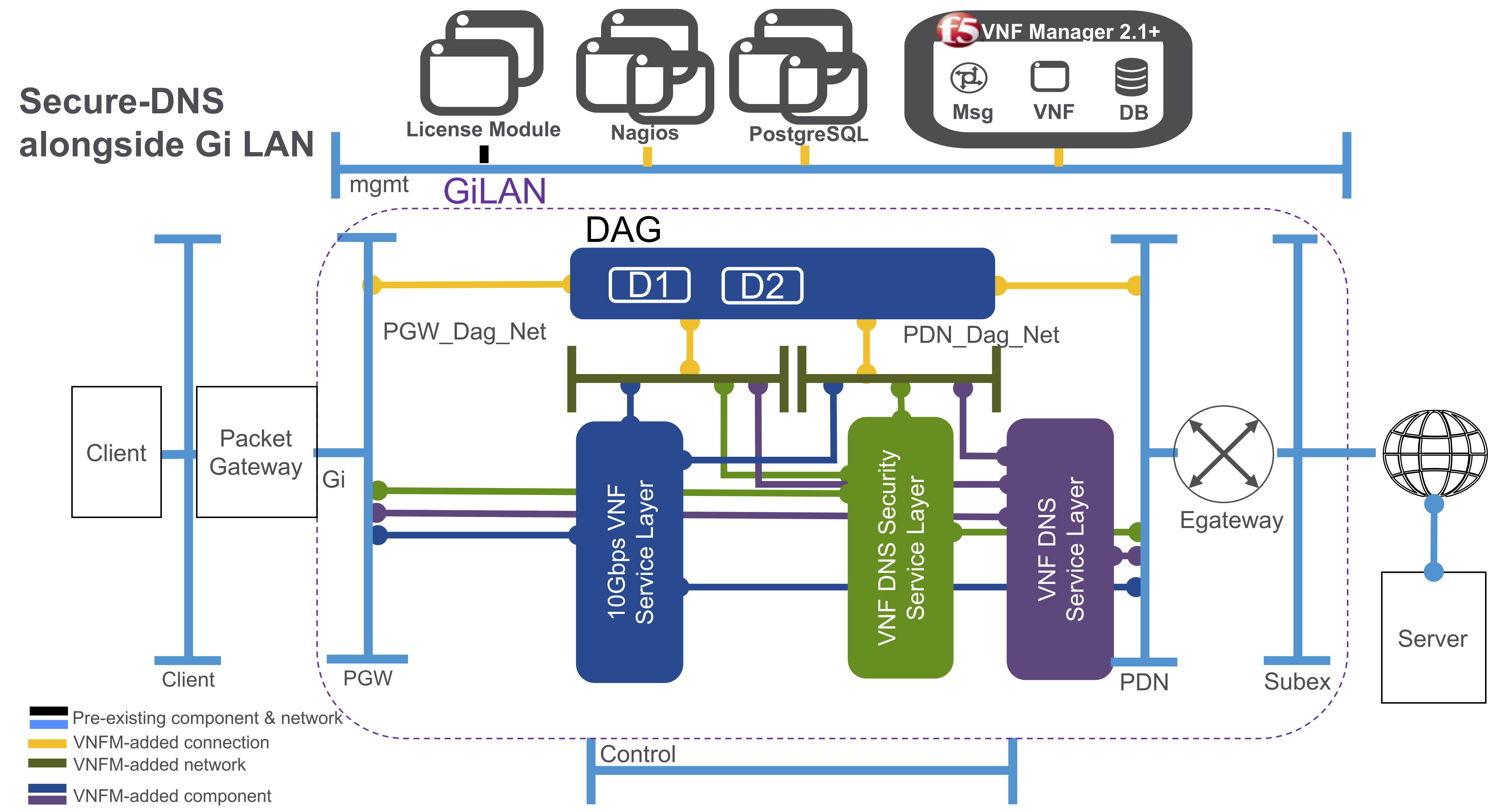
To help define inputs and an BIG-IP AS3 Declaration for your Secure DNS solution, use the sample inputs file in the VNFM GitHub repository.
Set up SR-IOV for VNFM
Single root I/O virtualization (SR-IOV) interface is an extension to the PCI Express (PCIe) specification, and enables network traffic to bypass the software switch layer of the virtualization stack. Because the virtual function (VF) is assigned to a child partition, the network traffic flows directly between the VF and child partition. Use SR-IOV to achieve virtualization and do the following:
- Enable efficient sharing of PCIe devices
- Optimize performance and capacity
- Create VFs and associate them with a single physical function (PF)
- Extend the capacity of a device and minimize hardware costs
To configure SR-IOV for VNF Manager, you will need a configured licensing module, a deployed VNFM image, and a Nagios image for monitoring purposes. Once you configure SR-IOV for VNF Manager, you will have the following setup:
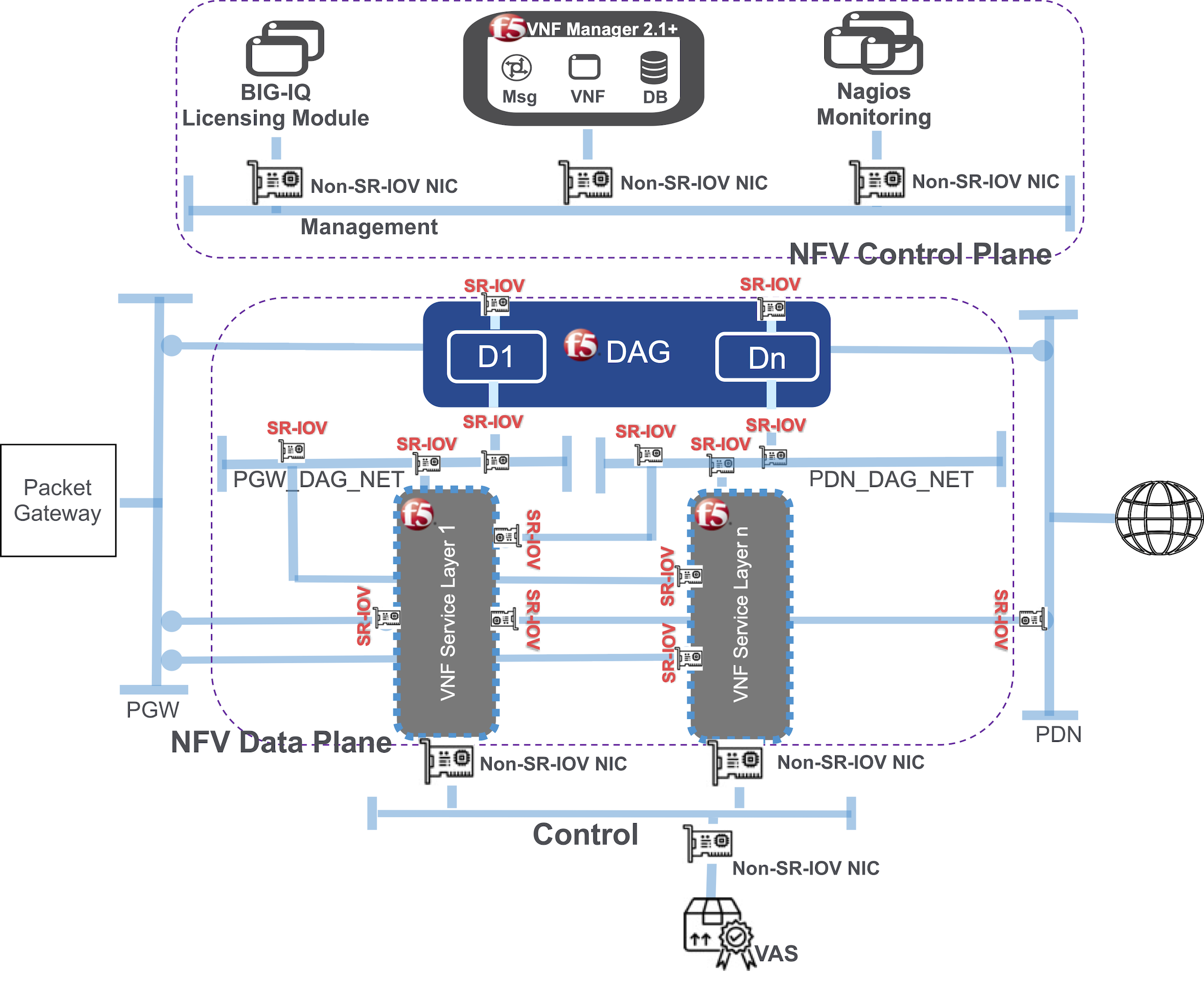
Use non-SR-IOV NICs connecting the control plane to the management network, and SR-IOV NICs connecting the service layers to the DAG in the data plane.
Traffic that requires dedicated SR-IOV Interfaces include:
- For DAG (two interfaces):
- PGW - to receive traffic from PGW (outbound flow)
- PDN - to receive traffic from PDN (return flow)
- VNF (two Interfaces):
- PGW_DAG_NET - to forward traffic directly to PGW after was received from DAG (return flow)
- PDN_DAG_NET - to forward traffic directly to PDN after was received from DAG (outbound flow)
The high-speed interfaces with SR-IOV NICs control the forward traffic between DAG and VNF in both return and outbound flows. Therefore, you require four interfaces for each DAG and 3-4 Interfaces for each VNF.
Base SR-IOV install example
For a base install of one service layer, expect to have 17 SR-IOV ports total - 8 ports for 2 DAGs and 9 ports for 3 VNFs (1 primary and 2 secondaries if there is no need to send traffic out to a VAS prior to forwarding to the Internet). The servers in the virtualization infrastructure require physical SR-IOV NICs. For example, requiring 17 to 20 dedicated 10G or 40G NICs for data plane traffic in a 10G or 50G VNF service layer. For even more throughput, requiring more servers and NIC interfaces.
However, the Intel X710 or XV710 (10Gbps and 40Gbps cards) support up to 64 SR-IOV instances per physical interface (configure only 8 or 16 per interface). These NICs come with 1, 2, or 4 interfaces. So, you can configure the servers with two of these NICs; one each on separate PCIe buses, so that each has direct access to a separate NUMA node (CPU Socket). This configuration does NOT suffer degradation, because it does NOT cross the NUMA boundary.
Based on the previous set up, only two dual port NICs are installed in each server:
- One NIC per Socket.
- In the hypervisor (VMware or OpenStack), each port (four ports, if configured like the previous example) is configured to break out into 8 or 16 individual SR-IOV ports.
- 16 x 4 = 64 SR-IOV ports per server, totaling 32 SR-IOV ports per NUMA/Socket.
For complete SR-IOV setup information, see Enable SR-IOV on ESXi for BIG-IP VE in vSphere ESXi.
Secure VNF Manager
Security, in the context of a VNF Manager, means securing communication with the VNF Manager and controlling who has permissions to use it to execute operations. Secured communication is achieved using SSL, which allows clients to validate the authenticity of the VNF Manager, and to ensure that the data sent to and from it is encrypted. Controlling access to VNF Manager, and permissions to perform actions, is implemented via Flask-Security, to support user authentication and authorization.
VNF Manager is secured by default. It cannot be bootstrapped in a non-secured way. For details about VNFM’s SSL and Access Control implementation and configuration, consult the following description:
VNFM security for client access focuses on the REST service, which this is the first and only access point of clients to VNF Manager. All requests to VNF Manager are authenticated and authorized before reaching their endpoint. For example, when a VNFM Console user attempts to upload a new blueprint, a request is sent to the REST service’s /blueprints endpoint through port 80 / 443. The request only reaches the endpoint if the user is logged in and is authorized to upload blueprints. Similarly, a user who executes the CLI command vnfm deployments list triggers a request to execute GET on /deployments that is only be successful if it includes valid credentials that identify an authorized user. Requests generated by other HTTP clients (e.g. curl) must also include valid credentials. Required credentials are a user name and password, or a VNFM-generated token, and a tenant name. If credentials are missing, invalid, or represent an unauthorized user, the request fails with a “401: Unauthorized User” error.
Note
The /version endpoint is not a secured resource, and is therefore open to all users.
Authorization
A combination of roles, permissions and multi-tenancy provides the framework for authorization and resource isolation.
Roles and Permissions
VNFM includes built-in user roles with which users are associated:
- Administrator
- User
Each role has different permissions, ensuring a role-based access control operation. For example, users with the user role cannot perform VNFM administration operations such as snapshot management. A user can be suspended using the deactivate command. A deactivated user cannot perform operations.
Isolation
VNFM supports the concept of users, user groups, and tenants. These elements can be either defined locally in VNFM, or taken from an external user management system (LDAP integration is native). In the latter case, passwords are not stored in VNFM, authentication is performed via LDAP and a token is generated and used for the user session. A user can be associated with one or more groups, and one or more tenants. A group can be associated with one or more tenant.
A user who is authenticated to VNFM may only access resources that belong to the tenants to which that user has been assigned. Resource isolation is implemented for blueprints, artifacts, deployments, nodes, logs, events, and plugins.
An additional layer of permission control is implemented on resources, allowing private resource configuration. A resource that is created as private is only visible to the user who created that resource, and not to other users within the tenant. The exception is a user with an admin role, who has full access to all system resources.
All REST APIs, except admin APIs and the version API, require a tenant, and operations are associated with the specified tenant. In the case of Read operations, only information about the specified tenant is returned. In the case of Write operations, the resource is added to the specified tenant.
Admin APIs are provided for the following resources (and are available only to admin users):
- Tenant management (CRUD)
- User management (CRUD)
- User group management (CRUD)
- Snapshot management (CRD)
- Maintenance mode activation/de-activation
- Upgrade/rollback commands
RabbitMQ isolation is achieved through the use of virtual hosts and the association between hosts and users, which enables authorization at the queue/exchange level and results in isolation of queues between tenants. In this configuration it is impossible for a host VM from tenant A to access/request operations on host VMs that belong to tenant B.
Communication
Scope
Communication from the external environment to VNF Manager and its SSL/TLS configuration is the user’s responsibility (CA/host verification, etc.), where the endpoints include the UI and REST API. Communication between VNFM agents and VNF Manager (and within VNF Manager) is the responsibility of VNFM, and is determined by VNFM. VNFM generates the necessary certificates for internal communication. Credentials do not appear in log files (cloud/RabbitMQ/VNFM).
Communication channels
- Internal services access the REST API/file server over HTTPS on port 53333 through the manager’s private IP with a VNFM generated authentication token.
- External access to REST API/file server (e.g. CLI, UI) is done by default over HTTP through the manager’s public IP, but can be configured to use HTTPS with a customer-signed certificate. Authentication is done via a VNFM generated authentication token or with user and password.
- Agents access the manager over two secure channels: AMQP (5671) and HTTPS (53333). By default agents access the manager over its private IP, but can be configured to use other additional IPs.
SSL for internal communication
All internal communications between internal services/agents and the REST API/RabbitMQ are done over SSL.
During the bootstrap, the manager creates (or accepts as input) an internal CA certificate and key. VNFM then creates an SSL keypair with a matching certificate that contains the private IP and all the management network IPs as its CN value. The keypair is used by both RabbitMQ and REST API/file server for internal access.
As part of the agent’s installation script, VNFM’s internal CA certificate is propagated to the agent’s host in order to validate the manager’s certificate. There are no agent-host certificates.
Customizing SSL for internal communication
You can override the internal Manager certificate, and the CA certificate in the VNF Manager configuration. To provide a custom internal CA certificate for the agents to use, add the ca_certificate and optionally ca_key inputs must be set in the /opt/VNFM/config.yaml file during (installation or update of the VNF Manager. To provide a custom internal certificate, use the internal_certificate and internal_key inputs. If none are provided, VNFM will generate the CA and the internal certificate automatically.
Note
If provided, the internal certificate must be generated with the appropriate subjectAltName extension to allow connections over every used Manager IP or hostname. The internal certificate must be signed by the CA certificate. If the ca_certificate and ca_key inputs are provided, the internal certificate will be generated and signed using the provided CA. If the ca_certificate is provided, but ca_key is NOT provided, then VNFM cannot generate the internal certificate and the internal_certificate and internal_key inputs are required. In order to use a VNF Manager cluster, the CA key must be present - either generated automatically by VNFM, or passed in the ca_key input.
SSL mode for external communication
VNF Manager, by default, doesn’t use SSL for external communication. You can set the manager to use ssl for the external communication during bootstrap or after bootstrap.
During bootstrap, you can edit the manager blueprint input. In the Security Settings section, set ssl_enabled parameter to true, in order to set the manager ssl mode.
You can set the rest_certificate and rest_key parameters, to use your own certificate. If missing, the manager will auto generate the certificate.
After bootstrap, you can use vnfm ssl command to enable or disable the ssl mode. You can also change the manager certificate by replacing the files under /ssl/. The relevant files are: VNFM_external_cert.pem and VNFM_external_key.pem.
When bootstrapping with ssl mode, during the bootstrap the certificate will be copied to the local cli-profile. When using CA signed certificate, you’ll need to update it in the cli-profile (to contain the CA certificate and not the manager certificate) or to remove it (depends on the organization configuration)
In order to update the certificate in the cli-profile, you’ll need to run the following command:
vnfm profile set --rest-certificate CA_CERT_PATH
In case you renew the certificate, just update it in the manager, under /ssl.
Additional Security Information
- All services required by VNFM run under the VNFM (and not root) user in the manager VM. The only exception is the parent process of Nginx, which runs as root in order to enable use of port 80. It is not recommended to change this behavior.
- A secrets store is implemented inside the VNFM PostgreSQL database, which provides a tenant-wide variable store.
- Through usage of the secrets store, a user can ensure all secrets (such as credentials to IaaS environments, passwords, and so on) are stored securely and separately from blueprints, and adhere to isolation requirements between different tenants.
- Users need not know the actual values of a secret parameter (such as a password), since they can just point to the secrets store.
- Secrets can be added to the store using a SET function, and retrieved via GET.
- Plugins can access the secrets store, to leverage the secrets when communicating with IaaS environments.
- VNF Manager instances must be secured via SSL to ensure secrets are not passed on an unencrypted communication channel.
- Use of PostgreSQL ensures that secrets are replicated across all VNF Manager instances.
To learn more,consult the secret store topic.
Auditing
Security operations, such as authenticating success or failure and user details, are audited in dedicated log file on the management server. The default configuration is:
audit_log_file: /var/log/VNFM/rest-security-audit.log
audit_log_level: INFO
audit_log_file_size_MB: 100
audit_log_files_backup_count: 20
audit_log_file–Sets the full path to the auditing file on VNF Manager.audit_log_level–Modifying the log level produces elaborate security auditing. Valid values are: CRITICAL, ERROR, WARNING, INFO or DEBUG.audit_log_file_size_MB–Limits the log file size. By default, the file is limited to 100 MB. When the file reaches that size, it is renamed with the extension “.1”, and a new log file is created (older files are renamed with the extension “.2”, “.3” and so on).audit_log_files_backup_count–Sets the maximum number of old log files to keep. By default, this value is 20, meaning that up to 20 log files can be created, after which the oldest file is removed.
What’s Next?