F5 BIG-IP SSL Orchestrator Training Lab > All SSL Orchestrator Lab Guides > SSLO 301: Automating SSL Orchestrator Deployments in Public Cloud (Agility 2022 | 2 hours) > 3. Manual SSL Orchestrator Topology Configuration Source | Edit on
3.2. Configure and Deploy SSL Orchestrator Topology
If disconnected from the BIG-IP (SSL Orchestrator) TMUI, reconnect to: https://<sslo_management_public_ip>.
Login using the credentials provided earlier.
3.2.1. Install SSL Certificate
Normally, you would use a trusted SSL certificate and key for the Application Virtual Server. This would be done before entering the SSL Orchestrator Guided Configuration UI.
For simplicity here, you will instead use the BIG-IP's default self-signed SSL certificate and key.
Note
The default certificate is not trusted, so you will need to accept any SSL security warnings when accessing the application later in this lab.
3.2.2. Create Webapp Pool
You will need to create an LTM Pool for the Wordpress application server before creating the SSL Orchestrator Topology.
In the left panel menu, click on Local Traffic > Pools to see the pool list. It should be empty.
Click on the Create button on the right side of the page.
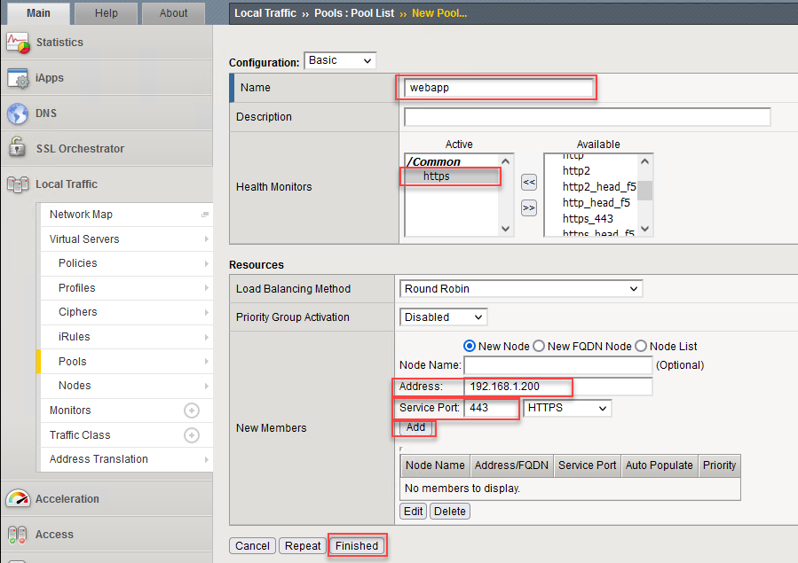
Enter webapp in the Name field.
Select https as the Health Monitor.
Enter 192.168.1.200 in the node Address field.
Enter 443 in the Service Port field.
Click on the Add button.
Click on the Finished button to return to the Pool list.
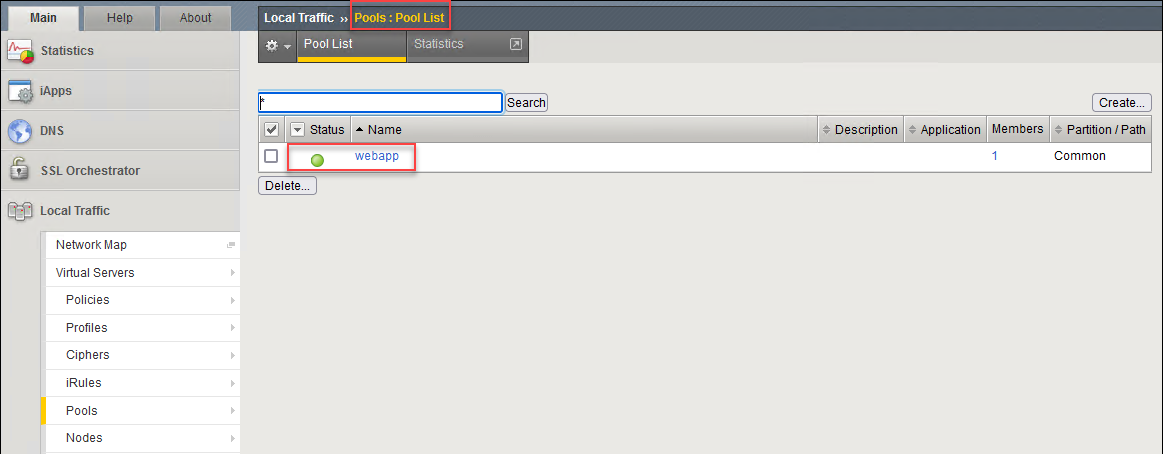
Click on Pools: Pool List to refresh the list. The webapp pool status will change to available (green dot). This means that the Wordpress application server is responding to the HTTPS health checks.
3.2.3. Create SSL Orchestrator Topology
In the left panel menu, click on SSL Orchestrator > Configuration. This will initialize the SSL Orchestrator Guided Configuration UI.
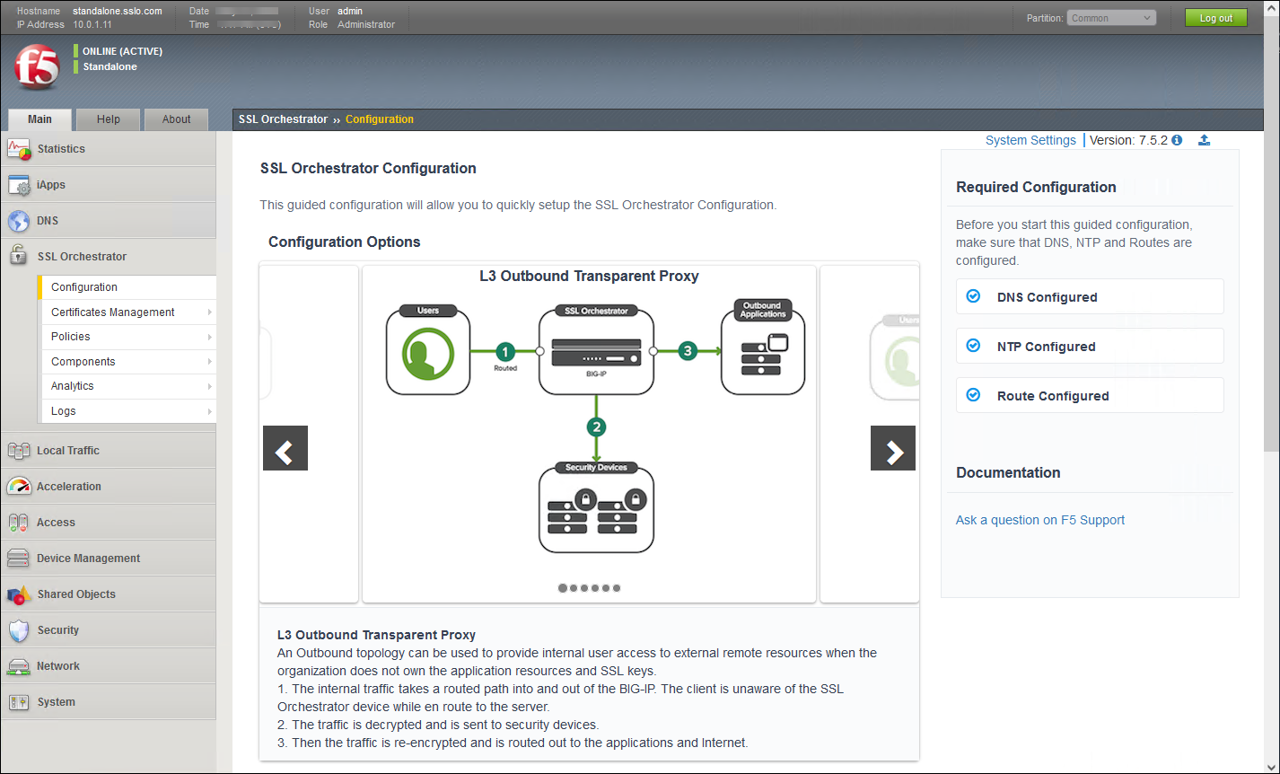
Scroll to the bottom of the Configuration introduction page and click on the Next button to start creating a new Topology.
Enter l3inboundapp as the topology name.
Select the L3 Inbound topology type.
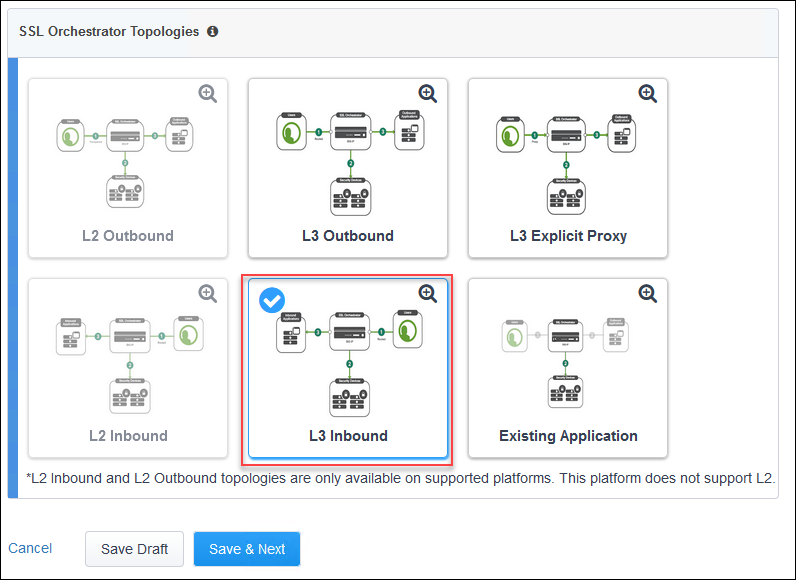
Click on the Save & Next button to continue.
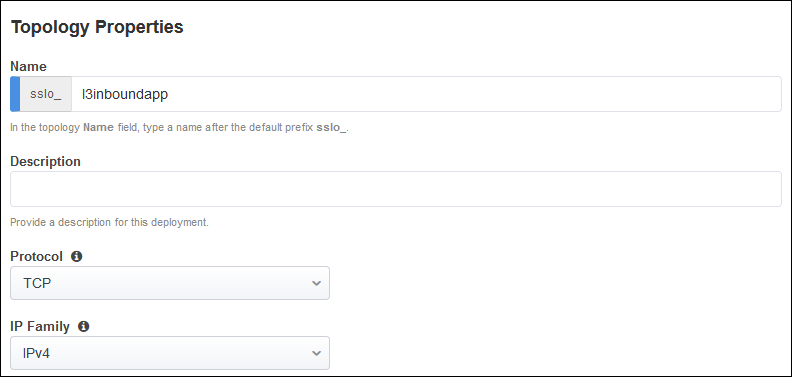
Scroll down to the bottom of the page and click on the Save & Next button.

3.2.4. Create SSL Configuration
On the SSL Configurations page, leave the default Client-side SSL and Server-side SSL settings.
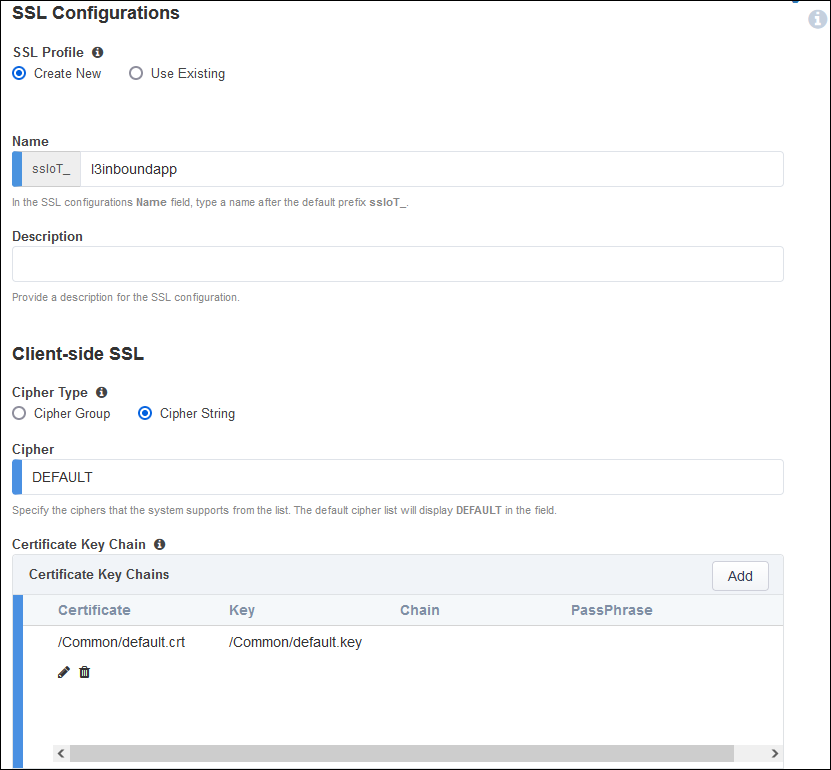
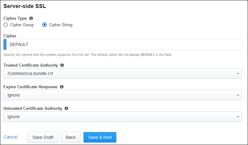
Click on the Save & Next button to continue.
3.2.5. Create Services
Create the first inspection service:
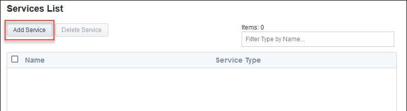
Click on the Add Service button.
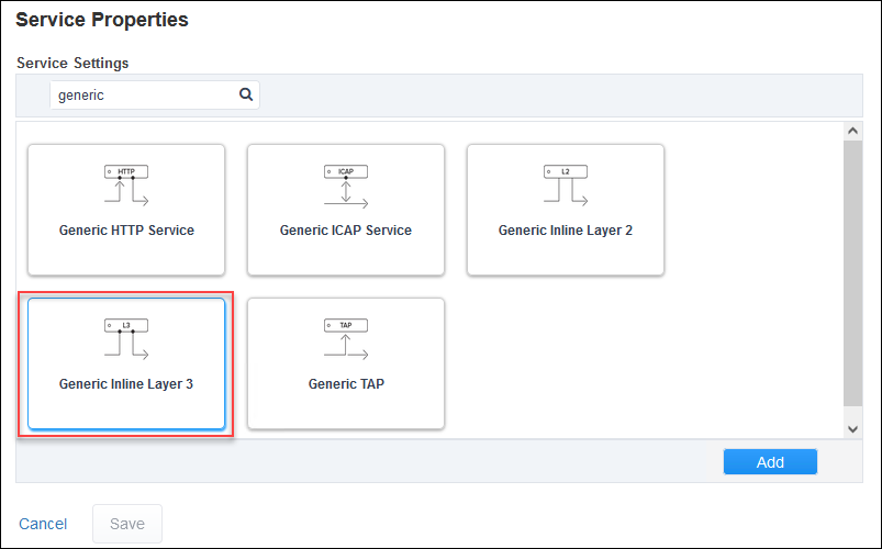
Enter
genericin the search box.Select Generic Inline Layer 3 from the service catalog and click on the Add button.
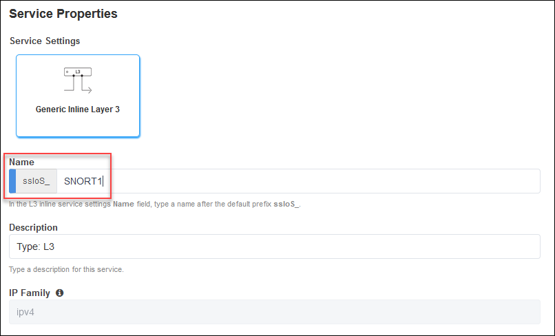
Enter
SNORT1as the name for the service.
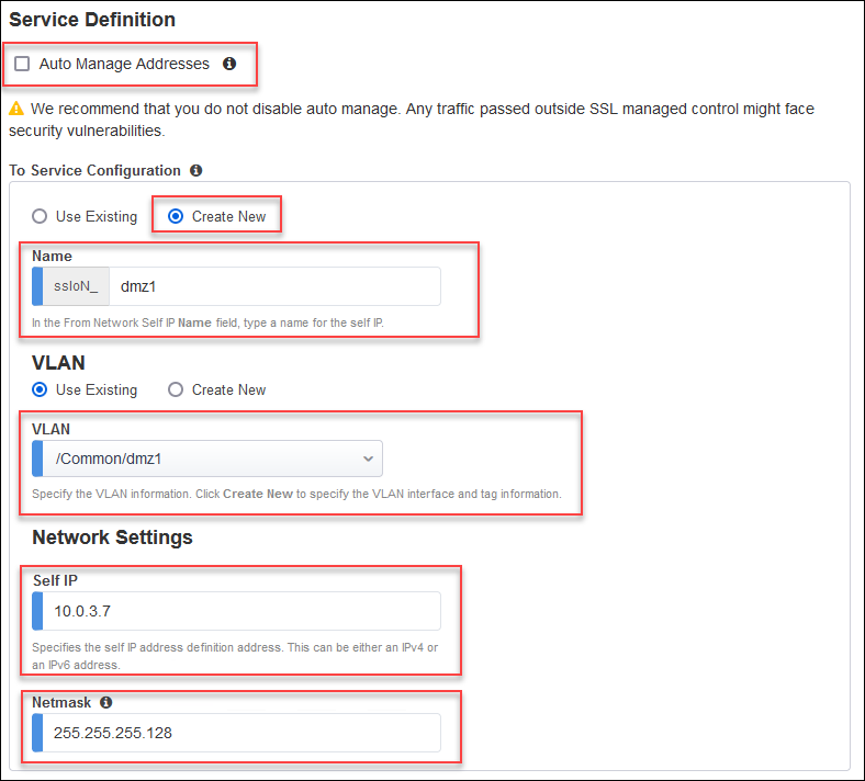
De-select the Auto Manage Addresses checkbox.
In the To Service section, select the Create New radio button.
Enter
dmz1in the self IP name field.Select the Use Existing VLAN radio button (if not already selected).
Select the /Common/dmz1 VLAN.
Enter
10.0.3.7in the Self IP address field.Enter
255.255.255.128in the Netmask field.
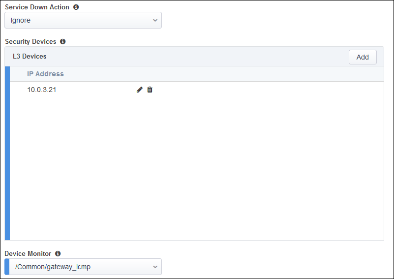
Add an L3 Device with IP address of
10.0.3.21(matches the value of the inspection_service_ip_1 Terraform output)
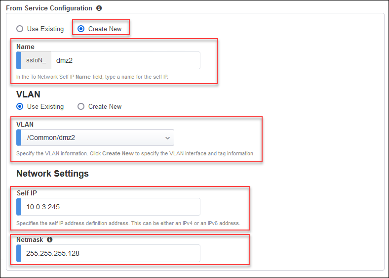
In the From Service section, select the Create New radio button.
Enter
dmz2in the self IP name field.Select the Use Existing VLAN radio button (if not already selected).
Select the /Common/dmz2 VLAN.
Enter
10.0.3.245in the Self IP address field.Enter
255.255.255.128in the Netmask field.
Leave the defaults for the remaining settings.
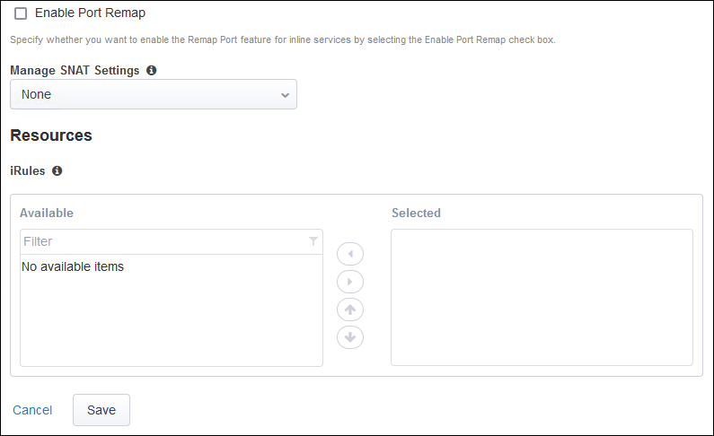
Click on the Save button.
Create the second L3 inspection service:
Click on the Add Service button.
Enter
genericin the search box.Select Generic Inline Layer 3 from the service catalog and click on the Add button.
Enter
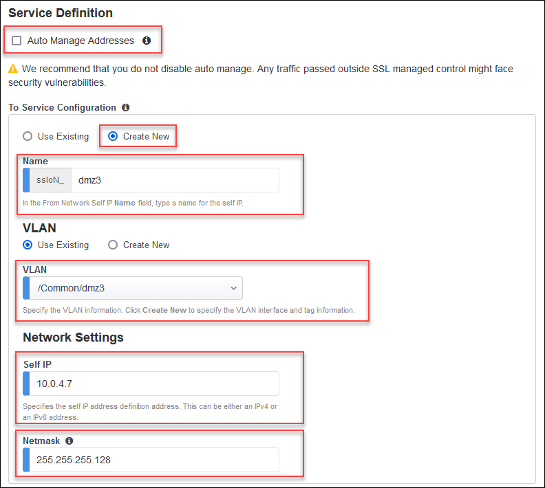
SNORT2as the name for the service.De-select the Auto Manage Addresses checkbox.
In the To Service section, select the Create New radio button.
Enter
dmz3in the self IP name field.Select the Use Existing VLAN radio button (if not already selected).
Select the /Common/dmz3 VLAN.
Enter
10.0.4.7in the Self IP address field.Enter
255.255.255.128in the Netmask field.
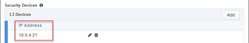
Add an L3 Device with IP address of
10.0.4.21(matches the value of the inspection_service_ip_2 Terraform output)
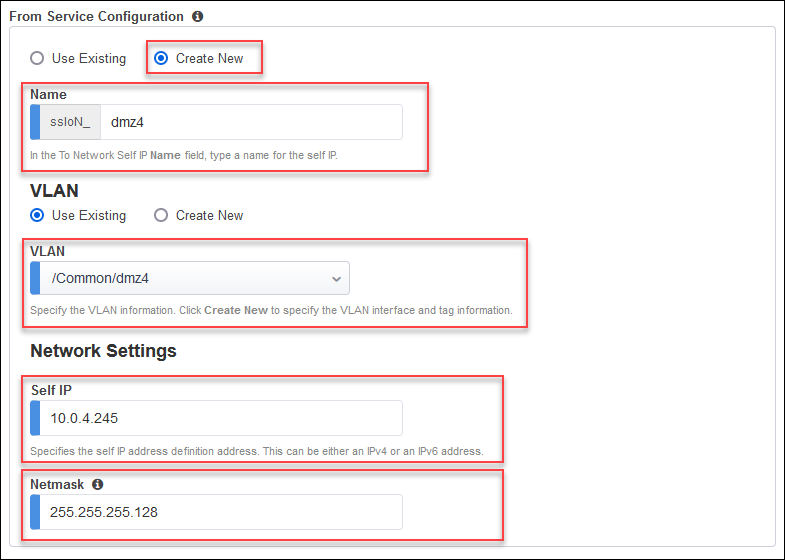
In the From Service section, select the Create New radio button.
Enter
dmz4in the self IP name field.Select the Use Existing VLAN radio button (if not already selected).
Select the /Common/dmz4 VLAN.
Enter
10.0.4.245in the Self IP address field.Enter
255.255.255.128in the Netmask field.
Leave the defaults for the remaining settings.
Click on the Save button.
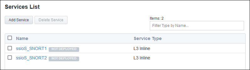
Click on the Save & Next button to continue.
3.2.6. Create Service Chains
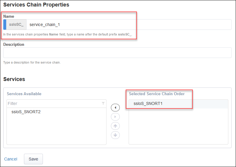
Create first service chain:
Click on the Add button.
Enter
service_chain_1in the name field.Add the SNORT1 service to the service chain.
Click on the Save button.
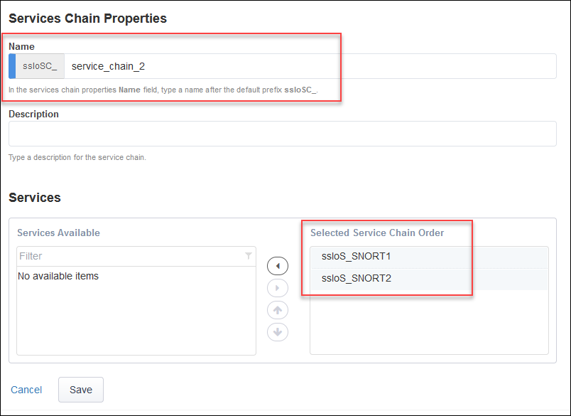
Create second service chain:
Click on the Add button.
Enter
service_chain_2in the name field.Add the SNORT1 and SNORT2 services to the service chain.
Click on the Save button.
Click on the Save & Next button to continue.
3.2.7. Security Policy
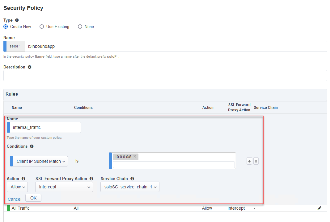
Create a new rule above the default rule with the following options:
Click on the Add button on the right side of the page.
Enter
internal_trafficin the rule name field.Select the Client IP Subnet Match condition and enter
10.0.0.0/8for the subnet value.Set SSL Forward Proxy Action to Intercept.
Set Service Chain to ssloSC_service_chain_1.
Click on the OK button.
Edit the default rule:
Click on the pencil icon for the All Traffic rule.
Set Service Chain to ssloSC_service_chain_2.
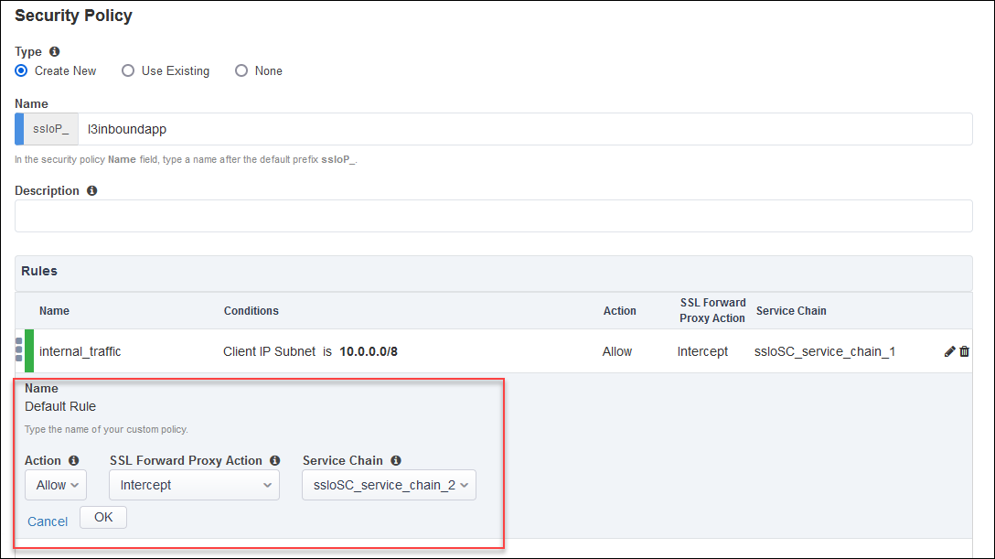
Click on the OK button.
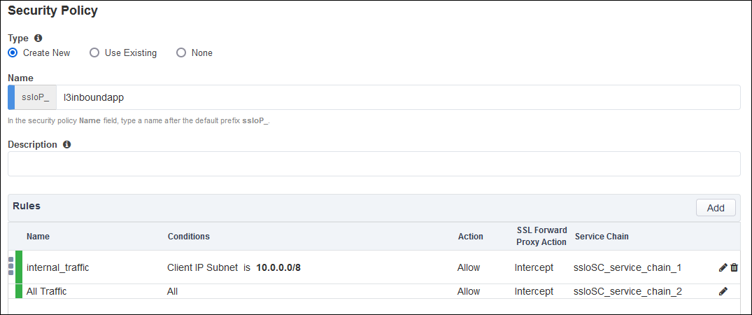
Click on the Save & Next button to continue.
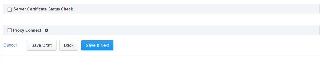
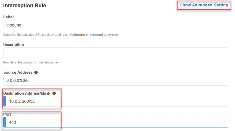
3.2.8. Interception Rule
Click on the Show Advanced Setting link at the top right corner. This is required to reveal the Pool selection option.
Enter 10.0.2.200/32 in the Destination Address/mask field.
Ener 443 in the Port field.
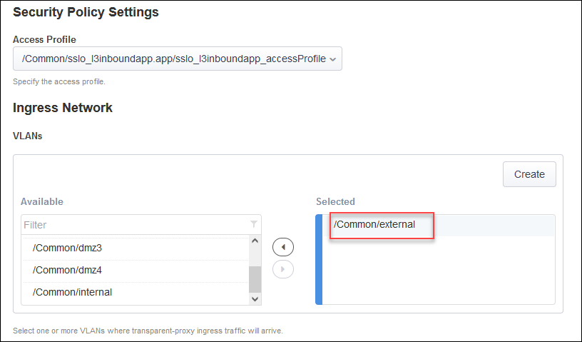
For the Ingress Network, select the /Common/external VLAN.
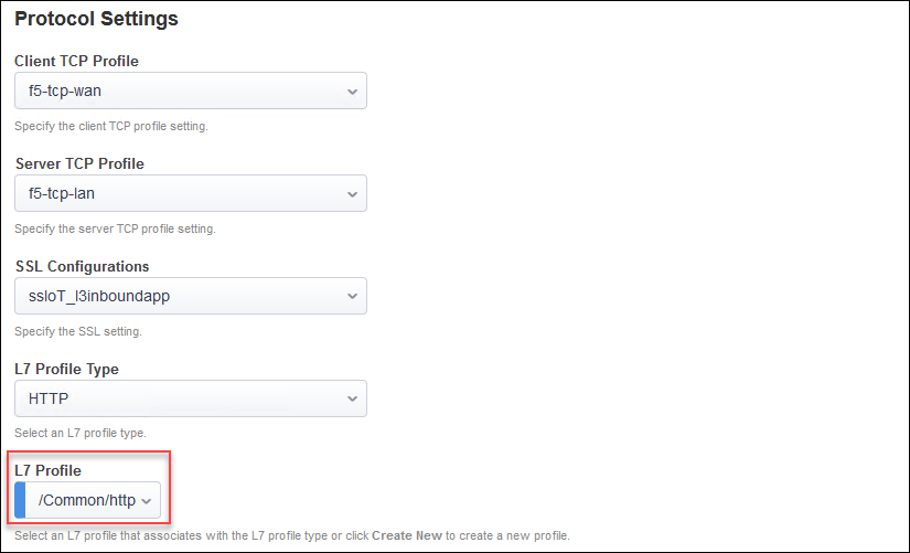
For the L7 Profile, select /Common/http.
Important
If you do not see the Resources section, then you need to return to the top of the page and click on the Show Advanced Setting link before continuing.
In the Resources section, click on the Pool drop-down list and select the webapp pool.
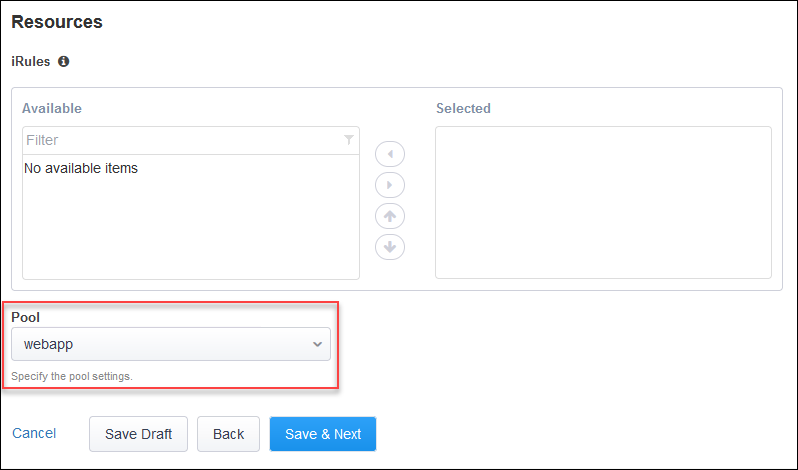
Click on the Save & Next button to continue.
3.2.9. Egress Settings
Enable SNAT Auto Map for traffic egress and use the default route as a gateway.
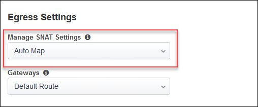
Click on the Save & Next button to continue.
3.2.10. Log Settings
Leave the default log settings.
Click on Save & Next.
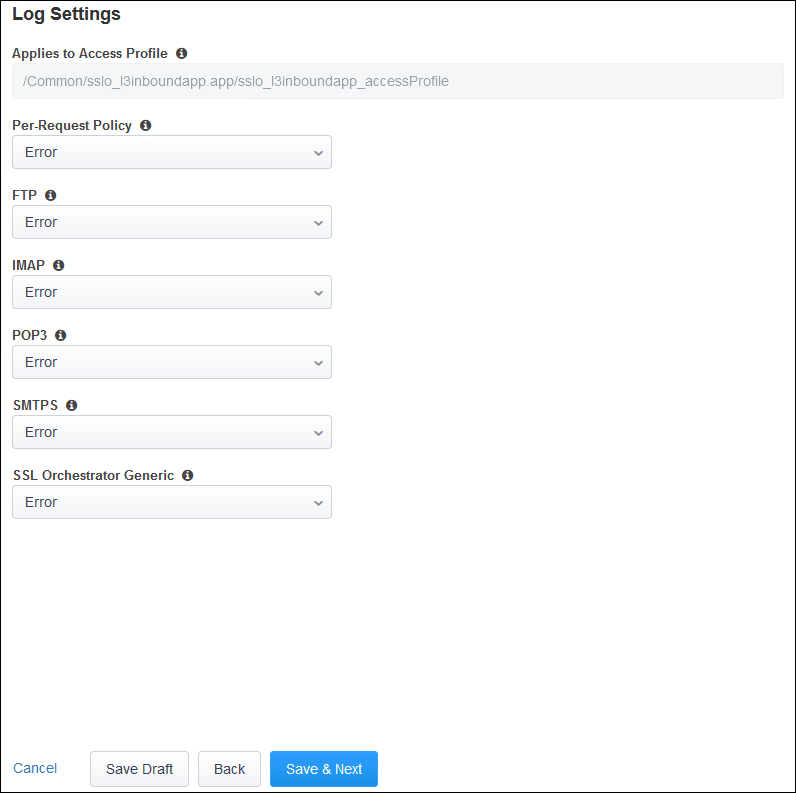
Click on the Save & Next button to continue.
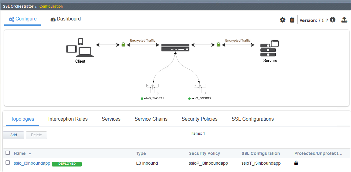
3.2.11. Deploy Topology
Click on the Deploy button to create the new Topology configuration.
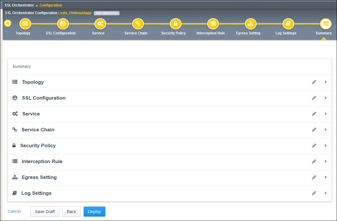
Wait for the deployment to complete.
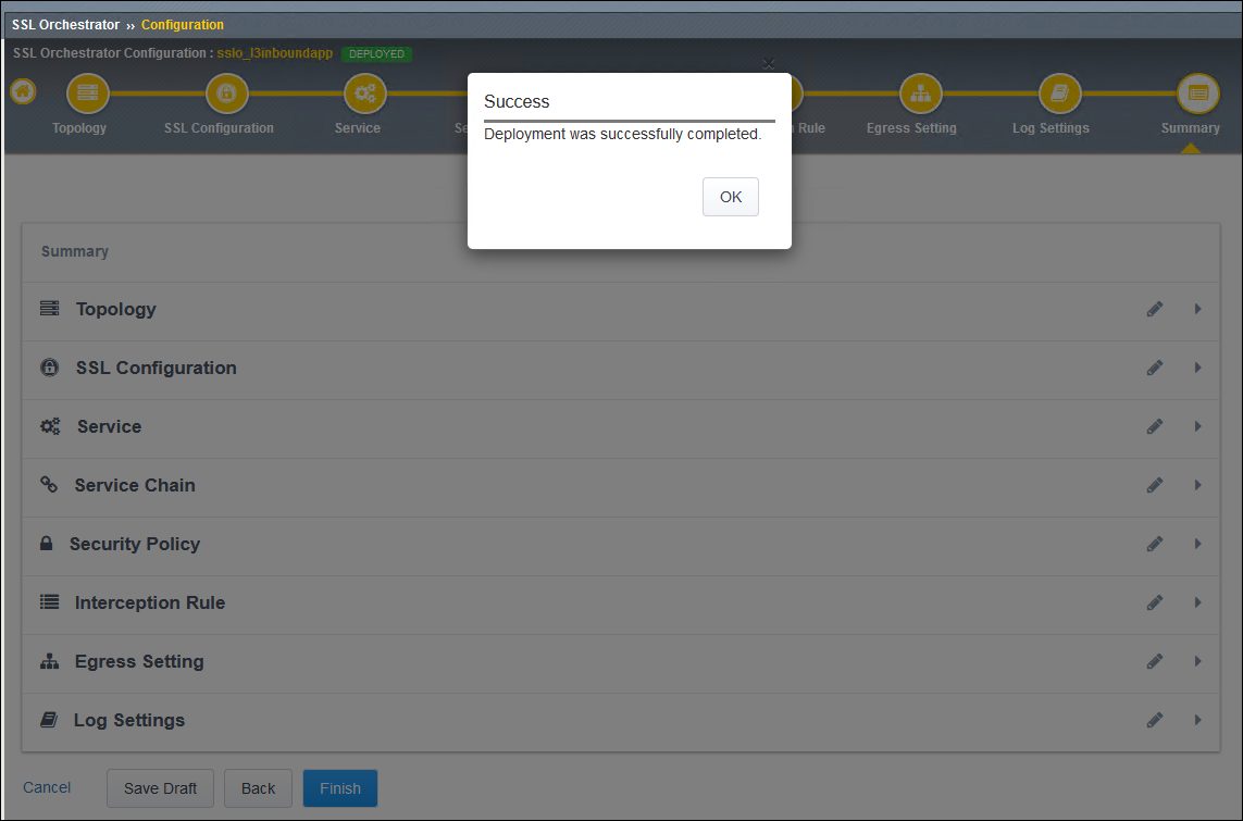
Click on the OK button to continue.